EP1473484A2 - Torsional vibration damper - Google Patents
Torsional vibration damper Download PDFInfo
- Publication number
- EP1473484A2 EP1473484A2 EP04009757A EP04009757A EP1473484A2 EP 1473484 A2 EP1473484 A2 EP 1473484A2 EP 04009757 A EP04009757 A EP 04009757A EP 04009757 A EP04009757 A EP 04009757A EP 1473484 A2 EP1473484 A2 EP 1473484A2
- Authority
- EP
- European Patent Office
- Prior art keywords
- area
- damper
- output
- torsional vibration
- region
- Prior art date
- Legal status (The legal status is an assumption and is not a legal conclusion. Google has not performed a legal analysis and makes no representation as to the accuracy of the status listed.)
- Granted
Links
Images

Classifications
-
- F—MECHANICAL ENGINEERING; LIGHTING; HEATING; WEAPONS; BLASTING
- F16—ENGINEERING ELEMENTS AND UNITS; GENERAL MEASURES FOR PRODUCING AND MAINTAINING EFFECTIVE FUNCTIONING OF MACHINES OR INSTALLATIONS; THERMAL INSULATION IN GENERAL
- F16F—SPRINGS; SHOCK-ABSORBERS; MEANS FOR DAMPING VIBRATION
- F16F15/00—Suppression of vibrations in systems; Means or arrangements for avoiding or reducing out-of-balance forces, e.g. due to motion
- F16F15/10—Suppression of vibrations in rotating systems by making use of members moving with the system
- F16F15/12—Suppression of vibrations in rotating systems by making use of members moving with the system using elastic members or friction-damping members, e.g. between a rotating shaft and a gyratory mass mounted thereon
- F16F15/1207—Suppression of vibrations in rotating systems by making use of members moving with the system using elastic members or friction-damping members, e.g. between a rotating shaft and a gyratory mass mounted thereon characterised by the supporting arrangement of the damper unit
-
- F—MECHANICAL ENGINEERING; LIGHTING; HEATING; WEAPONS; BLASTING
- F16—ENGINEERING ELEMENTS AND UNITS; GENERAL MEASURES FOR PRODUCING AND MAINTAINING EFFECTIVE FUNCTIONING OF MACHINES OR INSTALLATIONS; THERMAL INSULATION IN GENERAL
- F16F—SPRINGS; SHOCK-ABSORBERS; MEANS FOR DAMPING VIBRATION
- F16F15/00—Suppression of vibrations in systems; Means or arrangements for avoiding or reducing out-of-balance forces, e.g. due to motion
- F16F15/10—Suppression of vibrations in rotating systems by making use of members moving with the system
- F16F15/12—Suppression of vibrations in rotating systems by making use of members moving with the system using elastic members or friction-damping members, e.g. between a rotating shaft and a gyratory mass mounted thereon
- F16F15/121—Suppression of vibrations in rotating systems by making use of members moving with the system using elastic members or friction-damping members, e.g. between a rotating shaft and a gyratory mass mounted thereon using springs as elastic members, e.g. metallic springs
- F16F15/123—Wound springs
- F16F15/1238—Wound springs with pre-damper, i.e. additional set of springs between flange of main damper and hub
-
- F—MECHANICAL ENGINEERING; LIGHTING; HEATING; WEAPONS; BLASTING
- F16—ENGINEERING ELEMENTS AND UNITS; GENERAL MEASURES FOR PRODUCING AND MAINTAINING EFFECTIVE FUNCTIONING OF MACHINES OR INSTALLATIONS; THERMAL INSULATION IN GENERAL
- F16F—SPRINGS; SHOCK-ABSORBERS; MEANS FOR DAMPING VIBRATION
- F16F15/00—Suppression of vibrations in systems; Means or arrangements for avoiding or reducing out-of-balance forces, e.g. due to motion
- F16F15/10—Suppression of vibrations in rotating systems by making use of members moving with the system
- F16F15/12—Suppression of vibrations in rotating systems by making use of members moving with the system using elastic members or friction-damping members, e.g. between a rotating shaft and a gyratory mass mounted thereon
- F16F15/129—Suppression of vibrations in rotating systems by making use of members moving with the system using elastic members or friction-damping members, e.g. between a rotating shaft and a gyratory mass mounted thereon characterised by friction-damping means
Abstract
Description
Die vorliegende Erfindung betrifft einen Torsionsschwingungsdämpfer, umfassend einen ersten Dämpferbereich mit einem ersten Eingangsbereich und einem ersten Ausgangsbereich, welcher über eine erste Dämpferelementenanordnung zur Drehmomentübertragung mit dem ersten Eingangsbereich gekoppelt ist, einen zweiten Dämpferbereich mit einem zweiten Eingangsbereich, der mit dem ersten Ausgangsbereich des ersten Dämpferbereichs in Drehmomentübertragungsverbindung steht, und mit einem zweiten Ausgangsbereich, der über eine zweite Dämpferelementenanordnung zur Drehmomentübertragung mit dem zweiten Eingangsbereich gekoppelt ist und mit einem Abtriebselement in Drehmomentübertragungsverbindung steht, wobei eine Drehwinkelbegrenzungsanordnung vorgesehen ist, welche eine Relativdrehung zwischen dem ersten Ausgangsbereich des ersten Dämpferbereichs und dem Abtriebselement in einem vorbestimmten Winkelbereich um eine Drehachse zulässt.The present invention relates to a torsional vibration damper, comprising a first damper area with a first input area and a first output area, which via a first damper element arrangement for torque transmission with the first input area is coupled, a second damper area with a second Input area, which with the first output area of the first damper area is in torque transmission connection, and with a second output area, via a second damper element arrangement coupled to the second input area for torque transmission is and with an output element in torque transmission connection stands, wherein a rotation angle limiting arrangement is provided which is a relative rotation between the first output range of the first damper area and the output element in a predetermined Allows angular range around an axis of rotation.
Ein derartiger in einer Kupplungsscheibe vorgesehener Torsionsschwingungsdämpfer ist aus der DE 39 21 283 A1 bekannt. Dieser zweistufig aufgebaute Torsionsschwingungsdämpfer weist als Lastdämpferbereich einen ersten Dämpferbereich auf, der mit seinem ersten Eingangsbereich die Reibbeläge trägt und mit seinem ersten Ausgangsbereich bezüglich einer als Abtriebselement wirksamen Nabe in einem vorbestimmten Drehwinkelbereich drehbar ist. Hierzu sind am Außenumfang der Nabe einerseits und am Innenumfang des als Blechstanzteil scheibenartig ausgebildeten ersten Ausgangsbereichs jeweils Verzahnungen vorgesehen, die mit einem vorbestimmten Drehwinkel bezüglich einander verdrehbar sind und somit eine Drehwinkelbegrenzungsanordnung definieren. Der als Vordämpfer wirksame zweite Dämpferbereich weist einen Eingangsbereich auf, der mit dem scheibenartig ausgebildeten Ausgangsbereich des Hauptdämpfers drehfest gekoppelt ist. Der ebenfalls scheibenartig ausgebildete zweite Ausgangsbereich des Vordämpfers ist mit der Nabe, also dem Abtriebselement, beispielsweise im Bereich der dort vorgesehenen Verzahnung drehfest gekoppelt.Such a torsional vibration damper provided in a clutch disc is known from DE 39 21 283 A1. This two-stage constructed torsional vibration damper points as a load damper area a first damper area with the first input area carries the friction linings and with respect to its first exit area a hub acting as an output element in a predetermined Angle range is rotatable. For this are on the outer circumference of the hub on the one hand and on the inner circumference of the disc-shaped sheet metal stamping first output area provided gears each are rotatable with respect to each other with a predetermined angle of rotation and thus define a rotation angle limitation arrangement. The one as a pre-damper effective second damper area has an entrance area, the with the disc-shaped output area of the main damper is rotatably coupled. The also disc-shaped second output area of the pre-damper is with the hub, ie the Output element, for example in the area of the toothing provided there non-rotatably coupled.
Ein Problem bei einem derartigen Torsionsschwingungsdämpfer besteht darin, dass im Wirkungsbereich des Hauptdämpfers das zu übertragende Drehmoment über die beiden angesprochenen Verzahnungen an dem Scheibenelement bzw. der Nabe zu übertragen ist. Allein der Aufbau des Scheibenelements mit seiner beschränkten axialen Dicke legt hier eine elementare Beschränkung auf, da aufgrund der beschränkten axialen Dicke hier auch eine entsprechende Beschränkung in der Verzahnungsdicke vorhanden ist, die dazu führt, dass durch eine entsprechende Mindestanzahl an Zähnen eine gewisse Kompensation vorgesehen werden muss. Diese vergleichsweise große Anzahl an Zähnen bedingt jedoch, dass der Drehwinkelbereich, in dem der Ausgangsbereich des Hauptdämpfers bezüglich der Nabe drehbar ist, beschränkt ist, was wieder den Wirkungsbereich des Vordämpfers beschränkt. Der Übergang zu dickeren scheibenartigen Ausgangsbereichen des Hauptdämpfers ist insofern schwierig, als diese scheibenartigen Bauteile im Allgemeinen stanztechnisch und aus Blechmaterial hergestellt werden und die auf diese Art und Weise durchgeführte Herstellung nur bis zu einer bestimmten Dicke des Blechmaterials mit vertretbarem Aufwand durchführbar ist.There is a problem with such a torsional vibration damper in that the area to be transmitted is in the effective range of the main damper Torque on the two gears mentioned on the Disc element or the hub is to be transferred. The construction of the Disc element with its limited axial thickness is one here elementary restriction on because of the limited axial thickness here also a corresponding limitation in the tooth thickness is present, which leads to a corresponding minimum number some compensation must be provided on teeth. However, this comparatively large number of teeth means that the Angular range in which the output range of the main damper is related the hub is rotatable, which is again the scope of the pre-damper limited. The transition to thicker disc-like ones Output areas of the main damper is difficult in that these disc-like components are generally stamped and made Sheet material are produced and carried out in this way Production only up to a certain thickness of the sheet material is feasible with reasonable effort.
Es ist das Ziel der vorliegenden Erfindung, einen gattungsgemäßen Torsionsschwingungsdämpfer derart weiterzubilden, dass bei vergrößertem Wirkungsbereich des zweiten Dämpferbereichs größere Drehmomente übertragbar sind.It is the aim of the present invention, a generic torsional vibration damper to develop in such a way that when enlarged Area of effect of the second damper area larger torques are transferable.
Erfindungsgemäß wird diese Aufgabe gelöst durch einen Torsionsschwingungsdämpfer, umfassend einen ersten Dämpferbereich mit einem ersten Eingangsbereich und einem ersten Ausgangsbereich, welcher über eine erste Dämpferelementenanordnung zur Drehmomentübertragung mit dem ersten Eingangsbereich gekoppelt ist, einen zweiten Dämpferbereich mit einem zweiten Eingangsbereich, der mit dem ersten Ausgangsbereich des ersten Dämpferbereichs in Drehmomentübertragungsverbindung steht, und mit einem zweiten Ausgangsbereich, der über eine zweite Dämpferelementenanordnung zur Drehmomentübertragung mit dem zweiten Eingangsbereich gekoppelt ist und mit einem Abtriebselement in Drehmomentübertragungsverbindung steht, wobei eine Drehwinkelbegrenzungsanordnung vorgesehen ist, welche eine Relativdrehung zwischen dem ersten Ausgangsbereich des ersten Dämpferbereichs und dem Abtriebselement in einem vorbestimmten Winkelbereich um eine Drehachse zulässt.According to the invention, this object is achieved by a torsional vibration damper, comprising a first damper area with a first input area and a first output area, which via a first damper element arrangement for torque transmission with is coupled to the first input area, a second damper area with a second input area, that with the first output area the first damper area is in a torque transmission connection, and with a second output area, which via a second damper element arrangement for torque transmission with the second input area is coupled and with an output element in torque transmission connection stands, with a rotation angle limiting arrangement is provided which is a relative rotation between the first Output area of the first damper area and the output element in a predetermined angular range around an axis of rotation.
Dabei ist dann weiter vorgesehen, dass die Drehwinkelbegrenzungsanordnung ein Zwischenelement zwischen dem ersten Ausgangsbereich des ersten Dämpferbereichs und dem Abtriebselement umfasst, welches Zwischenelement mit dem ersten Ausgangsbereich im Wesentlichen drehfest verbunden ist und bezüglich des Abtriebselements in dem vorbestimmten Drehwinkelbereich verdrehbar ist.It is then further provided that the rotation angle limitation arrangement an intermediate element between the first output region of the comprises first damper region and the output element, which intermediate element with the first output area essentially non-rotatable is connected and with respect to the output element in the predetermined Angle range is rotatable.
Bei dem erfindungsgemäßen Torsionsschwingungsdämpfer ist also ein direkter und das übertragbare Drehmoment begrenzender Kontakt zwischen dem ersten Ausgangsbereich und dem Abtriebselement vermieden. Vielmehr ist dieser Kontakt in den Wechselwirkungsbereich zwischen dem Abtriebselement und dem Zwischenelement verlagert. Somit lässt sich einerseits die Kopplung zwischen dem ersten Ausgangsbereich und dem Zwischenelement und andererseits die Kopplung zwischen dem Zwischenelement und dem Abtriebselement optimieren, so dass größere Drehmomente übertragen werden können und überdies der vorbestimmte Drehwinkelbereich im Vergleich zum Stand der Technik deutlich vergrößert werden kann. Dies liegt vor allem daran, dass das Zwischenelement, das in anderer Art und Weise hergestellt werden kann, als der Ausgangsbereich, den vorangehend geschilderten fertigungstechnischen Beschränkungen nicht unterliegt und somit beispielsweise mit deutlich größerer axialer Erstreckung bereitgestellt werden kann, als dies im Falle des ersten Ausgangsbereichs bei vertretbarem Aufwand möglich ist. Somit kann insbesondere die axiale Wechselwirkungslänge der Drehwinkelbegrenzungsanordnung, die nunmehr zwischen dem Abtriebselement und dem Zwischenelement wirksam ist, vergrößert werden, wobei gleichzeitig aber auch der hier zugelassene Freiwinkel vergrößert werden kann. Dies hat zur Folge, dass der zweite Dämpferbereich in einem deutlich größeren Winkelbereich, nämlich dem vergrößerten vorbestimmten Drehwinkelbereich, wirksam sein kann.In the case of the torsional vibration damper according to the invention, there is therefore a direct contact between the torque limitable the first output area and the output element avoided. Much more is this contact in the interaction area between the Output element and the intermediate element relocated. So you can on the one hand the coupling between the first output area and the Intermediate element and on the other hand the coupling between the intermediate element and optimize the output element so that larger torques can be transmitted and also the predetermined range of rotation angle can be significantly enlarged compared to the prior art can. This is mainly because the intermediate element that is in other Way can be manufactured as the exit area above-mentioned manufacturing restrictions is subject and therefore, for example, with a significantly greater axial extent can be provided than in the case of the first exit area is possible with reasonable effort. Thus, in particular the axial interaction length of the rotation angle limiting arrangement, now between the output element and the intermediate element effective, be enlarged, but at the same time also clearance angle allowed here can be enlarged. As a consequence, that the second damper area in a much larger angular area, namely the enlarged predetermined angle of rotation range, be effective can.
Bei einer besonders vorteilhaften Ausgestaltungsform kann vorgesehen sein, dass an einem Innenumfangsbereich des Zwischenelements eine erste Verzahnungsformation vorgesehen ist, die mit einer ersten Gegen-Verzahnungsformation an einem Außenumfangsbereich des Abtriebselements mit dem vorbestimmten Drehwinkelbereich entsprechendem Drehbewegungsspiel in Kämmeingriff steht.In a particularly advantageous embodiment, it can be provided be that a first on an inner peripheral region of the intermediate element Gear formation is provided with a first counter-tooth formation on an outer peripheral region of the output element with the predetermined rotational angle range corresponding rotation movement is in mesh.
Um eine stabile Kopplung zwischen dem ersten Ausgangsbereich und dem Zwischenelement erlangen zu können, wird weiter vorgeschlagen, dass an einem Außenumfangsbereich des Zwischenelements eine zweite Verzahnungsformation vorgesehen ist, welche mit einer zweiten Gegen-Verzahnungsformation am ersten Ausgangsbereich des ersten Dämpferbereichs im Wesentlichen ohne Drehbewegungsspiel in Kämmeingriff steht. Hier ist von Bedeutung, dass bei diesem Kämmeingriff nicht mehr auf das Bereitstellen eines bestimmten Freiwinkels geachtet werden muss, so dass auch bei vergleichsweise dünnem ersten Ausgangsbereich durch entsprechende Umfangserstreckung der daran gebildeten zweiten Gegen-Verzahnungsformation bzw. der Zähne derselben eine ausreichende Stabilität auch zur Übertragung größerer Drehmomente erlangt werden kann. To ensure a stable coupling between the first output area and the To be able to obtain intermediate element, it is further proposed that an outer peripheral region of the intermediate element, a second tooth formation is provided, which with a second counter-tooth formation at the first output area of the first damper area in It meshes substantially without any play in rotation. Here is from Meaning that with this combing intervention no longer on the provision a certain clearance angle must be observed, so that also at comparatively thin first output area by appropriate Extent of extent of the second counter-tooth formation formed on it or the teeth of the same also sufficient stability Transmission of higher torques can be achieved.
Um einen einfachen, gleichwohl jedoch stabilen Aufbau erlangen zu können, wird vorgeschlagen, dass das Zwischenelement ringartig ausgebildet ist.In order to achieve a simple but stable construction, it is proposed that the intermediate element be ring-shaped is.
Wie bereits vorangehend angesprochen, ist es ein elementarer Vorteil des erfindungsgemäßen Torsionsschwingungsdämpfers, dass das Zwischenelement nicht fertigungstechnischen Beschränkungen des ersten Ausgangsbereichs unterliegt, insbesondere wenn dieser als ein scheibenartiges Blechteil stanztechnisch herzustellen ist. Es wird daher weiter vorgeschlagen, dass der erste Ausgangsbereich ein Scheibenelement umfasst und dass eine Erstreckungslänge der ersten Verzahnungsformation in Richtung der Drehachse größer ist, als eine axiale Dicke des Scheibenelements. Beispielsweise kann vorgesehen sein, dass die erste Verzahnungsformation und die erste Gegen-Verzahnungsformation im Wesentlichen die gleiche Axialerstreckungslänge aufweisen. Um eine definierte Positionierung des Zwischenelements bezüglich des ersten Ausgangsbereichs und somit insbesondere auch bezüglich des Abtriebselements vorgeben zu können, wird vorgeschlagen, dass an dem Zwischenelement wenigstens ein Axialanlagebereich zur axialen Abstützung an dem ersten Ausgangsbereich des ersten Dämpferbereichs vorgesehen ist.As mentioned earlier, it is a fundamental advantage of the Torsional vibration damper according to the invention that the intermediate element non-manufacturing restrictions of the first output area subject, especially if this as a disc-like Sheet metal part is to be stamped. It is therefore further proposed that the first exit region comprises a disk element and that an extension length of the first tooth formation in the direction the axis of rotation is greater than an axial thickness of the disc element. For example, it can be provided that the first tooth formation and the first counter-tooth formation is substantially the same Have axial extension length. For a defined positioning of the Intermediate element with respect to the first output area and thus to be able to specify in particular also with regard to the output element, it is proposed that at least one axial contact area on the intermediate element for axial support at the first exit area of the first damper area is provided.
Gemäß einem weiteren Aspekt betrifft die vorliegende Erfindung eine Kupplungsscheibe, umfassend einen erfindungsgemäßen Torsionsschwingungsdämpfer, wobei mit dem ersten Eingangsbereich des ersten Dämpferbereichs eine Reibflächenanordnung zur Drehmomentübertragung verbunden ist und wobei das Abtriebselement mit einer Abtriebswelle, beispielsweise Getriebeeingangswelle, zur gemeinsamen Drehung um die Drehachse verbindbar ist.According to a further aspect, the present invention relates to a Clutch disc, comprising a torsional vibration damper according to the invention, with the first input area of the first damper area a friction surface arrangement for torque transmission connected is and wherein the output element with an output shaft, for example Gearbox input shaft, for common rotation around the axis of rotation is connectable.
Die vorliegende Erfindung wird nachfolgend mit Bezug auf die beiliegenden Zeichnungen detailliert beschrieben. Es zeigt:
- Fig. 1
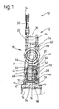
- eine Teil-Längsschnittansicht eines in einer Kupplungsscheibe vorgesehenen erfindungsgemäßen Torsionsschwingungsdämpfers;
- Fig. 2
- eine perspektivische Ansicht eines bei dem Torsionsschwingungsdämpfer der Fig. 1 eingesetzten ringartigen Zwischenelements;
- Fig. 3
- das Zwischenelement der Fig. 2 in Axialansicht;
- Fig. 4
- das Zwischenelement der Fig. 2 in Längsschnittansicht.
- Fig. 1
- a partial longitudinal sectional view of a torsional vibration damper according to the invention provided in a clutch disc;
- Fig. 2
- a perspective view of an annular element used in the torsional vibration damper of Figure 1;
- Fig. 3
- the intermediate element of Figure 2 in axial view.
- Fig. 4
- the intermediate element of FIG. 2 in longitudinal sectional view.
In Fig. 1 ist eine Kupplungsscheibe allgemein mit 10 bezeichnet. Diese
Kupplungsscheibe 10 umfasst einen nachfolgend noch detaillierter beschriebenen
Torsionsschwingungsdämpfer 12, durch welchen die Reibbeläge
14 dieser Kupplungsscheibe 10 über eine Abtriebsnabe 16 an eine
nicht dargestellte Getriebeeingangswelle o.dgl. zur gemeinsamen Drehung
mit dieser um eine Drehachse A angebunden werden können.In Fig. 1, a clutch disc is generally designated 10. This
Clutch disc 10 includes one described in more detail below
Der Torsionsschwingungsdämpfer 12 umfasst zwei allgemein mit 18 und
20 bezeichnete Dämpferbereiche. Der erste Dämpferbereich 18, welcher
auch allgemein als Hauptdämpfer bezeichnet werden kann, umfasst als
Eingangsbereich 22 zwei in axialem Abstand zueinander angeordnete und
miteinander durch Nietelemente 24 o.dgl. fest verbundene, beispielsweise
aus Blechmaterial hergestellte Deckscheibenelemente 26, 28. Mit dem
Deckscheibenelement 26 sind über eine Belagfederung 30 o.dgl. die Reibbeläge
14 fest verbunden. Ein Ausgangsbereich 32 dieses ersten Dämpferbereichs
18 umfasst ein beispielsweise ebenfalls aus Blechmaterial stanztechnisch
hergestelltes Zentralscheibenelement 34. Radial außen greift
dieses mit Armabschnitten 36 zwischen die Nietbolzen 24 mit Drehbewegungsspiel
ein, so dass ein maximaler Relativdrehwinkel für den Eingangsbereich
18 und den Ausgangsbereich 32 vorgegeben ist. Über eine
Mehrzahl von Dämpferfedern 38, die in an sich bekannter Art und Weise in
jeweiligen Federfenstern der Deckscheibenelemente 26, 28 bzw. des
Zentralscheibenelements 34 angeordnet sind und sich daran umfangsmäßig
abstützen, ist der Eingangsbereich 18 mit dem Ausgangsbereich 32 zur
Drehmomentübertragung gekoppelt, so dass bedingt durch die Komprimierbarkeit
der Dämpferfedern 38 und die zugelassene Relativdrehbarkeit des
Eingangsbereichs 18 bezüglich des Ausgangsbereichs 32 bei Auftreten von
Drehschwingungen eine Dämpfungsfunktion erfüllt werden kann.The
Der zweite Dämpferbereich 20 umfasst als Eingangsbereich 40 zwei miteinander
und auch mit dem Zentralscheibenelement 34 des ersten Dämpferbereichs
18 drehfest verbundene und beispielsweise aus Blechmaterial gefertigte
Deckscheibenelemente 42, 44. Das Deckscheibenelement 44 kann
dabei mehrere axial abgebogene Lappenbereiche 46 aufweisen, die in
entsprechende Umfangsausnehmungen des Deckscheibenelements 42 und
Öffnungen im Zentralscheibenelement 34 eingreifen und somit die im
Wesentlichen drehfeste Kopplung zwischen dem Eingangsbereich 40 des
zweiten Dämpferbereichs 20 und dem Ausgangsbereich 32 des ersten
Dämpferbereichs 18 herstellen.The
Der Ausgangsbereich 48 des zweiten Dämpferbereichs 20 umfasst ebenfalls
ein Zentralscheibenelement 50, das zwischen den beiden Deckscheibenelementen
42, 44 angeordnet ist und mit diesen über eine Mehrzahl von
Dämpferfedern 52 zur Drehmomentübertragung gekoppelt ist. Auch diese
Dämpferfedern 52 stützen sich an jeweiligen Federfenstern in den Deckscheibenelementen
42, 44 bzw. dem Zentzralscheibenelement 50 ab und
ermöglichen somit unter deren Umfangskompression eine Relativdrehung
zwischen dem Eingangsbereich 40 und dem Ausgangsbereich 48 des
zweiten Dämpferbereichs 20.The
Der Ausgangsbereich 48 bzw. das Zentralscheibenelement 50 des zweiten
Dämpferbereichs 20 ist mit der Nabe 16 im Bereich einer am Außenumfang
derselben vorgesehenen Verzahnung 54 drehfest gekoppelt. Hierzu weist
auch das Zentralscheibenelement 50 an seinem Innenumfangsbereich eine
entsprechende Verzahnung 56 auf, die mit der Verzahnung 54 am Nabenelement
16 ohne Umfangsbewegungsspiel in Kämmeingriff steht. An einem
stufenartigen Erweiterungsbereich 58 der Verzahnung 54 kann das Zentralscheibenelement
50 in einer Richtung axial abgestützt sein. Hierzu ist ein
unter Federvorspannung stehendes Reibelement 60 bezüglich des Deckscheibenelements
28 des ersten Eingangsbereichs 22 einerseits und des
Zentralscheibenelements 50 andererseits abgestützt. Die dadurch erzeugte
Reaktionskraft wird über ein zwischen dem anderen Deckscheibenelement
26 des Eingangsbereichs 22 und der Verzahnung 54 der Nabe 16 wirkendes
Lagerelement 62 aufgenommen. Somit ist neben einer definierten
Positionierung des Zentralscheibenelements 50 bezüglich der Nabe 1 6 auch
eine definierte Positionierung des Eingangsbereichs 22 des ersten Dämpferbereichs
18 bezüglich des Nabenelements 16 vorgegeben.The
Ferner erkennt man ein Reibelement 64, das unter Federvorspannung
bezüglich des Deckscheibenelements 26 einerseits und des Zentralscheibenelements
34 andererseits abgestützt ist. Auf diese Art und Weise wird
das Zentralscheibenelement 24 gegen das Deckscheibenelement 42 des
Eingangsbereichs 40 und damit das Deckscheibenelement 44 dieses Eingangsbereichs
40 unter Zwischenlagerung eines weiteren Reib- oder Abstützelements
66 gegen das Deckscheibenelement 28 gepresst. Neben der
auf diese Art und Weise auch eingeführten Reibwirkung ist auch eine
definierte Positionierung des Zentralscheibenelements 34 in axialer Richtung
bezüglich der beiden Deckscheibenelemente 26, 28 und somit auch
bezüglich der Nabe 16 vorgegeben.Furthermore, a
Zwischen dem radial inneren Bereich des Zentralscheibenelements 34 des
Ausgangsbereichs 32 und der Nabe 16 ist ein ringartig ausgestaltetes
Zwischenelement 70 vorgesehen. Dieses ist, wie im Folgenden noch dargelegt,
mit dem Zentralscheibenelement 34 drehfest gekoppelt, und ist mit
der Nabe 16 derart gekoppelt, dass dieses Zwischenelement 70 in einem
vorbestimmten Drehwinkelbereich bezüglich der Nabe 16 verdrehbar ist.
Auf diese Art und Weise ist in Entsprechung zu diesem vorbestimmten
Drehwinkelbereich auch der Wirkungswinkel für den zweiten Dämpferbereich
20 vorgegeben. Da nämlich das Zentralscheibenelement 50 desselben
drehfest mit der Nabe 16 verbunden ist und darüber hinaus die Deckscheibenelemnte
42, 44 desselben mit dem Zentralscheibenelement 34 des
ersten Dämpferbereichs 18 drehfest verbunden sind, kann eine Relativdrehung
zwischen dem Eingangsbereich 40 und dem Ausgangsbereich 48
des zweiten Dämpferbereichs 20 dann nur in demjenigen Winkelbereich
stattfinden, in welchem das Zentralscheibenelement 34 und somit das
Zwischenelement 70 bezüglich der Nabe 16 verdrehbar sind. Hier ist also
eine Drehwinkelbegrenzungsanordnung vorgesehen, welche den Winkelwirkungsbereich
für den zweiten Dämpferbereich 40 vorgibt und diesen bei
Erreichen des maximalen Wirkwinkels dann gegen weitere Kompression
schützt und somit auch teilweise überbrückt.Between the radially inner region of the
Der Aufbau des Zwischenelements 70 wird nachfolgend mit Bezug auf die
Fig. 2 bis 4 detailliert beschrieben.The structure of the
In diesen Figuren erkennt man das Zwischenelement 70, das einen ringartigen,
im Wesentlichen zylindrischen Körperbereich 72 aufweist. An einer
Innenumfangsseite dieses Körperbereichs 72 ist eine allgemein mit 74
bezeichnete Verzahnung vorgesehen, die im dargestellten Beispiel sechs
Zähne aufweist, die mit der Verzahnung 54 der Nabe 16 so in Kämmeingriff
stehen, dass dieses Zwischenelement 70 in einem vorbestimmten
Drehwinkelbereich bezüglich der Nabe 16 um die Drehachse A drehbar ist.
An der Außenumfangsseite des Körperbereichs 72 ist eine weitere Verzahnung
76 vorgesehen. Mit dieser Verzahnung 76 steht eine am Innenumfangsbereich
des Zentralscheibenelements 34 vorgesehene Verzahnung
78 in Kämmeingriff. Die beiden Verzahnungen 76, 78 sind so aufeinander
abgestimmt, dass zwischen dem Zwischenelement 70 und dem Zentralscheibenelement
34 kein Drehbewegungsspiel vorhanden ist. Vielmehr ist
vorzugsweise vorgesehen, dass im Bereich dieser Verzahnungen 76, 78 ein
fester, beispielsweise durch Verpressen bzw. Verstemmen herstellbarer
Verbund zwischen dem Zwischenelement 70 und dem Zentralscheibenelement
34 erzeugt wird. Auf diese Art und Weise wird eine feste und
definierte Halterung des Zwischenelements 70 am Zentralscheibenelement
34 erlangt. Hierzu ist zusätzlich an einem axialen Endbereich ein vorzugsweise
ringartig umlaufender Bund 80 vorgesehen, der bei vollständig auf
das Zentralscheibenelement 34 aufgeschobenem Zwischenelement 70 am
Zentralscheibenelement 34 anliegt und somit eine definierte Axialpositionierung
des Zwischenelements 70 bezüglich des Zentralscheibenelements 34
und somit auch bezüglich allen anderen Komponenten des Torsionsschwingungsdämpfers
12 vorgibt.In these figures, the
Man erkennt aus der vorangehenden Beschreibung, dass somit die Drehwinkelbegrenzungsfunktion
für den zweiten Dämpferbereich 20 im Bereich
der Verzahnungen 74, 54 realisiert ist. Dabei ist jedoch nunmehr selbst bei
vergleichsweise geringer Anzahl an Zähnen der Verzahnung 74 und somit
größerem möglichen Drehbewegungsspiel des Zwischenelements 70 bezüglich
der Nabe 16 gleichwohl die Übertragung hoher Drehmomente
möglich, da die Zähne der Verzahnung 74 eine deutlich größere Axialerstreckung
aufweisen können, als die Zähne der Verzahnung 78 am Zentralscheibenelement
34. Somit ist die Flächenbelastung bei den einzelnen
Zähnen der Verzahnung 74 auch bei geringerer Zähneanzahl deutlich geringer,
so dass größere Drehmomente übertragen werden können. Im
Bereich der Verzahnungen 76, 78 kann eine hohe Stabilität dadurch erlangt
werden, dass hier kein Drehbewegungsspiel erforderlich ist, so dass eine
größere Zähneanzahl eingesetzt werden kann, um auch bei der beschränkten
axialen Wechselwirkungslänge, welche im Wesentlichen vorgegeben ist
durch die Dicke des Zentralscheibenelements 34, eine große Gesamtdrehmomentübertragungsfläche
über eine Vielzahl von Zähnen verteilt vorsehen
zu können. Überdies wird es möglich, diejenigen Bauteile, die die Drehwinkelbegrenzungsfunktion
erfüllen, also das Zwischenelement 70 und die
Nabe 16 aus speziellen Materialien bzw. mit einer speziellen Vorgehensweise
herzustellen, um dort zusätzlich die erforderliche Festigkeit sicherstellen
zu können. So ist es beispielsweise möglich, diese beiden Teile 16,
70 kaltfließpresstechnisch herzustellen.It can be seen from the preceding description that the rotation angle limiting function is thus
for the
Durch die Möglichkeit, im Übergang zwischen dem Zentralscheibenelement
34, also dem Ausgangsbereich 32 des ersten Dämpferbereichs 18, und der
Nabe 16 einen größeren Freiwinkel bereitstellen zu können, kann auch der
Winkelbereich, in welchem der als Vordämpfer wirksame zweite Dämpferbereich
20 wirksam sein kann, vergrößert werden.Due to the possibility in the transition between the
Überdies ermöglicht der Einsatz des erfindungsgemäß vorzusehenden
Zwischenelements 70 die einfache Auslegung eines Torsionsschwingungsdämpfers
auf verschiedene Anforderungen, vorgegeben durch einen erforderlichen
Wirkwinkel des Vordämpfers, also des zweiten Dämpferbereichs
20. Ist ein kleinerer Dämpferwinkelbereich erforderlich, so kann ein hierfür
ausgestaltetes Zwischenelement 70 mit entsprechend breiteren Zähnen 74
eingesetzt werden, bei ansonsten unverändert belassener Nabe 16 und
entsprechend unverändert belassenem Zentralscheibenelement 34. Es
können somit Torsionsschwingungsdämpfer erfindungsgemäßer Bauart im
Wesentlichen modulartig bereitgestellt bzw. aufgebaut werden, so dass die
gesamten Herstellungskosten und auch die Lagerhaltungskosten gesenkt
werden können. Auch das Zentralscheibenelement 34 kann als baukastenfähiges
Wechselteil bereitgestellt werden, wobei lediglich im Innenumfangsbereich
auf die Anpassung an die Geometrie der Verzahnung 76 geachtet
werden muss.In addition, the use of what is to be provided according to the invention enables
Claims (8)
dadurch gekennzeichnet, dass die Drehwinkelbegrenzungsanordnung (54, 70, 74) ein Zwischenelement (70) zwischen dem ersten Ausgangsbereich (32) des ersten Dämpferbereichs (18) und dem Abtriebselement (16) umfasst, welches Zwischenelement (70) mit dem ersten Ausgangsbereich (32) im Wesentlichen drehfest verbunden ist und bezüglich des Abtriebselements (16) in dem vorbestimmten Drehwinkelbereich verdrehbar ist.Torsional vibration damper comprising:
characterized in that the rotation angle limiting arrangement (54, 70, 74) comprises an intermediate element (70) between the first output region (32) of the first damper region (18) and the output element (16), which intermediate element (70) with the first output region (32 ) is essentially connected in a rotationally fixed manner and can be rotated with respect to the output element (16) in the predetermined angle of rotation range.
dadurch gekennzeichnet, dass an einem Innenumfangsbereich des Zwischenelements (70) eine erste Verzahnungsformation (74) vorgesehen ist, die mit einer ersten Gegen-Verzahnungsformation (54) an einem Außenumfangsbereich des Abtriebselements (1 6) mit dem vorbestimmten Drehwinkelbereich entsprechendem Drehbewegungsspiel in Kämmeingriff steht.Torsional vibration damper according to claim 1,
characterized in that a first toothing formation (74) is provided on an inner circumferential area of the intermediate element (70) , which is in meshing engagement with a first counter-toothing formation (54) on an outer circumferential area of the output element (1 6) with the predetermined rotational angle range.
dadurch gekennzeichnet, dass an einem Außenumfangsbereich des Zwischenelements (70) eine zweite Verzahnungsformation (76) vorgesehen ist, welche mit einer zweiten Gegen-Verzahnungsformation (78) am ersten Ausgangsbereich (32) des ersten Dämpferbereichs (18) im Wesentlichen ohne Drehbewegungsspiel in Kämmeingriff steht.Torsional vibration damper according to claim 1 or 2,
characterized in that a second tooth formation (76) is provided on an outer circumferential region of the intermediate element (70), which meshes with a second counter-tooth formation (78) at the first output region (32) of the first damper region (18) substantially without any rotational movement play ,
dadurch gekennzeichnet, dass das Zwischenelement (70) ringartig ausgebildet ist.Torsional vibration damper according to one of claims 1 to 3,
characterized in that the intermediate element (70) is ring-shaped.
dadurch gekennzeichnet, dass der erste Ausgangsbereich (32) ein Scheibenelement (34) umfasst und dass eine Erstreckungslänge der ersten Verzahnungsformation (74) in Richtung der Drehachse (A) größer ist, als eine axiale Dicke des Scheibenelements (34).Torsional vibration damper according to claim 2 or one of claims 3 and 4, if related to claim 2,
characterized in that the first output region (32) comprises a disk element (34) and in that an extension length of the first tooth formation (74) in the direction of the axis of rotation (A) is greater than an axial thickness of the disk element (34).
dadurch gekennzeichnet, dass die erste Verzahnungsformation (74) und die erste Gegen-Verzahnungsformation (54) im Wesentlichen die gleiche Axialerstreckungslänge aufweisen.Torsional vibration damper according to claim 5,
characterized in that the first tooth formation (74) and the first counter-tooth formation (54) have essentially the same axial extension length.
dadurch gekennzeichnet, dass an dem Zwischenelement (70) wenigstens ein Axialanlagebereich (80) zur axialen Abstützung an dem ersten Ausgangsbereich (32) des ersten Dämpferbereichs (18) vorgesehen ist.Torsional vibration damper according to one of claims 1 to 6,
characterized in that at least one axial contact area (80) is provided on the intermediate element (70) for axial support on the first output area (32) of the first damper area (18).
Applications Claiming Priority (2)
| Application Number | Priority Date | Filing Date | Title |
|---|---|---|---|
| DE10319355A DE10319355A1 (en) | 2003-04-30 | 2003-04-30 | torsional vibration damper |
| DE10319355 | 2003-04-30 |
Publications (3)
| Publication Number | Publication Date |
|---|---|
| EP1473484A2 true EP1473484A2 (en) | 2004-11-03 |
| EP1473484A3 EP1473484A3 (en) | 2004-11-10 |
| EP1473484B1 EP1473484B1 (en) | 2008-02-13 |
Family
ID=32981164
Family Applications (1)
| Application Number | Title | Priority Date | Filing Date |
|---|---|---|---|
| EP04009757A Expired - Lifetime EP1473484B1 (en) | 2003-04-30 | 2004-04-24 | Torsional vibration damper |
Country Status (3)
| Country | Link |
|---|---|
| EP (1) | EP1473484B1 (en) |
| AT (1) | ATE386224T1 (en) |
| DE (3) | DE10319355A1 (en) |
Cited By (3)
| Publication number | Priority date | Publication date | Assignee | Title |
|---|---|---|---|---|
| WO2008113316A1 (en) * | 2007-03-19 | 2008-09-25 | Luk Lamellen Und Kupplungsbau Beteiligungs Kg | Torsional vibration damper |
| CN103470686A (en) * | 2012-06-05 | 2013-12-25 | Zf腓特烈斯哈芬股份公司 | Torsion oscillation attenuation assembly, in particular in a clutch disc |
| US20200292006A1 (en) * | 2019-03-15 | 2020-09-17 | Exedy Corporation | Damper device |
Families Citing this family (1)
| Publication number | Priority date | Publication date | Assignee | Title |
|---|---|---|---|---|
| DE102018105211A1 (en) * | 2018-03-07 | 2019-09-12 | Schaeffler Technologies AG & Co. KG | Clutch hub, clutch hub and torsion damper kit, method of making a clutch hub |
Citations (7)
| Publication number | Priority date | Publication date | Assignee | Title |
|---|---|---|---|---|
| DE3542491A1 (en) * | 1985-11-30 | 1987-06-04 | Fichtel & Sachs Ag | CLUTCH DISC FOR A MOTOR VEHICLE FRICTION CLUTCH |
| FR2624939A1 (en) * | 1987-12-16 | 1989-06-23 | Valeo | Torsion damper device |
| DE3921283A1 (en) * | 1989-02-08 | 1990-08-09 | Fichtel & Sachs Ag | CLUTCH DISC WITH TORSION VIBRATION DAMPER AND RADIAL ELASTIC BEARING |
| DE4309477A1 (en) * | 1992-03-26 | 1993-09-30 | Valeo | Clutch plate for heavy goods vehicles - has one sub-unit comprising friction disc, cover, guide discs, flange and vibration dampener, and second sub-unit comprising front vibration dampener and hub |
| DE4314856A1 (en) * | 1992-05-14 | 1993-11-18 | Valeo | Vibration damper for multiplate clutch - has externally cogged axially extended hub of one friction disc engaging play-free inside internally cogged hub of second friction disc |
| FR2725256A1 (en) * | 1994-09-29 | 1996-04-05 | Valeo | TORSION PRE-DAMPING DEVICE |
| DE19626019A1 (en) * | 1995-06-29 | 1997-01-02 | Valeo | Torsional vibration damper for vehicle clutch |
-
2003
- 2003-04-30 DE DE10319355A patent/DE10319355A1/en not_active Withdrawn
-
2004
- 2004-04-23 DE DE200410019797 patent/DE102004019797A1/en not_active Withdrawn
- 2004-04-24 AT AT04009757T patent/ATE386224T1/en not_active IP Right Cessation
- 2004-04-24 EP EP04009757A patent/EP1473484B1/en not_active Expired - Lifetime
- 2004-04-24 DE DE502004006157T patent/DE502004006157D1/en not_active Expired - Lifetime
Patent Citations (7)
| Publication number | Priority date | Publication date | Assignee | Title |
|---|---|---|---|---|
| DE3542491A1 (en) * | 1985-11-30 | 1987-06-04 | Fichtel & Sachs Ag | CLUTCH DISC FOR A MOTOR VEHICLE FRICTION CLUTCH |
| FR2624939A1 (en) * | 1987-12-16 | 1989-06-23 | Valeo | Torsion damper device |
| DE3921283A1 (en) * | 1989-02-08 | 1990-08-09 | Fichtel & Sachs Ag | CLUTCH DISC WITH TORSION VIBRATION DAMPER AND RADIAL ELASTIC BEARING |
| DE4309477A1 (en) * | 1992-03-26 | 1993-09-30 | Valeo | Clutch plate for heavy goods vehicles - has one sub-unit comprising friction disc, cover, guide discs, flange and vibration dampener, and second sub-unit comprising front vibration dampener and hub |
| DE4314856A1 (en) * | 1992-05-14 | 1993-11-18 | Valeo | Vibration damper for multiplate clutch - has externally cogged axially extended hub of one friction disc engaging play-free inside internally cogged hub of second friction disc |
| FR2725256A1 (en) * | 1994-09-29 | 1996-04-05 | Valeo | TORSION PRE-DAMPING DEVICE |
| DE19626019A1 (en) * | 1995-06-29 | 1997-01-02 | Valeo | Torsional vibration damper for vehicle clutch |
Cited By (5)
| Publication number | Priority date | Publication date | Assignee | Title |
|---|---|---|---|---|
| WO2008113316A1 (en) * | 2007-03-19 | 2008-09-25 | Luk Lamellen Und Kupplungsbau Beteiligungs Kg | Torsional vibration damper |
| CN103470686A (en) * | 2012-06-05 | 2013-12-25 | Zf腓特烈斯哈芬股份公司 | Torsion oscillation attenuation assembly, in particular in a clutch disc |
| CN103470686B (en) * | 2012-06-05 | 2016-12-28 | Zf腓特烈斯哈芬股份公司 | Torsional vibration damper assembly, particularly the torsional vibration damper assembly in clutch disk |
| US20200292006A1 (en) * | 2019-03-15 | 2020-09-17 | Exedy Corporation | Damper device |
| US11619282B2 (en) * | 2019-03-15 | 2023-04-04 | Exedy Corporation | Damper device |
Also Published As
| Publication number | Publication date |
|---|---|
| DE10319355A1 (en) | 2004-11-18 |
| DE102004019797A1 (en) | 2004-11-18 |
| ATE386224T1 (en) | 2008-03-15 |
| EP1473484A3 (en) | 2004-11-10 |
| DE502004006157D1 (en) | 2008-03-27 |
| EP1473484B1 (en) | 2008-02-13 |
Similar Documents
| Publication | Publication Date | Title |
|---|---|---|
| DE3415926C2 (en) | ||
| EP2340378B1 (en) | Torsional vibration damping arrangement, particularly for the power train of a vehicle | |
| DE3345409A1 (en) | TORSION VIBRATION DAMPER WITH INTEGRATED DAMPER | |
| DE19912968A1 (en) | Torsional vibration damper for internal combustion engine | |
| EP2097657A1 (en) | Torsional vibration damper comprising a sectional primary element | |
| DE4026765C2 (en) | Clutch disc with friction damping in the idle range | |
| DE3227004A1 (en) | CLUTCH DISC WITH FRICTION DAMPER AND LEAF SPRINGS | |
| EP1462675A2 (en) | Torsional vibration damper | |
| EP1626196B1 (en) | Torsional damping device, in particular for a clutch disc | |
| EP1979647B1 (en) | Torsional vibration damper | |
| EP1473484B1 (en) | Torsional vibration damper | |
| DE102008000822B4 (en) | Device for reducing rattling noises in step gears | |
| DE102004016365B4 (en) | Torque transfer device | |
| DE10227971A1 (en) | Hub ring, cover plate and clutch disc | |
| DE10231513A1 (en) | Multiple clutch assembly has at least one coupling section equipped with torsional oscillation damper assembly which in relation to rotational axis is installed at least partially in axial region of coupling section | |
| DE102009039467A1 (en) | Double friction clutch for vehicle, has two pressing plates, where one of pressing plates is frictionally connected to pressure plate as function of positions of actuator, where pressure plate is centrally arranged between pressing plates | |
| EP1496288A1 (en) | Torsional vibration damper | |
| DE3501466C2 (en) | Torsional vibration damper with a speed-dependent friction device that is effective in the torsion angle range of the idling system | |
| DE102004012086A1 (en) | Torsional oscillation damper used in vehicle clutch system includes supports for transmission components, acting in different axial directions | |
| DE10227265A1 (en) | Clutch disc arrangement for a multi-disc clutch | |
| DE19949362A1 (en) | Torsional vibration damper for use in coupling disc; has hub disc arrangement with damper spring arrangement and friction area between different pairs out of three transmission arrangements | |
| DE102017129974A1 (en) | A torque transmission device having a phased end member | |
| DE102021211648B4 (en) | shaft-hub connection | |
| DE10360691B4 (en) | Clutch mechanism with a drive device of a PTO shaft | |
| DE19964530B4 (en) | torsional vibration damper |
Legal Events
| Date | Code | Title | Description |
|---|---|---|---|
| PUAI | Public reference made under article 153(3) epc to a published international application that has entered the european phase |
Free format text: ORIGINAL CODE: 0009012 |
|
| PUAL | Search report despatched |
Free format text: ORIGINAL CODE: 0009013 |
|
| AK | Designated contracting states |
Kind code of ref document: A2 Designated state(s): AT BE BG CH CY CZ DE DK EE ES FI FR GB GR HU IE IT LI LU MC NL PL PT RO SE SI SK TR |
|
| AX | Request for extension of the european patent |
Extension state: AL HR LT LV MK |
|
| AK | Designated contracting states |
Kind code of ref document: A3 Designated state(s): AT BE BG CH CY CZ DE DK EE ES FI FR GB GR HU IE IT LI LU MC NL PL PT RO SE SI SK TR |
|
| AX | Request for extension of the european patent |
Extension state: AL HR LT LV MK |
|
| RIC1 | Information provided on ipc code assigned before grant |
Ipc: 7F 16F 15/123 B Ipc: 7F 16F 15/12 A |
|
| 17P | Request for examination filed |
Effective date: 20041016 |
|
| 17Q | First examination report despatched |
Effective date: 20041213 |
|
| AKX | Designation fees paid |
Designated state(s): AT BE BG CH CY CZ DE DK EE ES FI FR GB GR HU IE IT LI LU MC NL PL PT RO SE SI SK TR |
|
| GRAP | Despatch of communication of intention to grant a patent |
Free format text: ORIGINAL CODE: EPIDOSNIGR1 |
|
| GRAS | Grant fee paid |
Free format text: ORIGINAL CODE: EPIDOSNIGR3 |
|
| GRAA | (expected) grant |
Free format text: ORIGINAL CODE: 0009210 |
|
| AK | Designated contracting states |
Kind code of ref document: B1 Designated state(s): AT BE BG CH CY CZ DE DK EE ES FI FR GB GR HU IE IT LI LU MC NL PL PT RO SE SI SK TR |
|
| REG | Reference to a national code |
Ref country code: GB Ref legal event code: FG4D Free format text: NOT ENGLISH |
|
| REG | Reference to a national code |
Ref country code: CH Ref legal event code: EP |
|
| REG | Reference to a national code |
Ref country code: IE Ref legal event code: FG4D Free format text: LANGUAGE OF EP DOCUMENT: GERMAN |
|
| REF | Corresponds to: |
Ref document number: 502004006157 Country of ref document: DE Date of ref document: 20080327 Kind code of ref document: P |
|
| PG25 | Lapsed in a contracting state [announced via postgrant information from national office to epo] |
Ref country code: ES Free format text: LAPSE BECAUSE OF FAILURE TO SUBMIT A TRANSLATION OF THE DESCRIPTION OR TO PAY THE FEE WITHIN THE PRESCRIBED TIME-LIMIT Effective date: 20080524 Ref country code: FI Free format text: LAPSE BECAUSE OF FAILURE TO SUBMIT A TRANSLATION OF THE DESCRIPTION OR TO PAY THE FEE WITHIN THE PRESCRIBED TIME-LIMIT Effective date: 20080213 |
|
| NLV1 | Nl: lapsed or annulled due to failure to fulfill the requirements of art. 29p and 29m of the patents act | ||
| REG | Reference to a national code |
Ref country code: HU Ref legal event code: AG4A Ref document number: E003233 Country of ref document: HU |
|
| PG25 | Lapsed in a contracting state [announced via postgrant information from national office to epo] |
Ref country code: PL Free format text: LAPSE BECAUSE OF FAILURE TO SUBMIT A TRANSLATION OF THE DESCRIPTION OR TO PAY THE FEE WITHIN THE PRESCRIBED TIME-LIMIT Effective date: 20080213 Ref country code: SI Free format text: LAPSE BECAUSE OF FAILURE TO SUBMIT A TRANSLATION OF THE DESCRIPTION OR TO PAY THE FEE WITHIN THE PRESCRIBED TIME-LIMIT Effective date: 20080213 |
|
| REG | Reference to a national code |
Ref country code: IE Ref legal event code: FD4D |
|
| BERE | Be: lapsed |
Owner name: ZF SACHS A.G. Effective date: 20080430 |
|
| PG25 | Lapsed in a contracting state [announced via postgrant information from national office to epo] |
Ref country code: SK Free format text: LAPSE BECAUSE OF FAILURE TO SUBMIT A TRANSLATION OF THE DESCRIPTION OR TO PAY THE FEE WITHIN THE PRESCRIBED TIME-LIMIT Effective date: 20080213 Ref country code: SE Free format text: LAPSE BECAUSE OF FAILURE TO SUBMIT A TRANSLATION OF THE DESCRIPTION OR TO PAY THE FEE WITHIN THE PRESCRIBED TIME-LIMIT Effective date: 20080513 Ref country code: CZ Free format text: LAPSE BECAUSE OF FAILURE TO SUBMIT A TRANSLATION OF THE DESCRIPTION OR TO PAY THE FEE WITHIN THE PRESCRIBED TIME-LIMIT Effective date: 20080213 Ref country code: DK Free format text: LAPSE BECAUSE OF FAILURE TO SUBMIT A TRANSLATION OF THE DESCRIPTION OR TO PAY THE FEE WITHIN THE PRESCRIBED TIME-LIMIT Effective date: 20080213 Ref country code: NL Free format text: LAPSE BECAUSE OF FAILURE TO SUBMIT A TRANSLATION OF THE DESCRIPTION OR TO PAY THE FEE WITHIN THE PRESCRIBED TIME-LIMIT Effective date: 20080213 Ref country code: IE Free format text: LAPSE BECAUSE OF FAILURE TO SUBMIT A TRANSLATION OF THE DESCRIPTION OR TO PAY THE FEE WITHIN THE PRESCRIBED TIME-LIMIT Effective date: 20080213 Ref country code: PT Free format text: LAPSE BECAUSE OF FAILURE TO SUBMIT A TRANSLATION OF THE DESCRIPTION OR TO PAY THE FEE WITHIN THE PRESCRIBED TIME-LIMIT Effective date: 20080714 |
|
| PG25 | Lapsed in a contracting state [announced via postgrant information from national office to epo] |
Ref country code: RO Free format text: LAPSE BECAUSE OF FAILURE TO SUBMIT A TRANSLATION OF THE DESCRIPTION OR TO PAY THE FEE WITHIN THE PRESCRIBED TIME-LIMIT Effective date: 20080213 Ref country code: MC Free format text: LAPSE BECAUSE OF NON-PAYMENT OF DUE FEES Effective date: 20080430 |
|
| REG | Reference to a national code |
Ref country code: CH Ref legal event code: PL |
|
| PLBE | No opposition filed within time limit |
Free format text: ORIGINAL CODE: 0009261 |
|
| STAA | Information on the status of an ep patent application or granted ep patent |
Free format text: STATUS: NO OPPOSITION FILED WITHIN TIME LIMIT |
|
| 26N | No opposition filed |
Effective date: 20081114 |
|
| GBPC | Gb: european patent ceased through non-payment of renewal fee |
Effective date: 20080513 |
|
| PG25 | Lapsed in a contracting state [announced via postgrant information from national office to epo] |
Ref country code: CH Free format text: LAPSE BECAUSE OF NON-PAYMENT OF DUE FEES Effective date: 20080430 Ref country code: EE Free format text: LAPSE BECAUSE OF FAILURE TO SUBMIT A TRANSLATION OF THE DESCRIPTION OR TO PAY THE FEE WITHIN THE PRESCRIBED TIME-LIMIT Effective date: 20080213 Ref country code: LI Free format text: LAPSE BECAUSE OF NON-PAYMENT OF DUE FEES Effective date: 20080430 |
|
| PG25 | Lapsed in a contracting state [announced via postgrant information from national office to epo] |
Ref country code: BE Free format text: LAPSE BECAUSE OF NON-PAYMENT OF DUE FEES Effective date: 20080430 |
|
| PG25 | Lapsed in a contracting state [announced via postgrant information from national office to epo] |
Ref country code: BG Free format text: LAPSE BECAUSE OF FAILURE TO SUBMIT A TRANSLATION OF THE DESCRIPTION OR TO PAY THE FEE WITHIN THE PRESCRIBED TIME-LIMIT Effective date: 20080513 |
|
| PG25 | Lapsed in a contracting state [announced via postgrant information from national office to epo] |
Ref country code: GB Free format text: LAPSE BECAUSE OF NON-PAYMENT OF DUE FEES Effective date: 20080513 |
|
| PG25 | Lapsed in a contracting state [announced via postgrant information from national office to epo] |
Ref country code: CY Free format text: LAPSE BECAUSE OF FAILURE TO SUBMIT A TRANSLATION OF THE DESCRIPTION OR TO PAY THE FEE WITHIN THE PRESCRIBED TIME-LIMIT Effective date: 20080213 |
|
| PG25 | Lapsed in a contracting state [announced via postgrant information from national office to epo] |
Ref country code: IT Free format text: LAPSE BECAUSE OF FAILURE TO SUBMIT A TRANSLATION OF THE DESCRIPTION OR TO PAY THE FEE WITHIN THE PRESCRIBED TIME-LIMIT Effective date: 20080213 Ref country code: AT Free format text: LAPSE BECAUSE OF NON-PAYMENT OF DUE FEES Effective date: 20080424 |
|
| PGFP | Annual fee paid to national office [announced via postgrant information from national office to epo] |
Ref country code: HU Payment date: 20090415 Year of fee payment: 6 |
|
| PG25 | Lapsed in a contracting state [announced via postgrant information from national office to epo] |
Ref country code: LU Free format text: LAPSE BECAUSE OF NON-PAYMENT OF DUE FEES Effective date: 20080424 |
|
| PG25 | Lapsed in a contracting state [announced via postgrant information from national office to epo] |
Ref country code: TR Free format text: LAPSE BECAUSE OF FAILURE TO SUBMIT A TRANSLATION OF THE DESCRIPTION OR TO PAY THE FEE WITHIN THE PRESCRIBED TIME-LIMIT Effective date: 20080213 |
|
| PG25 | Lapsed in a contracting state [announced via postgrant information from national office to epo] |
Ref country code: GR Free format text: LAPSE BECAUSE OF FAILURE TO SUBMIT A TRANSLATION OF THE DESCRIPTION OR TO PAY THE FEE WITHIN THE PRESCRIBED TIME-LIMIT Effective date: 20080514 |
|
| PG25 | Lapsed in a contracting state [announced via postgrant information from national office to epo] |
Ref country code: HU Free format text: LAPSE BECAUSE OF NON-PAYMENT OF DUE FEES Effective date: 20100425 |
|
| PGFP | Annual fee paid to national office [announced via postgrant information from national office to epo] |
Ref country code: FR Payment date: 20120504 Year of fee payment: 9 |
|
| REG | Reference to a national code |
Ref country code: DE Ref legal event code: R081 Ref document number: 502004006157 Country of ref document: DE Owner name: ZF FRIEDRICHSHAFEN AG, DE Free format text: FORMER OWNER: ZF SACHS AG, 97424 SCHWEINFURT, DE Effective date: 20130326 |
|
| PGFP | Annual fee paid to national office [announced via postgrant information from national office to epo] |
Ref country code: DE Payment date: 20130508 Year of fee payment: 10 |
|
| REG | Reference to a national code |
Ref country code: FR Ref legal event code: ST Effective date: 20131231 |
|
| PG25 | Lapsed in a contracting state [announced via postgrant information from national office to epo] |
Ref country code: FR Free format text: LAPSE BECAUSE OF NON-PAYMENT OF DUE FEES Effective date: 20130430 |
|
| REG | Reference to a national code |
Ref country code: DE Ref legal event code: R119 Ref document number: 502004006157 Country of ref document: DE |
|
| REG | Reference to a national code |
Ref country code: DE Ref legal event code: R119 Ref document number: 502004006157 Country of ref document: DE Effective date: 20141101 |
|
| PG25 | Lapsed in a contracting state [announced via postgrant information from national office to epo] |
Ref country code: DE Free format text: LAPSE BECAUSE OF NON-PAYMENT OF DUE FEES Effective date: 20141101 |