EP1473423A2 - Türaussengriff, insbesondere für Fahrzeuge - Google Patents
Türaussengriff, insbesondere für Fahrzeuge Download PDFInfo
- Publication number
- EP1473423A2 EP1473423A2 EP04005516A EP04005516A EP1473423A2 EP 1473423 A2 EP1473423 A2 EP 1473423A2 EP 04005516 A EP04005516 A EP 04005516A EP 04005516 A EP04005516 A EP 04005516A EP 1473423 A2 EP1473423 A2 EP 1473423A2
- Authority
- EP
- European Patent Office
- Prior art keywords
- handle
- bearing
- clip
- lever
- outside door
- Prior art date
- Legal status (The legal status is an assumption and is not a legal conclusion. Google has not performed a legal analysis and makes no representation as to the accuracy of the status listed.)
- Granted
Links
Images





Classifications
-
- E—FIXED CONSTRUCTIONS
- E05—LOCKS; KEYS; WINDOW OR DOOR FITTINGS; SAFES
- E05B—LOCKS; ACCESSORIES THEREFOR; HANDCUFFS
- E05B77/00—Vehicle locks characterised by special functions or purposes
- E05B77/02—Vehicle locks characterised by special functions or purposes for accident situations
- E05B77/04—Preventing unwanted lock actuation, e.g. unlatching, at the moment of collision
-
- E—FIXED CONSTRUCTIONS
- E05—LOCKS; KEYS; WINDOW OR DOOR FITTINGS; SAFES
- E05B—LOCKS; ACCESSORIES THEREFOR; HANDCUFFS
- E05B77/00—Vehicle locks characterised by special functions or purposes
- E05B77/02—Vehicle locks characterised by special functions or purposes for accident situations
- E05B77/04—Preventing unwanted lock actuation, e.g. unlatching, at the moment of collision
- E05B77/06—Preventing unwanted lock actuation, e.g. unlatching, at the moment of collision by means of inertial forces
-
- E—FIXED CONSTRUCTIONS
- E05—LOCKS; KEYS; WINDOW OR DOOR FITTINGS; SAFES
- E05B—LOCKS; ACCESSORIES THEREFOR; HANDCUFFS
- E05B79/00—Mounting or connecting vehicle locks or parts thereof
- E05B79/02—Mounting of vehicle locks or parts thereof
- E05B79/06—Mounting of handles, e.g. to the wing or to the lock
-
- E—FIXED CONSTRUCTIONS
- E05—LOCKS; KEYS; WINDOW OR DOOR FITTINGS; SAFES
- E05B—LOCKS; ACCESSORIES THEREFOR; HANDCUFFS
- E05B85/00—Details of vehicle locks not provided for in groups E05B77/00 - E05B83/00
- E05B85/10—Handles
- E05B85/14—Handles pivoted about an axis parallel to the wing
- E05B85/16—Handles pivoted about an axis parallel to the wing a longitudinal grip part being pivoted at one end about an axis perpendicular to the longitudinal axis of the grip part
Definitions
- the invention is directed to an outside door handle in the preamble of Claim 1 specified type.
- the carrier from the inside of the door is mounted, has several functions. Its first function is that one end of the Handle to store what, from the outside of the door, through openings in the door outer lining and in the carrier by means of a Einrenkhik the handle happens. This creates a loose bearing between the handle and the carrier. At the At the other end of the handle is a door-facing approach, the after the Einrenkhik the handle via a connection with the im Door lock is connected.
- the second function of the carrier is to mount a spring-loaded Serve reset lever.
- the handle has bearing points, which in one the use position of the outside door handle characterizing end position Abutment points of the reset lever fit form-fitting. There arises a Fixed bearing. About the fixed bearing, the spring load of the reset lever on the Handle act. The spring load is used to handle in the Resting in a defined rest position on the outside of the door to hold and after an operation back to this rest position.
- the Reset lever In order to perform the Einrenkmontage the handle comfortably, the Reset lever temporarily by a securing means in a waiting position fixed. In this waiting position, the bearings on the handle of the Counter bearing on the carrier still spaced. After completion of Einrenkmontage the securing means is released and it comes due to the spring load the reset lever to the mentioned facility between the warehouse and against bearings.
- the invention is based on the object, a cheap, easy to install Outside door handle to develop the mentioned in the preamble of claim 1 way which reliably withstands a crash of the vehicle. This will According to the invention achieved by the measures specified in claim 1, which the following special significance.
- the resilient clip arranged in the area of the bearing point or the abutment point has two functions.
- the first function is the one described above Einrenkterrorism the handle from the outside of the door in the inside of the door not to obstruct attached supports.
- the reset lever by the securing means temporarily in fixed to a waiting position. In this waiting position, the clip is after his Einrenkmontage the handle still in the distance range between the storage and against bearings.
- the second function of the clip occurs by itself in use on. Then there is the end position of the reset lever, where, as already mentioned became, with the bearing and counter bearings provided components against one another. In the transition from the waiting position to the end position snaps namely the clip positively behind these components.
- the outside door handle according to the invention comprises a complex, from Fig. 1 to 3 apparent carrier 10, further shown in FIGS. 4 and 5 handle 20 and a occasionally usable, shown in Fig. 7 lock cylinder 50.
- the carrier 10 is on the inside 61 of a dot-dash line in Fig. 1 illustrated Door outer panel 60 of the door attached.
- the door outer panel 60 has two Openings 63, 64, which after attachment with corresponding openings 13, 14th in the carrier 10 correspond.
- Fig. 1 illustrated lock 55, of which, as will be described in more detail, a handle leading connection 56 goes out.
- the connection 56 consists, as is apparent from Fig. 4, from a flexible wire with coupling ends 57, 58.
- the one coupling end 57 engages a lock member not shown in detail in the lock 55.
- the other coupling end 58 of the connection 56 in a counter-coupling 28th 4 closer recognizable handle from Fig. 20 connected.
- This connection allows height adjustment due to complementary rack profiles between the coupling end 58 and the counter-coupling 28th
- the handle 20 has at its one, cranked end 21, an outwardly open Bearing receiving, which, according to FIG. 1, a bearing web 15 assigned to the carrier 10 is.
- a projection 23 which, according to Fig. 4, in the direction of the lock 55 has and has multiple functions.
- the other function is one of Fig. 7 apparent Deposit 26 to form.
- This bearing 26 is formed in pairs. Owns the projection 23, as can be seen from Fig. 5, on opposite side surfaces seated cams 24.
- the bearing 26 is then located facing outward outer cam end, while the inward facing opposite End of the cam, which has yet to be explained in more detail third function, namely a Holding surface 27 for also paired clips 30 to form, which is shown in FIG. 1 shows.
- the two clips 30 are mutually mirrored the same and sit in the End portion of a spring-loaded return lever 11, which is connected to the in Fig. 1 with 12th characterized pivot axes of the carrier 10 is seated.
- a thigh spring 17 produces a spring force illustrated by the arrow 18 in FIG
- Use case of the outside door handle on the handle 20 should act to them in one to keep defined rest position 20.1 as shown in FIG. 11.
- the reset lever 11th provided with also provided in pairs counter bearing 16. How special can be seen well in Fig. 3, the two clips 30 are in the range of this Bearing points 16.
- the reset lever 11 At the opposite end of the lever carries the reset lever 11, 1, weights 19, the mass balance in a crash of the vehicle serve.
- the reset lever 11 is in a by an auxiliary line 11.1 in Fig. 1 clarified waiting position.
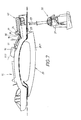
- This waiting position 11.1 is on the one hand by the spring force 18 and on the other hand by a in the figures determined by dot hatching securing means 40.
- the securing means 40 is made in the present case a ring segment 41 which is formed on a carrier 10 on the Cylinder segment 42 is rotatable in the circumferential direction.
- This twist is made by Head 43 of a screw 44 causes, in the installation of the carrier 10 in the door is accessible through a hole in the door side wall and by means of a Screwdriver can be screwed in and out.
- the aforementioned waiting position 11.1 is achieved in that an end piece 45 from Ring segment 41 clarified in a in Fig. 2 by the auxiliary line 45.1
- Initial rotational position is where the ring segment 42 at least partially the a lever end in the region of the counter bearing 16 overlaps.
- Fig. 2 shows Further, that the end of the return lever 11 between the two abutment points 16 is provided with a fork 46. This fork 46 sets the beginning mentioned breakthrough 14 in the carrier 10 in the region of this lever end continued.
- the clip 30 has a spring arm 31, which is formed on the plastic return lever 11 is integrally formed and having an end-side locking head 32.
- This Locking head 32 projects beyond the spring arm 31 with a blocking point 34 in the direction of Fork 46 and there has an inclined inlet slope 33.
- This Entry slope 33 is limited to the abutment point 16, from the blocking point 34.
- the securing segment 40 belonging to the ring segment 41 is rotated, which as already mentioned, is done by pressing the screw 44. It will the screw head 43 from the marked in Fig. 2 by the auxiliary line 43.1 Ausschraublage transferred to the recognizable from Fig. 10 screw 43.2. It a screwing movement takes place around the distance 47 recognizable from FIG. 10. As a result, the ring segment 41 becomes the angle 48 shown in FIG. 10 twisted. In this case, its end piece arrives from that shown in FIG. 2 and also in FIG. 10 clarified the initial rotational position 45.1 into the final rotational position marked 45.2. This will, because of the already mentioned double function of the securing means 40, two things.
- the handle-side bearing 26 is initially located on the cam 24 at the lever-side abutment point 16 at.
- "fixed bearing 36" If not the aforementioned inventive Rear handle would take place, this bearing 36 would be formed only non-positively. the bearing and counter bearing points 26, 16 would be only about the said spring force 18th of the lever connected to each other.
- this bearing 36 is in the invention characterized in that, as shown in FIG. 12, the clip 30 of this bearing 36 on the opposite side with its locking point 34 engages behind. So results in the invention, a positive locking bearing 36.
- the two diametrical cam 24th are back of the clip 30 and the front of the bearing 16 encapsulated and therefore rattle-free in the event of a crash.
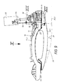
- the spring force 18 should not be sufficient to, as described above, in the release position 45.2 of the locking means 40 the return lever 11 from the Waiting position 11.1 of Fig. 7 in the end position 11.2 of Fig. 9 to transfer and while the clip 30 to put effective, it can also by a first operation 59 of the handle 20 happen.
- the resulting manual operating force is certainly sufficient to the described deformation of the spring arm 31 of Clip 30 and the rear handle of its locking head 32 on the cam-holding surface 27 to reach from the handle approach 23.
Landscapes
- Lock And Its Accessories (AREA)
Abstract
Description
- Fig. 1,
- einen ersten Bestandteil des erfindungsgemäßen Türaußengriffs, nämlich einen Träger, im Längsschnitt, wobei die Schnittlinie I - I in Fig. 2 gezeigt ist,
- Fig. 2
- die Rückansicht des Trägers in Blickrichtung des Pfeils II von Fig. 1,
- Fig. 3,
- in Vergrößerung und in perspektivischer Darstellung, den rechten Endbereich des Trägers von Fig. 1 oder 2,
- Fig. 4
- einen Längsschnitt durch den zweiten Bestandteil des erfindungsgemäßen Türaußengriffs, nämlich durch eine Handhabe, wobei die Schnittführung aus der Schnittlinie IV - IV von Fig. 5 zu erkennen ist,
- Fig. 5
- eine Rückansicht der in Fig. 4 gezeigten Handhabe, in Blickrichtung des Pfeils V von Fig. 4,
- Fig. 6,
- in einer der Fig. 1 und der Fig. 4 entsprechenden Darstellung, einen Längsschnitt durch den montierten Türaußengriff, wenn sich seine Bestandteile noch in einer Zwischenposition befinden,
- Fig. 7
- eine der Fig. 6 entsprechende Seitenansicht des in der Zwischenposition befindlichen Türaußengriffs von Fig. 6, vor Montage eines Schließzylinder-Turms,
- Fig. 8,
- in einer zur Fig. 3 analogen perspektivischen Darstellung, die bei dieser Zwischenposition sich ergebenden weiteren Details zwischen Griff und Träger,
- Fig. 9,
- in einer der Fig. 8 entsprechenden Darstellung, die Endposition des erfindungsgemäßen Türaußengriffs nach der Montage des Schließzylinder-Turms,
- Fig. 10
- eine Rückansicht des fertig montierten Türaußengriffs von Fig. 9 in Blickrichtung des Pfeils XI von Fig. 9,
- Fig. 11,
- wieder in einer zu Fig. 3 und 8 entsprechenden Darstellung, die perspektivische Ansicht des in Fig. 8 gezeigten Türaußengriffs, wenn sich seine Bestandteile in ihrer Endposition befinden, wobei, aus Gründen der Deutlichkeit, der bereits eingeführte und gesicherte Schließzylinder-Turm weggelassen wurde und
- Fig. 12,
- in Vergrößerung, einen Querschnitt durch einen besonderen Lagerbereich der Handhabe, wobei der Schnittverlauf durch die Schnittlinie XII - XII von Fig. 9 veranschaulicht ist.
- 10
- Träger
- 11
- Rückstellhebel an 10
- 11.1
- Wartestellung von 11 (Fig. 1 bis 7)
- 11.2
- Endstellung von 11 (Fig. 9)
- 12
- Schwenkachse für 11
- 13
- erster Durchbruch in 10 (Fig. 1)
- 14
- zweiter Durchbruch in 10 (Fig. 1)
- 15
- Lagersteg von 25 an 10 (Fig. 1, 2)
- 16
- Gegenlagerstellen an 11 (Fig. 1, 8)
- 17
- Schenkelfeder (Fig. 1, 2)
- 18
- Federkraft von 17 auf 11 (Fig. 1)
- 19
- Massenausgleichs-Gewicht (Fig. 1)
- 20
- Handhabe (Fig. 4)
- 20.1
- Ruhelage von 20 (Fig. 7, 9)
- 20.2
- Betätigungslage von 20 (Fig. 9)
- 21
- erstes Ende von 20 (Fig. 4)
- 22
- zweites Ende von 20 (Fig. 4)
- 23
- Ansatz an 22 (Fig. 4)
- 24
- Nocken an 23 (Fig. 7, 8)
- 25
- Lageraufnahme bei 21 für 15 (Fig. 1, 8)
- 26
- Lagerstelle an 24 (Fig. 8)
- 27
- Haltefläche an 24 (Fig. 8)
- 28
- Gegenkupplung für 58 (Fig. 4)
- 29
- Seitenfläche von 24 (Fig. 8)
- 30
- Clip (Fig. 3)
- 31
- Federarm von 30 (Fig. 3)
- 32
- Sperrkopf von 30 (Fig. 3)
- 33
- Einlaufschräge an 32 (Fig. 3)
- 34
- Sperrstelle an 32 (Fig. 3)
- 35
- loses Lager aus 15, 25 (Fig. 6)
- 36
- Festlager aus 16, 26 (Fig. 12)
- 37
- Gegenschulter an 50 für 49 (Fig. 7)
- 40
- Sicherungsmittel (Fig. 2, 3)
- 41
- Ringsegment von 40 (Fig. 3)
- 42
- Zylindersegment für 41 an 10 (Fig. 3)
- 43
- Kopf von 44 (Fig. 3)
- 43.1
- Ausschraubposition von 44 (Fig. 2, 3)
- 43.2
- Einschraubposition von 44 (Fig. 10)
- 44
- Schraube (Fig. 2, 3, 10)
- 45
- Endstück von 41 (Fig. 2, 3)
- 45.1
- Anfangsdrehlage von 45, Sperrlage von 40 (Fig. 2)
- 45.2
- Enddrehlage von 45, Freigabelage von 41 (Fig. 10)
- 46
- Gabelung von 11 zwischen 16 (Fig. 2)
- 47
- Einschraub-Strecke von 44 (Fig. 10)
- 48
- Drehwinkel zwischen 45.1 und 45.2 (Fig. 10)
- 49
- Sperrlappen an 42 für 50 (Fig. 10)
- 50
- Zylinderturm
- 51
- Pfeil der Einrenkbewegung von 21 (Fig. 1, 6)
- 52
- Pfeil der Einrenkbewegung von 22 (Fig. 1, 6)
- 53
- Pfeil der Einsteckbewegung von 50 in 10 (Fig. 7)
- 54
- Schließzylinder-Ausgang von 50 (Fig. 9, 10)
- 55
- Schloss
- 56
- flexible Verbindung zwischen 55 und 23
- 57
- erstes Kupplungsende an 56 für 23
- 58
- zweites Kupplungsende von 56 bei 55
- 59
- Pfeil der Handhaben-Betätigung (Fig. 9)
- 60
- Türaußenverkleidung (Fig. 1)
- 61
- Innenseite von 60 (Fig. 1)
- 62
- Außenseite von 60 (Fig. 1)
- 63
- Öffnung in 61 für 21 (Fig. 1)
- 64
- Öffnung in 60 für 22
Claims (12)
- Türaußengriff, insbesondere für Fahrzeuge
mit einem an der Innenseite (61) der Tür befestigten Träger (10), welcher einen federbelasteten (18) Rückstellhebel (11) aufweist,
mit einer Handhabe (20), die von der Türaußenseite (62) aus durch eine Einrenkbewegung (51, 52) im Träger (10) montierbar ist,
wobei das eine Ende (21) der Handhabe (20) mit dem Träger (10) ein loses Lager (35) bildet, während das andere Ende (22) der Handhabe (20) einen ins Türinnere weisenden Ansatz (23) aufweist
und der Ansatz (23) in einer bei Gebrauch des Türaußengriffs sich ergebenden Ruhelage (20.1) der Handhabe (20) mit dem Rückstellhebel (11) ein Festlager (36) erzeugt, wobei die Lagerstellen (26) vom Ansatz (23) der Handhabe (20) an Gegenlagerstellen (16) des Rückstellhebels (11) anliegen,
mit einem im Türinneren befindlichen Schloss (55), welches über eine Verbindung (56) an den Ansatz (23) der Handhabe (20) anschließbar (58, 28) ist,
und mit einem Sicherungsmittel (40), welches während der Einrenkmontage (51, 52) der Handhabe (20) den Rückstellhebel (11) vorübergehend in einer Wartestellung (11.1) fixiert, wobei die handhabenseitigen Lagerstellen (26) von den trägerseitigen Gegenlagerstellen (16) noch beabstandet sind,
dadurch gekennzeichnet , dass im Bereich der Lager- oder Gegenlagerstellen (26; 16) mindestens ein federnder Clip (30) angeordnet ist,
dass - in der Wartestellung (11.1) des Rückstellhebels (11) und nach vollzogener Einrenkmontage (51, 52) - der mindestens eine Clip (30) sich zwischen den Lager- und Gegenlagerstellen (26, 16) befindet
und dass - in einer Endstellung (11.2) des Rückstellhebels (11) - der mindestens eine Clip (30) mit den aneinanderliegenden Lager- und Gegenlagerflächen (26, 16) versehenen Teile (24, 27; 11) am Ansatz (23) der Handhabe (20) oder am Rückstellhebel (11) formschlüssig hintergreift. - Türaußengriff nach Anspruch 1, dadurch gekennzeichnet, dass der mindestens eine Clip (30) aus einem Federarm (31) mit endseitigem Sperrkopf (32) besteht.
- Türaußengriff nach Anspruch 2, dadurch gekennzeichnet, dass der Sperrkopf (32) eine Einlaufschräge (33) aufweist, welche von einer den Hintergriff der Teile (24, 27; 11) am Ansatz (23) der Handhabe (20) oder am Rückstellhebel (11) bewirkenden Sperrstelle (34) begrenzt ist,
dass die Einlaufschräge (33) beim Übergang des Rückstellhebels (11) aus der Wartestellung (11.1) in die Endstellung (11.2) gegen eine Steuerfläche (29) fährt, welche den Federarm (31) vorübergehend verbiegt,
dass die Steuerfläche (29) von einer quer verlaufenden Haltefläche (27) begrenzt ist, hinter welche der Sperrkopf (32) vom Clip (30) schnappt, wenn die Endstellung (11.2) erreicht ist. - Türaußengriff nach einem der Ansprüche 1 bis 3, dadurch gekennzeichnet, dass der Clip (30) am Ansatz (23) der Handhabe (20) angeformt ist.
- Türaußengriff nach einem der Ansprüche 1 bis 3, dadurch gekennzeichnet, dass der Clip (30) am trägerseitigen Rückstellhebel (11) angeformt ist.
- Türaußengriff nach einem der Ansprüche 1 bis 5, dadurch gekennzeichnet, dass am handhabenseitigen Ansatz (23) und/oder am trägerseitigen Rückstellhebel (11) zwei Clipse (30) angeordnet sind
und dass die Clipse (30) zueinander gegensinnig federnd und sperrwirksam sind. - Türaußengriff nach Anspruch 6, dadurch gekennzeichnet, dass die beiden Clipse (30) spiegelbildlich gleich ausgebildet sind und ein Clip-Paar bilden
und dass - in Längsrichtung des Rückstellhebels (11) gesehen - die Lagerstellen oder die Gegenlagerstellen (26, 16) im Zwischenraum zwischen dem Clip-Paar (30) angeordnet sind. - Türaußengriff nach Anspruch 3, 5, 6 oder 7, dadurch gekennzeichnet, dass der Clip (30) mit seinem Federarm (31) neben einer der beiden Gegenlagerstellen (16) sitzt
dass der Ansatz (23) einen seitlichen Nocken (24) aufweist, dessen äußeres Nockenende die Lagerstelle (26) bestimmt,
dass die Seitenfläche (29) des Nockens (24) die Steuerflächen vom Clip (30) bilden
und dass das innere Nockenende als Haltefläche (27) fungiert, welche in der Endstellung (11.2) des Rückhaltehebels (11) von der Sperrstelle (34) des Clip (30) hintergriffen wird. - Türaußengriff nach Anspruch 8, dadurch gekennzeichnet, dass der Rückstellhebel (11) an seinem die beiden Gegenlagerstellen (16) für das Clip-Paar (30) aufweisenden Hebelende eine Gabelung (46) aufweist
und dass nach der Einrenkmontage (51, 52) der Handhabe (20) der Ansatz (23) sich in der Gabelung (46) des Rückstellhebels (11) befindet und mit seinem Nocken-Paar (24) hinter den Gegenlagerstellen (16) vom Rückstellhebel (11) positioniert ist. - Türaußengriff nach einem oder Ansprüche 1 bis 9, dadurch gekennzeichnet, dass - in einer Freigabestellung (45.2) des Sicherungsmittels (40) - die Federbelastung (18) des Rückstellhebels (11) genügt, um die Clipse (30) so weit zu verformen, bis der Rückstellhebel (11) aus seiner Wartestellung (11.1) in seine Endstellung (11.2) gelangt.
- Türaußengriff nach einem der Ansprüche 1 bis 9, dadurch gekennzeichnet, dass - in einer Freigabestellung (45.2) des Sicherungsmittels (40) - eine erste manuelle Betätigung (59) der Handhabe (20) zur Verformung der Clipse (30) dient, um den Rückstellhebel (11) zwangsweise aus seiner Wartestellung (11.1) in seine Endstellung (11.2) zu überführen.
- Türaußengriff nach einem der Ansprüche 1 bis 11, dadurch gekennzeichnet, dass das Sicherungsmittel (40) eine Doppelfunktion aufweist und in seiner Freigabestellung (45.2) bezüglich des Rückstellhebels (11) zugleich zur Sicherung der Einstecklage eines Schließzylinder-Turms (50) oder einer Turm-Attrappe dient
und dass in der Wartestellung (11.1) des Rückstellhebels (11) der Schließzylinder-Turm (50) oder die Turm-Attrappe neben der Handhabe (20) in den Träger (10) einsteckbar (53) sind.
Applications Claiming Priority (2)
| Application Number | Priority Date | Filing Date | Title |
|---|---|---|---|
| DE10319153 | 2003-04-29 | ||
| DE10319153A DE10319153B3 (de) | 2003-04-29 | 2003-04-29 | Türaußengriff, insbesondere für Fahrzeuge |
Publications (3)
| Publication Number | Publication Date |
|---|---|
| EP1473423A2 true EP1473423A2 (de) | 2004-11-03 |
| EP1473423A3 EP1473423A3 (de) | 2007-02-21 |
| EP1473423B1 EP1473423B1 (de) | 2010-02-24 |
Family
ID=32981151
Family Applications (1)
| Application Number | Title | Priority Date | Filing Date |
|---|---|---|---|
| EP04005516A Expired - Lifetime EP1473423B1 (de) | 2003-04-29 | 2004-03-09 | Türaussengriff, insbesondere für Fahrzeuge |
Country Status (4)
| Country | Link |
|---|---|
| EP (1) | EP1473423B1 (de) |
| CN (1) | CN1291125C (de) |
| AT (1) | ATE458883T1 (de) |
| DE (2) | DE10319153B3 (de) |
Cited By (13)
| Publication number | Priority date | Publication date | Assignee | Title |
|---|---|---|---|---|
| WO2007134983A1 (de) * | 2006-05-18 | 2007-11-29 | Huf Hülsbeck & Fürst Gmbh & Co. Kg | Griffanordnung |
| WO2009034035A1 (en) * | 2007-09-11 | 2009-03-19 | Valeo S.P.A | Security handle for vehicles |
| ITMI20090008A1 (it) * | 2009-01-08 | 2010-07-09 | Valeo Spa | Maniglia di apertura per autoveicoli |
| WO2012045589A1 (de) | 2010-10-08 | 2012-04-12 | Huf Hülsbeck & Fürst Gmbh & Co. Kg | Türaussengriffvorrichtung |
| WO2012052274A1 (de) * | 2010-10-18 | 2012-04-26 | Huf Hülsbeck & Fürst Gmbh & Co. Kg | Vorrichtung zur befestigung eines wesentlichen bauelementes einer handhabe eines kraftfahrzeuges |
| CN102434027A (zh) * | 2011-12-14 | 2012-05-02 | 黄山市汽车电器股份公司 | 一种汽车门外侧把手结构 |
| US8469411B2 (en) | 2008-09-24 | 2013-06-25 | GM Global Technology Operations LLC | Door handle and latch assembly |
| EP2284339A3 (de) * | 2009-08-14 | 2013-11-06 | Skoda Auto a.s. | Sicherheitstürklinke |
| WO2015106784A1 (de) * | 2014-01-17 | 2015-07-23 | Huf Hülsbeck & Fürst Gmbh & Co. Kg | Kraftfahrzeugtürgriff |
| EP3020895A1 (de) * | 2014-11-13 | 2016-05-18 | Huf Hülsbeck & Fürst GmbH & Co. KG | Türgriff eines fahrzeugs mit einem zugmittel |
| CZ308003B6 (cs) * | 2016-05-13 | 2019-10-16 | Brano A.S. | Madlo dveří automobilu |
| WO2020012261A1 (en) * | 2018-07-09 | 2020-01-16 | Huf Hülsbeck & Fürst Gmbh & Co. Kg | Door handle assembly and related method |
| US11274475B2 (en) * | 2015-06-30 | 2022-03-15 | Huf Hülsheck & Fürst GmbH & Co. KG | Door-handle system for vehicles |
Families Citing this family (9)
| Publication number | Priority date | Publication date | Assignee | Title |
|---|---|---|---|---|
| DE102004058874A1 (de) * | 2004-12-06 | 2006-06-08 | Huf Hülsbeck & Fürst Gmbh & Co. Kg | Türaußengriff für ein Kraftfahrzeug |
| DE102005049142A1 (de) * | 2005-10-14 | 2007-04-19 | Volkswagen Ag | Bowdenzuganbindung mit integrierter Massensperre |
| DE102005049144A1 (de) * | 2005-10-14 | 2007-04-19 | Volkswagen Ag | Massensperre im Lagerbügel zur Blockierung eines Bowdenzuges |
| IT1390596B1 (it) * | 2008-07-07 | 2011-09-09 | Valeo Spa | Maniglia con dispositivo di sicurezza per veicoli |
| DE102009032324A1 (de) * | 2009-07-09 | 2011-01-13 | Huf Hülsbeck & Fürst Gmbh & Co. Kg | Türaußengriff, insbesondere für Fahrzeuge |
| US8632116B2 (en) | 2010-08-31 | 2014-01-21 | GM Global Technology Operations LLC | Anti-theft device for an access door |
| DE102011052960A1 (de) * | 2011-08-24 | 2013-02-28 | Huf Hülsbeck & Fürst Gmbh & Co. Kg | Türgriffanordnung eines Kraftfahrzeugs |
| CN103216159A (zh) * | 2013-04-24 | 2013-07-24 | 昌辉汽车电器(黄山)股份公司 | 一种汽车锁芯安装结构 |
| DE102017107229A1 (de) * | 2017-04-04 | 2018-10-04 | Huf Hülsbeck & Fürst GmbH & Co KG | Kraftfahrzeug-Türgriff-System |
Family Cites Families (5)
| Publication number | Priority date | Publication date | Assignee | Title |
|---|---|---|---|---|
| DE3628376A1 (de) * | 1986-08-21 | 1988-02-25 | Daimler Benz Ag | Tuergriffanordnung fuer tueren von kraftwagen |
| EP0646688B1 (de) * | 1993-10-05 | 1996-12-18 | YMOS AKTIENGESELLSCHAFT Industrieprodukte | Aussengriffanordnung für eine Tür, insbesondere eine Kraftfahrzeugtür |
| DE19619869C2 (de) * | 1995-05-27 | 2001-04-26 | Volkswagen Ag | Außenbetätigung für einen Fahrzeug-Türverschluß |
| DE19610200A1 (de) * | 1996-03-15 | 1997-09-18 | Valeo Deutschland Gmbh & Co | Türaußengriff |
| DE10057019A1 (de) * | 2000-11-17 | 2002-05-23 | Daimler Chrysler Ag | Türgriffanordnung für eine Fahrzeugtür |
-
2003
- 2003-04-29 DE DE10319153A patent/DE10319153B3/de not_active Expired - Fee Related
-
2004
- 2004-03-09 EP EP04005516A patent/EP1473423B1/de not_active Expired - Lifetime
- 2004-03-09 DE DE502004010793T patent/DE502004010793D1/de not_active Expired - Lifetime
- 2004-03-09 AT AT04005516T patent/ATE458883T1/de not_active IP Right Cessation
- 2004-04-29 CN CN200410042014.6A patent/CN1291125C/zh not_active Expired - Fee Related
Cited By (22)
| Publication number | Priority date | Publication date | Assignee | Title |
|---|---|---|---|---|
| US8540293B2 (en) | 2006-05-18 | 2013-09-24 | Huf Hulsbeck & Furst Gmbh & Co. Kg | Handle configuration |
| WO2007134983A1 (de) * | 2006-05-18 | 2007-11-29 | Huf Hülsbeck & Fürst Gmbh & Co. Kg | Griffanordnung |
| EP3327229A1 (de) * | 2006-05-18 | 2018-05-30 | HUF Hülsbeck & Fürst GmbH & Co. KG | Griffanordnung |
| WO2009034035A1 (en) * | 2007-09-11 | 2009-03-19 | Valeo S.P.A | Security handle for vehicles |
| US8746758B2 (en) | 2007-09-11 | 2014-06-10 | Valeo S.P.A. | Security handle for vehicles |
| US8469411B2 (en) | 2008-09-24 | 2013-06-25 | GM Global Technology Operations LLC | Door handle and latch assembly |
| ITMI20090008A1 (it) * | 2009-01-08 | 2010-07-09 | Valeo Spa | Maniglia di apertura per autoveicoli |
| EP2284339A3 (de) * | 2009-08-14 | 2013-11-06 | Skoda Auto a.s. | Sicherheitstürklinke |
| WO2012045589A1 (de) | 2010-10-08 | 2012-04-12 | Huf Hülsbeck & Fürst Gmbh & Co. Kg | Türaussengriffvorrichtung |
| US9435137B2 (en) | 2010-10-18 | 2016-09-06 | Huf Hulsbeck & Furst Gmbh & Co. Kg | Device for securing an essential component of a motor vehicle handle |
| WO2012052274A1 (de) * | 2010-10-18 | 2012-04-26 | Huf Hülsbeck & Fürst Gmbh & Co. Kg | Vorrichtung zur befestigung eines wesentlichen bauelementes einer handhabe eines kraftfahrzeuges |
| CN102434027A (zh) * | 2011-12-14 | 2012-05-02 | 黄山市汽车电器股份公司 | 一种汽车门外侧把手结构 |
| WO2015106784A1 (de) * | 2014-01-17 | 2015-07-23 | Huf Hülsbeck & Fürst Gmbh & Co. Kg | Kraftfahrzeugtürgriff |
| EP3020895A1 (de) * | 2014-11-13 | 2016-05-18 | Huf Hülsbeck & Fürst GmbH & Co. KG | Türgriff eines fahrzeugs mit einem zugmittel |
| US10145152B2 (en) | 2014-11-13 | 2018-12-04 | Huf Hülsbeck & Fürst Gmbh & Co. Kg | Door handle with removable cap |
| US10487548B2 (en) | 2014-11-13 | 2019-11-26 | Huf Hülsbeck & Fürst Gmbh & Co. Kg | Door handle of a vehicle with a tension means |
| US11274475B2 (en) * | 2015-06-30 | 2022-03-15 | Huf Hülsheck & Fürst GmbH & Co. KG | Door-handle system for vehicles |
| CZ308003B6 (cs) * | 2016-05-13 | 2019-10-16 | Brano A.S. | Madlo dveří automobilu |
| WO2020012261A1 (en) * | 2018-07-09 | 2020-01-16 | Huf Hülsbeck & Fürst Gmbh & Co. Kg | Door handle assembly and related method |
| CN112384670A (zh) * | 2018-07-09 | 2021-02-19 | 胡夫·许尔斯贝克和福斯特有限及两合公司 | 门把手组件及相关方法 |
| US20210324663A1 (en) * | 2018-07-09 | 2021-10-21 | Huf Hülsbeck & Fürst Gmbh & Co. Kg | Door handle assembly and related methods |
| US12305430B2 (en) * | 2018-07-09 | 2025-05-20 | Huf Hulsbeck & Furst Gmbh & Co. Kg | Door handle assembly and related methods |
Also Published As
| Publication number | Publication date |
|---|---|
| EP1473423A3 (de) | 2007-02-21 |
| CN1291125C (zh) | 2006-12-20 |
| EP1473423B1 (de) | 2010-02-24 |
| DE502004010793D1 (de) | 2010-04-08 |
| CN1542248A (zh) | 2004-11-03 |
| ATE458883T1 (de) | 2010-03-15 |
| DE10319153B3 (de) | 2004-11-18 |
Similar Documents
| Publication | Publication Date | Title |
|---|---|---|
| EP1473423B1 (de) | Türaussengriff, insbesondere für Fahrzeuge | |
| DE60020755T2 (de) | Griff für einen Kraftfahrzeugflügel mit verbesserten Blockierungsmitteln für ein Aussenteil | |
| DE102009043933B4 (de) | Kraftfahrzeugtürgriff | |
| DE102009029023A1 (de) | Kraftfahrzeugschloss | |
| EP1555363B1 (de) | Betätigungsvorrichtung für Türen oder Klappen an Fahrzeugen | |
| EP1766165A1 (de) | Vorrichtung zur betätigung eines in einer tür, einer klappe od. dgl. eingebauten schlosses, insbesondere bei einem fahrzeug | |
| DE102018108830A1 (de) | System aus einem Anbauteil und einem Halteelement | |
| DE4112132B4 (de) | Hebelwerk | |
| DE10320447A1 (de) | Kraftfahrzeugtürverschluss | |
| DE10126045A1 (de) | Türaußengriff-Bausatz, insbesondere für Fahrzeuge | |
| DE2916559A1 (de) | Lenkwellen-verriegelungsvorrichtung | |
| EP3392419A1 (de) | Befestigungssystem | |
| DE10151862A1 (de) | Vorrichtung zur Betätigung eines Verschlusses von Türen oder Klappen, insbesondere an Fahrzeugen | |
| EP1018589B1 (de) | Toleranzausgleich für eine kraftübertragende Verbindung zwischen einem Handgriff und einem Schlossauslösehebel | |
| DE69909676T2 (de) | Lenkradschlossvorrrichtung für eine Fahrzeuglenkung | |
| EP0520154B1 (de) | Anordnung eines Kabelschlosses an einem Zweiradrahmen | |
| EP3094799B1 (de) | Kraftfahrzeugtürgriff | |
| DE102011000224A1 (de) | Vorrichtung zur Befestigung eines wesentlichen Bauelementes | |
| DE102016215806A1 (de) | Rückenlehnenanordnung für ein Kraftfahrzeug, Kraftfahrzeug | |
| DE19922452B4 (de) | Als Abdeckelement an Fahrzeugen dienender beweglicher Karosserieteil | |
| EP0788920A2 (de) | Fahrpedaleinheit für Fahrzeuge | |
| WO2023194356A1 (de) | Anschlussgelenkanordnung | |
| DE602004000592T2 (de) | Verbindungsvorrichtung für ein Steuerkabelende | |
| EP1024240B1 (de) | Verriegelungsvorrichtung | |
| DE69401294T2 (de) | Einrichtung zur Befestigung eines Schlosses in seinem Gehäuse |
Legal Events
| Date | Code | Title | Description |
|---|---|---|---|
| PUAI | Public reference made under article 153(3) epc to a published international application that has entered the european phase |
Free format text: ORIGINAL CODE: 0009012 |
|
| AK | Designated contracting states |
Kind code of ref document: A2 Designated state(s): AT BE BG CH CY CZ DE DK EE ES FI FR GB GR HU IE IT LI LU MC NL PL PT RO SE SI SK TR |
|
| AX | Request for extension of the european patent |
Extension state: AL LT LV MK |
|
| PUAL | Search report despatched |
Free format text: ORIGINAL CODE: 0009013 |
|
| AK | Designated contracting states |
Kind code of ref document: A3 Designated state(s): AT BE BG CH CY CZ DE DK EE ES FI FR GB GR HU IE IT LI LU MC NL PL PT RO SE SI SK TR |
|
| AX | Request for extension of the european patent |
Extension state: AL LT LV MK |
|
| 17P | Request for examination filed |
Effective date: 20070317 |
|
| 17Q | First examination report despatched |
Effective date: 20070524 |
|
| AKX | Designation fees paid |
Designated state(s): AT BE BG CH CY CZ DE DK EE ES FI FR GB GR HU IE IT LI LU MC NL PL PT RO SE SI SK TR |
|
| GRAP | Despatch of communication of intention to grant a patent |
Free format text: ORIGINAL CODE: EPIDOSNIGR1 |
|
| GRAS | Grant fee paid |
Free format text: ORIGINAL CODE: EPIDOSNIGR3 |
|
| GRAA | (expected) grant |
Free format text: ORIGINAL CODE: 0009210 |
|
| AK | Designated contracting states |
Kind code of ref document: B1 Designated state(s): AT BE BG CH CY CZ DE DK EE ES FI FR GB GR HU IE IT LI LU MC NL PL PT RO SE SI SK TR |
|
| REG | Reference to a national code |
Ref country code: GB Ref legal event code: FG4D Free format text: NOT ENGLISH |
|
| REG | Reference to a national code |
Ref country code: CH Ref legal event code: EP |
|
| REG | Reference to a national code |
Ref country code: IE Ref legal event code: FG4D Free format text: LANGUAGE OF EP DOCUMENT: GERMAN |
|
| REF | Corresponds to: |
Ref document number: 502004010793 Country of ref document: DE Date of ref document: 20100408 Kind code of ref document: P |
|
| REG | Reference to a national code |
Ref country code: NL Ref legal event code: VDEP Effective date: 20100224 |
|
| PG25 | Lapsed in a contracting state [announced via postgrant information from national office to epo] |
Ref country code: PT Free format text: LAPSE BECAUSE OF FAILURE TO SUBMIT A TRANSLATION OF THE DESCRIPTION OR TO PAY THE FEE WITHIN THE PRESCRIBED TIME-LIMIT Effective date: 20100625 |
|
| PG25 | Lapsed in a contracting state [announced via postgrant information from national office to epo] |
Ref country code: PL Free format text: LAPSE BECAUSE OF FAILURE TO SUBMIT A TRANSLATION OF THE DESCRIPTION OR TO PAY THE FEE WITHIN THE PRESCRIBED TIME-LIMIT Effective date: 20100224 Ref country code: SI Free format text: LAPSE BECAUSE OF FAILURE TO SUBMIT A TRANSLATION OF THE DESCRIPTION OR TO PAY THE FEE WITHIN THE PRESCRIBED TIME-LIMIT Effective date: 20100224 Ref country code: FI Free format text: LAPSE BECAUSE OF FAILURE TO SUBMIT A TRANSLATION OF THE DESCRIPTION OR TO PAY THE FEE WITHIN THE PRESCRIBED TIME-LIMIT Effective date: 20100224 |
|
| REG | Reference to a national code |
Ref country code: IE Ref legal event code: FD4D |
|
| BERE | Be: lapsed |
Owner name: HUF HULSBECK & FURST G.M.B.H. & CO. KG Effective date: 20100331 |
|
| PG25 | Lapsed in a contracting state [announced via postgrant information from national office to epo] |
Ref country code: NL Free format text: LAPSE BECAUSE OF FAILURE TO SUBMIT A TRANSLATION OF THE DESCRIPTION OR TO PAY THE FEE WITHIN THE PRESCRIBED TIME-LIMIT Effective date: 20100224 Ref country code: MC Free format text: LAPSE BECAUSE OF NON-PAYMENT OF DUE FEES Effective date: 20100331 Ref country code: IE Free format text: LAPSE BECAUSE OF FAILURE TO SUBMIT A TRANSLATION OF THE DESCRIPTION OR TO PAY THE FEE WITHIN THE PRESCRIBED TIME-LIMIT Effective date: 20100224 Ref country code: GR Free format text: LAPSE BECAUSE OF FAILURE TO SUBMIT A TRANSLATION OF THE DESCRIPTION OR TO PAY THE FEE WITHIN THE PRESCRIBED TIME-LIMIT Effective date: 20100525 Ref country code: ES Free format text: LAPSE BECAUSE OF FAILURE TO SUBMIT A TRANSLATION OF THE DESCRIPTION OR TO PAY THE FEE WITHIN THE PRESCRIBED TIME-LIMIT Effective date: 20100604 Ref country code: EE Free format text: LAPSE BECAUSE OF FAILURE TO SUBMIT A TRANSLATION OF THE DESCRIPTION OR TO PAY THE FEE WITHIN THE PRESCRIBED TIME-LIMIT Effective date: 20100224 Ref country code: CY Free format text: LAPSE BECAUSE OF FAILURE TO SUBMIT A TRANSLATION OF THE DESCRIPTION OR TO PAY THE FEE WITHIN THE PRESCRIBED TIME-LIMIT Effective date: 20100224 Ref country code: RO Free format text: LAPSE BECAUSE OF FAILURE TO SUBMIT A TRANSLATION OF THE DESCRIPTION OR TO PAY THE FEE WITHIN THE PRESCRIBED TIME-LIMIT Effective date: 20100224 Ref country code: SE Free format text: LAPSE BECAUSE OF FAILURE TO SUBMIT A TRANSLATION OF THE DESCRIPTION OR TO PAY THE FEE WITHIN THE PRESCRIBED TIME-LIMIT Effective date: 20100224 |
|
| REG | Reference to a national code |
Ref country code: CH Ref legal event code: PL |
|
| PG25 | Lapsed in a contracting state [announced via postgrant information from national office to epo] |
Ref country code: SK Free format text: LAPSE BECAUSE OF FAILURE TO SUBMIT A TRANSLATION OF THE DESCRIPTION OR TO PAY THE FEE WITHIN THE PRESCRIBED TIME-LIMIT Effective date: 20100224 Ref country code: BG Free format text: LAPSE BECAUSE OF FAILURE TO SUBMIT A TRANSLATION OF THE DESCRIPTION OR TO PAY THE FEE WITHIN THE PRESCRIBED TIME-LIMIT Effective date: 20100524 Ref country code: CZ Free format text: LAPSE BECAUSE OF FAILURE TO SUBMIT A TRANSLATION OF THE DESCRIPTION OR TO PAY THE FEE WITHIN THE PRESCRIBED TIME-LIMIT Effective date: 20100224 |
|
| PLBE | No opposition filed within time limit |
Free format text: ORIGINAL CODE: 0009261 |
|
| STAA | Information on the status of an ep patent application or granted ep patent |
Free format text: STATUS: NO OPPOSITION FILED WITHIN TIME LIMIT |
|
| GBPC | Gb: european patent ceased through non-payment of renewal fee |
Effective date: 20100524 |
|
| PG25 | Lapsed in a contracting state [announced via postgrant information from national office to epo] |
Ref country code: DK Free format text: LAPSE BECAUSE OF FAILURE TO SUBMIT A TRANSLATION OF THE DESCRIPTION OR TO PAY THE FEE WITHIN THE PRESCRIBED TIME-LIMIT Effective date: 20100224 |
|
| 26N | No opposition filed |
Effective date: 20101125 |
|
| PG25 | Lapsed in a contracting state [announced via postgrant information from national office to epo] |
Ref country code: LI Free format text: LAPSE BECAUSE OF NON-PAYMENT OF DUE FEES Effective date: 20100331 Ref country code: BE Free format text: LAPSE BECAUSE OF NON-PAYMENT OF DUE FEES Effective date: 20100331 Ref country code: CH Free format text: LAPSE BECAUSE OF NON-PAYMENT OF DUE FEES Effective date: 20100331 |
|
| PG25 | Lapsed in a contracting state [announced via postgrant information from national office to epo] |
Ref country code: IT Free format text: LAPSE BECAUSE OF FAILURE TO SUBMIT A TRANSLATION OF THE DESCRIPTION OR TO PAY THE FEE WITHIN THE PRESCRIBED TIME-LIMIT Effective date: 20100224 |
|
| REG | Reference to a national code |
Ref country code: FR Ref legal event code: ST Effective date: 20110331 |
|
| PG25 | Lapsed in a contracting state [announced via postgrant information from national office to epo] |
Ref country code: GB Free format text: LAPSE BECAUSE OF NON-PAYMENT OF DUE FEES Effective date: 20100524 Ref country code: FR Free format text: LAPSE BECAUSE OF NON-PAYMENT OF DUE FEES Effective date: 20100426 |
|
| PG25 | Lapsed in a contracting state [announced via postgrant information from national office to epo] |
Ref country code: AT Free format text: LAPSE BECAUSE OF NON-PAYMENT OF DUE FEES Effective date: 20100309 |
|
| PG25 | Lapsed in a contracting state [announced via postgrant information from national office to epo] |
Ref country code: LU Free format text: LAPSE BECAUSE OF NON-PAYMENT OF DUE FEES Effective date: 20100309 Ref country code: HU Free format text: LAPSE BECAUSE OF FAILURE TO SUBMIT A TRANSLATION OF THE DESCRIPTION OR TO PAY THE FEE WITHIN THE PRESCRIBED TIME-LIMIT Effective date: 20100825 |
|
| PG25 | Lapsed in a contracting state [announced via postgrant information from national office to epo] |
Ref country code: TR Free format text: LAPSE BECAUSE OF FAILURE TO SUBMIT A TRANSLATION OF THE DESCRIPTION OR TO PAY THE FEE WITHIN THE PRESCRIBED TIME-LIMIT Effective date: 20100224 |
|
| REG | Reference to a national code |
Ref country code: DE Ref legal event code: R084 Ref document number: 502004010793 Country of ref document: DE |
|
| PGFP | Annual fee paid to national office [announced via postgrant information from national office to epo] |
Ref country code: DE Payment date: 20180213 Year of fee payment: 15 |
|
| REG | Reference to a national code |
Ref country code: DE Ref legal event code: R119 Ref document number: 502004010793 Country of ref document: DE |
|
| PG25 | Lapsed in a contracting state [announced via postgrant information from national office to epo] |
Ref country code: DE Free format text: LAPSE BECAUSE OF NON-PAYMENT OF DUE FEES Effective date: 20191001 |