EP1473398A2 - Steuereinrichtung für Knopfannähmaschine und Knopannähenverfahren mit dieser Einrichtung - Google Patents
Steuereinrichtung für Knopfannähmaschine und Knopannähenverfahren mit dieser Einrichtung Download PDFInfo
- Publication number
- EP1473398A2 EP1473398A2 EP04010354A EP04010354A EP1473398A2 EP 1473398 A2 EP1473398 A2 EP 1473398A2 EP 04010354 A EP04010354 A EP 04010354A EP 04010354 A EP04010354 A EP 04010354A EP 1473398 A2 EP1473398 A2 EP 1473398A2
- Authority
- EP
- European Patent Office
- Prior art keywords
- button
- needle
- holes
- sewing
- lower button
- Prior art date
- Legal status (The legal status is an assumption and is not a legal conclusion. Google has not performed a legal analysis and makes no representation as to the accuracy of the status listed.)
- Granted
Links
Images


Classifications
-
- D—TEXTILES; PAPER
- D05—SEWING; EMBROIDERING; TUFTING
- D05B—SEWING
- D05B3/00—Sewing apparatus or machines with mechanism for lateral movement of the needle or the work or both for making ornamental pattern seams, for sewing buttonholes, for reinforcing openings, or for fastening articles, e.g. buttons, by sewing
- D05B3/12—Sewing apparatus or machines with mechanism for lateral movement of the needle or the work or both for making ornamental pattern seams, for sewing buttonholes, for reinforcing openings, or for fastening articles, e.g. buttons, by sewing for fastening articles by sewing
- D05B3/14—Sewing apparatus or machines with mechanism for lateral movement of the needle or the work or both for making ornamental pattern seams, for sewing buttonholes, for reinforcing openings, or for fastening articles, e.g. buttons, by sewing for fastening articles by sewing perforated or press buttons
-
- D—TEXTILES; PAPER
- D05—SEWING; EMBROIDERING; TUFTING
- D05B—SEWING
- D05B19/00—Programme-controlled sewing machines
Definitions
- the present invention relates to a method of sewing upper and lower buttons having different numbers of holes with a cloth interposed therebetween and controlling a button sewing machine, and a button sewing method using the button sewing machine.
- buttons sewing machine for sewing an upper button onto a cloth and sewing a lower button onto the opposite side of the cloth with the cloth interposed between the upper and lower buttons.
- the upper and lower buttons generally have different numbers of holes, and are set in such a manner that the upper button has four holes and the lower button has two holes, and a sewing work is thus carried out, for example (see Figs. 5(a) and 5(b)).
- the button sewing machine according to the Patent Document 1 has such a structure as to separately support the upper button and the lower button movably in an orthogonal direction to the vertical moving position of a needle.
- the lower button is moved in any of the orthogonal directions in such a manner that the holes of the upper button and those of the lower button are coincident with each other in a vertical direction with the upper button fixed to a predetermined position.
- the needle is caused to penetrate through the coincident holes to carry out the sewing work.
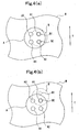
- the button sewing machine utilizes a single yarn chain stitch and each stitch is formed on the underside (outside) of a lower button B.
- the button sewing machine first makes a first set of the holes A1 and A2 of the upper button A, and makes the hole A1 of the upper button A coincident with the hole B1 of the lower button B and causes a needle to penetrate (to be located), thereby forming a first stitch, and subsequently, locates the needle onto the hole A2 of the upper button A and the other hole B2 of the lower button B, thereby forming a second stitch.
- an eighth final needle location is carried out into holes in the same combination as that of a seventh time (a seventh stitch), and knots and cuts a thread.
- a first cycle is ended.
- the two residual holes A3 and A4 of the upper buttons A are made as a second set, and the hole A3 of the upper button A is caused to be coincident with the hole B1 of the lower button B to penetrate (needle location), thereby forming a first stitch, and subsequently, the needle is located into the hole A4 of the upper button A and the other hole B2 of the lower button B, thereby forming a second stitch.
- an eighth final needle location is carried out into holes in the same combination as that of a seventh time (a seventh stitch), and knots and cuts the thread.
- a second cycle is ended.
- buttons are completely sewn.
- a thread T passes through the two holes B1 and B2 of the lower button B when all stitches are to be formed in the two cycles.
- the number of the threads T passing through the holes of the lower button is a double of the number of threads T passing through the two holes A1 and A2 of the upper button A. For this reason, when the needle penetrates through the holes of the lower button, a previous thread is stuck and is thus damaged, causing thread cutting. Consequently, the thread of the button is unsewn and a resewing work is required again. Thus, there is a problem in that a working efficiency is deteriorated.
- a first aspect of the invention is directed to a control apparatus forabuttonsewingmachine (100) comprisinganeedle (N) provided to be vertically movable, upper button holding means (2) for holding an upper button (A) having a plurality of holes which is to be sewn onto one surface side of a cloth (M), lower button holdingmeans (4) forholdingalowerbutton (B) having a different number of holes from that of the upper button which is sewn onto an opposite side of the upperbutton with the cloth interposed therebetween, driving means (for example, upper button holding portion driving means 3, a lower button holding means driving motor 52) for moving each of the upper button holding means and the lower button holding means independently in an orthogonal direction to a vertical moving path of the needle, and sewing operation control means (for example, a CPU 71) for controlling the driving means so as to control operations for sewing the upper button and the lower button, wherein the sewing operation control means can execute to sew the upper and lower buttons onto the cloth in a combination
- sewing operation control means for example
- the first sewing operation control and the second sewing operation control are combined with each other by the sewing operation control means, and the upper button and the lower button are thus sewn onto the cloth.
- the thread is laid over any two of the holes of the upper button and the lower button in the first sewing operation control, while the thread is laid over any two of the holes of the upper button and the cloth in the second sewing operation control. Accordingly, it is possible to decrease the number of the threads to be laid over any two of the holes of one of the buttons.
- a second aspect of the invention is directed to a control apparatus for a button sewing machine comprising a needle provided to be vertically movable, upper button holding means for holding an upper button having a plurality of holes which is to be sewn onto one surface side of a cloth, lower button holding means for holding a lower button having a different number of holes from that of the upper button which is to be sewn onto an opposite side of the upper button with the cloth interposed therebetween, driving means for moving each of the upper button holding means and the lower button holding means independently in an orthogonal direction to a vertical moving path of the needle, and sewing operation control means for controlling the driving means so as to control operations for sewing the upper button and the lower button, and serving to insert a thread through at least two specific holes of the upper button and two specific holes of the lower button, thereby sewing the upper button and the lower button onto the cloth, wherein the sewing operation control means can control the driving means in such a manner that the needle is inserted through one of the holes of the lower button when the needle is brought down and can control the driving means
- a third aspect of the invention is directed to a button sewing method using a button sewing machine for sewing an upper button and a lower button onto a cloth
- the button sewing machine comprising a needle provided to be vertically movable, upper button holding means for holding the upper button to be sewn onto the cloth with the needle, lower button holding means for holding the lower button to be sewn onto an opposite side of the cloth with respect to the upper button by means of the needle, and driving means for driving each of the upper button holding means and the lower button holding means independently in an orthogonal direction to a vertical moving path of the needle, wherein the driving means is controlled in such a manner that the needle is inserted through one of holes of the lower button when the needle is brought down and the driving means is controlled in such a manner that the needle is selectively inserted through one of the holes and the other hole of the lower button when the needle is subsequently brought down.
- a fifth aspect of the invention is directed to the control apparatus for a button sewing machine according to the first aspect of the invention, wherein it is possible to set a combination of the holes of the upper button and the lower button for carrying out the first sewing operation control, a combination of the holes of the upper button and the lower button for carrying out the second sewing operation control, and an order thereof.
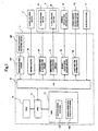
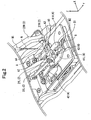
- a button sewing machine 100 comprises a sewing machine motor 1 capable of driving, in a vertical direction, a needle N (see Fig. 2) for sewing an upper button A (see Fig. 2) and a lower button B (see Fig. 2) onto a cloth M (see Fig. 4), a needle oscillating motor 51 capable of driving the needle N in a transverse direction (a needle oscillating direction), upper button holding means driving means (driving means) 3 capable of driving an upper button holding portion 2 (see Fig. 2) for holding the upper button A in a longitudinal direction and the transverse direction, a lower button holding means driving motor (driving means) 52 capable of driving lower button holding means 4 (see Fig. 2) for holding the lower button B in the longitudinal direction, an operation panel 6 capable of setting various operations related to a sewing work for the upper button A and the lower button B, and a control portion 7 for generally controlling them.
- a direction as to vertically move the needle N is set to be a Z-axis direction
- an orthogonal direction thereto is set to be an X-axis direction (a transverse direction)
- an orthogonal direction to both the Z-axis direction and the X-axis direction is set to be a Y-axis direction (a longitudinal direction).
- a direction indicated in an arrow of Fig. 2 is set to be a positive direction and a reverse direction thereto is set to be a negative direction.
- a so-called front button is set to be the upper button A and a button to be attached to the back side of the cloth M with respect to the front button, for example, a support button is set to be the lower button B.
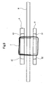
- the needle N is fixed to the lower end of a needle bar N1 which is provided almost above the positions of the cloth M onto which the upper button A and the lower button B are sewn by the button sewing machine 100 and is long in the Z-axis direction, for example. Moreover, a through hole through which a thread is to be inserted is formed on the tip portion of the needle N, which is not shown.
- the needle N can form a stitch when sewing the upper button A and the lower button B by a cooperation with a looper (not shown) provided almost under the positions of the cloth M in which the upper button A and the lower button B are sewn so as to be opposed to the needle N.
- the needle N is constituted to be reciprocally rockable in the X-axis direction (a needle oscillating direction) through a predetermined needle oscillating mechanism portion (not shown) by the driving operation of the needle oscillating motor 51.
- the cloth M is held between the upper and lower button holding means 2 and 4 by means (not shown) and is always brought into a constant condition with respect to the vertical moving path of the needle N, which is not shown.
- the upper button holding means 2 includes two upper button holding arms 22L and 22R to which two upper button holding members 21L and 21R interposing the upper button A from both sides in the X-axis direction are fixed, and can be moved in the X-axis and Y-axis directions through an upper button driving mechanism which is not shown, that is, an orthogonal direction to the vertical moving path of the needle N by the driving operation of the upper button holding means driving means 3.
- the upper button holding arms 22L and 22R are openably constituted in the X-axis direction by a button holding portion opening and closingmechanismwhich is not shown. Consequently, the upper button A can be freely held and released through the upper button holding members 21L and 21R.
- the upper button holding means 2 is constituted to be movable in the Z-axis direction by upper button holding means vertical movement driving means which is not shown.
- the lower button holding means 4 includes two lower button holding arms 41L and 41R interposing the lower button B from both sides in the X-axis direction, a spring 42 which is attached and fixed to the two lower button holding arms 41L and 41R and can apply a predetermined holding force for holding the lower button B with respect to the lower button holding arms 41L and 41R, and a guide member 43 for supporting the lower button B held by the two lower button holding arms 41L and 41R from below.
- the lower button holding means 4 can be moved in the Y-axis direction through a lower button driving mechanism which is not shown, that is, an orthogonal direction to the vertical moving path of the needle N by the driving operation of the lower button holding means driving motor 52.
- the control portion 7 is constituted by a CPU (Central Processing Unit) 71, an RAM (Random Access Memory) 72, an ROM (Read Only Memory) 73, an interface (I/F) 74, a driving circuit 75, an upper button X-axis driving circuit 76, an upper button holding means Y-axis driving circuit 77, a needle oscillation driving circuit 78 and a lower button driving circuit 79.
- a CPU Central Processing Unit
- RAM Random Access Memory
- ROM Read Only Memory
- I/F interface
- the ROM 73 is a programmable semiconductor memory, for example, and stores programs or control data related to various functions of the button sewing machine 100 which are to be executed by the CPU 71. More specifically, the ROM 73 stores a button sewing program 73a and a sewing operation control program 73b.
- the RAM 72 is constituted by a volatile semiconductor memory, for example, and includes a work area obtained by the CPU 71 and a storage area for temporarily storing various programs and control data which are read from the ROM 73 and can be executed by the button sewing machine 100.
- the CPU 71 expands a specified one of various programs stored in the ROM 73 into the work area in the RAM 72 and executes various processings in accordance with the programs.
- the CPU 71 executes a button sewing process of sewing the upper button A and the lower button B with respect to the predetermined position of the cloth M in accordance with the button sewing program 73a.
- the CPU 71 combines, as sewing operation control means, a first sewing operation control to be an operation control for forming a stitch in order to generate a crossover thread between the respective holes of the upper button A and the lower button B and a second sewing operation control to be an operation control for forming a stitch in order to generate a crossover thread between the holes of one of the buttons, for example, the upper button A, thereby executing to sew the upper button A and the lower button B onto the cloth M in accordance with the sewing operation control program 73b.
- a first sewing operation control to be an operation control for forming a stitch in order to generate a crossover thread between the respective holes of the upper button A and the lower button B
- a second sewing operation control to be an operation control for forming a stitch in order to generate a crossover thread between the holes of one of the buttons, for example, the upper button A, thereby executing to sew the upper button A and the lower button B onto the cloth M in accordance with the sewing operation control program 73b.
- the first sewing operation control is related to a sewing operation for moving the lower button holding means 4, that is, the lower button B by the lower button holding means driving motor 52 in such a manner that the thread (the needle N) inserted through one of the holes (for example, a hole B1) of the lower button B is inserted through the other hole (for example, a hole B2) of the lower button B in the next vertical motion of the needle N by the previous vertical motion of the needle N.
- the upper button holding means driving means 3 moves the upper button holding means 2, that is, the upper button A in such a manner that the thread is alternately inserted through one of the holes and the other hole of the upper button A in the former and latter vertical motions of the needle N.
- the second sewing operation control is related to a sewing operation for moving the lower button holding means 4, that is, the lower button B by the lower button holding means driving motor 52 in such a manner that the thread (the needle N) inserted through one of the holes (for example, the hole B1) of the lower button B is inserted through the same hole (for example, the hole B1) in the next vertical motion of the needle N by the previous vertical motion of the needle N.
- the upper button holding means driving means 3 moves the upper button holding means 2, that is, the upper button A in such a manner that the thread is alternately inserted through one of the holes and the other hole of the upper button A in the former and latter vertical motions of the needle N.
- the driving circuit 75 is connected to the sewing machine motor 1 and controls the driving operation of the sewing machine motor 1 based on a driving signal output from the CPU 71 and input through the interface 74 as a result of the calculation processing of the CPU 71.
- the upper button X-axis driving circuit 76 is connected to an X-axis driving motor 31 provided in the upper button holding means driving means 3 and inputs a driving signal to be the result of the calculation processing of the CPU 71 through the interface 74, thereby controlling the driving operation of the X-axis drivingmotor 31. Consequently, the X-axis driving motor 31 moves the upper button holding means 2 in the X-axis direction (an orthogonal direction to the vertical moving path of the needle N).
- the upper button holding means Y-axis driving circuit 77 connected to a Y-axis driving motor 32 provided in the upper button holding means driving means 3 inputs the driving signal to be the result of the calculation processing of the CPU 71 through the interface 74 so that the driving operation of the Y-axis driving motor 32 is controlled. Consequently, the upper button holding means 2 is moved in the Y-axis direction (the orthogonal direction to the vertical moving path of the needle N).
- the needle oscillation driving circuit 78 connected to the needle oscillating motor 51 inputs the driving signal to be the result of the calculation processing of the CPU 71 through the interface 74, thereby controlling the driving operation of the needle oscillating motor 51. Consequently, the needle oscillating motor 51 oscillates the needle N in the X-axis direction (the orthogonal direction to the vertical moving path of the needle N) through a predetermined needle oscillating mechanism portion.
- the lower button driving circuit 79 connected to the lower button holding means driving motor 52 inputs the driving signal to be the result of the calculation processing of the CPU 71 through the interface 74, thereby controlling the driving operation of the lower button holding means driving motor 52. Consequently, the lower button holding means driving motor 52 moves the lower button holding means 4 in the Y-axis direction (a perpendicular direction to the needle N).
- the operation panel (operating portion) 6 includes a predetermined switch for setting the combination of the holes of the upper button A and the lower button B in the first sewing operation control and the second sewing operation control to be carried out by the CPU 71 which will be described below and the number of sewing works and setting various operations related to the sewing works of the upper button A and the lower button B and for outputting them to the CPU 71.
- the operation panel 6 can set and store the combination of the setting every sewing cycle.
- well-known needle position detecting means NP is provided in the sewing machine 100 in relation to a main shaft, and the output of the needle position detecting means NP is input to a phase detecting circuit PS.
- the phase detecting circuit PS detects a phase to rise to a portion placed above the upper surface of the upper button A on which the tip of the needle N is held by the upper button holding means 2 or the vertical moving phase of the needle N descending to a portion placed under the upper surface of the upper button A, and outputs a signal to the CPU 71.
- buttons sewing process of the button sewing machine 100 will be described with reference to Figs. 3, 4, 8, 9 and 10.
- the upper button A and the lower button B shown in Fig. 4 are almost the same as the upper button A and the lower button B shown in Fig. 5. More specifically, any two of four holes A1 to A4 are arranged in two lines over the upper button A so as to be almost parallel, and two holes B1 and B2 are arranged in a line over the lower button B. Moreover, distances between the holes in the lines of the upper button A and the lower button B are almost equal to each other.
- the upper button A, the lower button B and the cloth M are set.
- the upper button A is supplied to the upper button holding means 2 manually or by a well-known button feeder, thereby holding the upper button A in the upper button holding means 2. More specifically, for example, the upper button holding means 2 is caused to hold the upper button A in such a manner that the direction of arrangement of any two of the holes A1, A2 (A3, A4) is almost parallel with the Y-axis direction (see Fig. 2).
- the lower button B is supplied to the lower button holding means 4 and the lower button holding means 4 is caused to hold the lower button B. More specifically, for example, the lower button holding means 4 is caused to hold the lower button B in such a manner that the direction of arrangement of the two holes B1 and B2 is almost parallel with the Y-axis direction (see Fig. 2).
- the cloth M onto which the buttons A and B are to be sewn is provided between the upper button A and the lower button B which are held by the upper button holding means 2 and the lower button holding means 4, respectively.
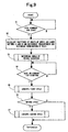
- the CPU 71 reads the button sewing program 73a from the ROM 73, expands the button sewing program 73a into the work area of the RAM 72 and executes the button sewing program 73a.
- the positions of the holes A1 to A4 of the upper button A and the holes B1 and B2 of the lower button B and distances therebetween are output by a predetermined calculation based on position data including the number of the holes of the upper button A and the lower button B and the central coordinates of each hole with respect to the center of each button which are input from the operation panel 6, and the combination of the holes into which the needle N is to be located is thus determined (S2).
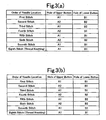
- the CPU 71 carries out a predetermined calculation processing based on the setting of the operation panel 6, thereby determining the order of the needle location of the needle N for the holes of the upper button A and the lower button B (S3). Consequently, the order of the needle location of the needle N shown in Fig. 3(a) is determined, for example.
- the CPU 71 reads the sewing operation control program 73b from the ROM 73 and executes the sewing operation control program 73b, thereby controlling the sewing operation of the button in such a manner that the needle N is located in accordance with the order of the needle location of the needle N which is determined as described above (S5, S6 and S7).
- first of all if a first cycle sewing work (S5), and then, a second cycle sewing work (S6) are set with a predetermined number of stitches in the combination of the two holes A1 and A2 of the upper button A and the two holes B1 and B2 of the lower button B, the second cycle sewing work is carried out with a predetermined number of stitches in the combination of the two residual holes A3 and A4 of the upper button A and the two holes B1 and B2 of the lower button B (57), thereby sewing the upper button A and the lower button B.
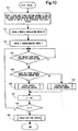
- the operations of the first and second cycle sewing works are controlled based on Fig. 10.
- the first cycle sewing work is carried out.
- the button is moved in such a manner that the hole A1 of the upper button A and the hole B1 of the lower button B are positioned on a line (S11), and furthermore, the needle N is moved in the X-axis direction in such a manner that the needle N is located into the holes A1 and B1 of the button (S12).
- the CPU 71 drives the sewing machine motor 1 to vertically move the needle N (S13), causes the needle N to penetrate through the hole A1 of the upper button A and the hole B1 of the lower button B and inserts the thread through the hole A1 of the upper button A and the hole B1 of the lower button B.
- the looper is operated synchronously with the vertical motion of the needle N to catch the thread inserted through the hole A1 of the upper button A and the hole B1 of the lower button B, thereby forming a thread loop below the lower button B (Fig. 8) (a step of sewing a first stitch).
- the CPU 71 decides whether a next sewing operation is the first sewing operation control (S15) and sets to carry out the first sewing operation control in the embodiment (S16).
- the upper and lower buttons A and B are moved in such a manner that the hole A2 of the upper button A and the hole B2 of the lower button B are positioned on a line, and furthermore, the needle N is moved in the X-axis direction in such a manner that the needle N is located into the holes A2 and B2 of the upper and lower buttons A and B. These operations are carried out while the tip of the needle N is positioned above the upper surface of the upper button A.
- the needle N penetrates through the hole A2 of the upper button A and the hole B2 of the lower button B to insert the thread through the hole A2 of the upper button A and the hole B2 of the lower button B.
- the looper is operated synchronously with the vertical motion of the needle N to catch the thread inserted through the hole A2 of the upper button A and the hole B2 of the lower button B, thereby forming a thread loop below the lower button B (Fig. 8) , and furthermore, forming a single yarn chain stitch by the thread loop thus formed and the thread loop formed at the first stitch (a step of sewing a second stitch).
- the CPU 71 adds "1" to a stitch formation number n by well-known stitch number count means (S17).
- the processing returns to the step S14 and it is then decided whether a next sewing operation is the first sewing operation control (S15).
- a second sewing operation control (S19) is provided as the next sewing operation.
- the driving operation of only the Y-axis driving motor 32 is controlled and only the upper button holding means 2 is moved to shift the button in such a manner that the hole A1 of the upper button A and the hole B2 of the lower button B are positioned on a line, and furthermore, the needle N is moved in the X-axis direction in such a manner that the needle N is located into the holes A1 and B2 of the upper and lower buttons A and B (a step of sewing a third stitch).
- the needle N penetrates through the hole A1 of the upper button A and the hole B2 of the lower button B to insert the thread through the hole A1 of the upper button A and the hole B2 of the lower button B. Consequently, the needle is continuously brought down to penetrate through the hole B2 of the lower button B in the same manner as in the previous second stitch.
- the looper When the needle N is lifted, subsequently, the looper catches the thread inserted through the hole A1 of the upper button A and the hole B2 of the lower button B to form a thread loop below the lower button B, and furthermore, a single yarn chain stitch is formed by the thread loop formed at the second stitch and the thread loop formed at the third stitch.
- the thread With a rise in the needle N, the thread is pulled in an upward direction through the hole B2 of the lower button B. Consequently, the single yarn chain stitch formed by the thread loop at the second stitch and the thread loop at the third stitch is provided on the underside of the cloth M through the hole B2.
- the CPU 71 executes the first sewing operation control (S16) in order to form a fourth stitch, thereby moving the upper and lower button holding means 2 and 4 to locate the needle N into the hole A2 of the upper button A and the hole B1 of the lower button B.
- the CPU 71 executes the second sewing operation control (S19) in order to form a fifth stitch, thereby moving only the upper button holding means 2 to locate the needle N into the hole A1 of the upper button A and the hole B1 of the lower button B.
- the CPU 71 executes the first sewingoperation control (S16) in such a manner that a sixth stitch is located into the hole A2 of the upper button A and the hole B2 of the lower button B and a seventh stitch is located into the hole A1 of the upper button A and the hole B1 of the lower button B.
- the CPU 71 decides whether n is equal to seven by counting the number of stitches (518), locates an eighth stitch to be a final needle location for the first cycle sewing work into the same holes A1 and B1 of the upper button A and the lower button B as those for the seventh stitch, and controls the tension of the thread to carry out a predetermined thread knotting operation, thereby cutting the thread by means of a thread cutting device which is not shown (S20).
- the second cycle sewing work (S7) is carried out to insert the thread through the two residual holes A3 and A4 of the upper button A and the two holes B1 and B2 of the lower button B, thereby sewing the upper button A and the lower button B in accordance with Fig. 10 in the same manner as in the first cycle sewing work.
- the CPU 71 executes to sew the upper button A and the lower button B onto the cloth M in the combination of the first sewing operation control and the second sewing operation control in the button sewing process.
- the thread is alternately inserted through the two holes A1 and A2 (B1 and B2) of the upper button A and the lower button B so that the thread is laid over the two holes A1 and A2 (B1 and B2) of the upper button A and the lower button B.
- the thread is laid over the two holes A1 and A2 of the upper button A and the cloth M so that the number of the threads to be laid over the two holes B1 andB2 of the lower button B can be decreased.
- the thread is inserted through each of the holes A1 and A2 (B1 and B2) of the upper button A and the lower button B with the progress of the button sewing operation.
- the second sewing operation control to be carried out by the CPU 71 it is possible to decrease the number of the threads to be laid over the two holes B1 and B2 of the lower button B. Therefore, it is possible to suppress the generation of such a sewing failure that the thread is not pulled up when it is to be inserted through each of the holes B1 and B2 of the lower button B or the needle sticks the thread inserted through the holes B1 and B2 of the lower button B.
- the lower button B is provided in such a manner that the thread is inserted continuously through the hole B2 of the lower button B in the second sewing operation control for the third stitch and the thread is inserted continuously through the hole B1 of the lower button B in the second sewing operation control for the fifth stitch.
- the second sewing operation control is not executed by using only one of the holes of the lower button B (for example, the hole B2) but using both of the holes B1 and B2 almost evenly. Consequently, the upper button A and the lower button B can be sewn properly. Accordingly, the impression of the stitch on the user canbe enhancedmore properly.
- theoperationpanel 6 capable of setting the number of sewing operations based on the second sewing operation control to be carried out by the CPU 71. Therefore, it is possible to easily regulate the number of the threads to be laid over the two holes A1 and A2 (B1 and B2) of the upper button A and the lower button B and the number of the threads to be laid over only the two holes A1. and A2 of the upper button A in accordance with the operation of the operation panel 6.
- each of the buttons is set in such a manner that the directions of arrangement of the two holes A1 and A2 and the two residual holes A3 and A4 in the upper button A are almost parallel with the direction of arrangement of the two holes B1 and B2 of the lower button B with respect to the upper button holding means 2 and the lower button holding means 4 in the embodiment, for example, which is not restricted.
- the conditions of the arrangement of the upper button A and the lower button B may be changed properly and optionally.
- the upper button holding means driving means 3 or the lower button holding means driving motor 52 maybe controlled in a sewing machine in which a needle oscillation is not carried out.
- any two of the four holes A1 to A4 are arranged in two lines over the upper button A and the two holes B1 and B2 are arranged in one line over the lower buttonB, and furthermore, the distances between the holes in each line of the upper button A and the lower button B are almost equal to each other, this is not restricted but the number of the holes to be formed on the upper button A and the lower button B, the distances between the holes and the arrangement of the holes can be changed properly and optionally.
- the CPU 71 can change the driving conditions of the upper button holding means driving means 3, the lower button holding means driving motor 52 and the needle oscillating motor 51 properly and optionally, thereby controlling the driving operations according to the number of the holes of the upper button A and the lower button B, the distances between the holes and the arrangement of the holes.
- the setting combination and order of the holes of the upper and lower buttons through which the needle penetrates may be directly provided through the operation panel 6 and data on the order shown in Fig. 3 (a) may be stored on a table, for example.
- the CPU 71 controls the X-axis and Y-axis driving motors 31 and 32 and the lower button holding means driving motor 52 in the stored order.
- the operation panel 6 provided with various switches has been illustrated as the operating portion in the embodiment, furthermore, this is not restricted but it is also possible to employ any structure in which the number of the sewing operations can be set based on the second sewing operation control through the CPU 71.
- the operation panel 6 may be a pressure sensitive touch panel in which a display screen and various switches are constituted integrally.
- the operating portion moreover, it is also possible to apply a mouse capable of moving a cursor displayed on a display screen to indicate a predetermined position on the display screen, thereby detecting the position thus indicated or to apply an operating pen capable of aligning a tip with a desirable position on the display screen, thereby detecting the position in place of the operation panel 6.
- the holes of the lower button are not filled with the thread. Consequently, a resistance can be reduced in the passage of the thread through the holes when the needle is lifted, and the thread is sufficiently pulled onto the cloth, resulting in a finish having a high sewing tightness.
- a commercial value can be enhanced. In the case in which a single yarn chain stitch is formed, particularly, the thread is not loosened so that the commercial value can be enhanced.
Landscapes
- Engineering & Computer Science (AREA)
- Textile Engineering (AREA)
- Sewing Machines And Sewing (AREA)
Applications Claiming Priority (2)
| Application Number | Priority Date | Filing Date | Title |
|---|---|---|---|
| JP2003126991A JP4167116B2 (ja) | 2003-05-02 | 2003-05-02 | ボタン付けミシン及びボタン縫付方法 |
| JP2003126991 | 2003-05-02 |
Publications (3)
| Publication Number | Publication Date |
|---|---|
| EP1473398A2 true EP1473398A2 (de) | 2004-11-03 |
| EP1473398A3 EP1473398A3 (de) | 2006-04-12 |
| EP1473398B1 EP1473398B1 (de) | 2010-10-27 |
Family
ID=32985608
Family Applications (1)
| Application Number | Title | Priority Date | Filing Date |
|---|---|---|---|
| EP04010354A Expired - Lifetime EP1473398B1 (de) | 2003-05-02 | 2004-04-30 | Steuereinrichtung für Knopfannähmaschine und Knopannähenverfahren mit dieser Einrichtung |
Country Status (5)
| Country | Link |
|---|---|
| EP (1) | EP1473398B1 (de) |
| JP (1) | JP4167116B2 (de) |
| KR (1) | KR101125905B1 (de) |
| CN (1) | CN100570037C (de) |
| DE (1) | DE602004029739D1 (de) |
Cited By (1)
| Publication number | Priority date | Publication date | Assignee | Title |
|---|---|---|---|---|
| CN101135088B (zh) * | 2006-08-31 | 2012-05-30 | 大和缝纫机制造株式会社 | 钮扣缝附方法及其缝纫机 |
Families Citing this family (8)
| Publication number | Priority date | Publication date | Assignee | Title |
|---|---|---|---|---|
| JP4578992B2 (ja) * | 2005-02-02 | 2010-11-10 | Juki株式会社 | ミシン |
| JP4660295B2 (ja) * | 2005-06-23 | 2011-03-30 | Juki株式会社 | ボタン付けミシン |
| JP5160030B2 (ja) * | 2005-10-14 | 2013-03-13 | Juki株式会社 | ボタン付けミシン及びボタン付け方法 |
| US20090106645A1 (en) * | 2007-10-17 | 2009-04-23 | Thinkingcraft, Inc. | Adaptive response/interpretive expression, communication distribution, and intelligent determination system and method |
| JP2010131056A (ja) * | 2008-12-02 | 2010-06-17 | Brother Ind Ltd | ボタン付けミシン及びボタン付け方法 |
| CN102493130A (zh) * | 2011-12-22 | 2012-06-13 | 天津应大股份有限公司 | 皮衣暗扣的缝制方法 |
| JP5477727B2 (ja) * | 2012-06-14 | 2014-04-23 | ヤマトミシン製造株式会社 | 根巻きボタン付けミシン |
| CN110130002A (zh) * | 2019-05-16 | 2019-08-16 | 东莞市名菱工业自动化科技有限公司 | 一种程序控制单线链式花样缝纫机 |
Family Cites Families (1)
| Publication number | Priority date | Publication date | Assignee | Title |
|---|---|---|---|---|
| JPH08117465A (ja) * | 1994-10-27 | 1996-05-14 | Juki Corp | ボタン付け装置 |
-
2003
- 2003-05-02 JP JP2003126991A patent/JP4167116B2/ja not_active Expired - Lifetime
-
2004
- 2004-04-27 KR KR1020040029029A patent/KR101125905B1/ko not_active Expired - Fee Related
- 2004-04-30 CN CNB2004100372706A patent/CN100570037C/zh not_active Expired - Lifetime
- 2004-04-30 EP EP04010354A patent/EP1473398B1/de not_active Expired - Lifetime
- 2004-04-30 DE DE602004029739T patent/DE602004029739D1/de not_active Expired - Lifetime
Cited By (1)
| Publication number | Priority date | Publication date | Assignee | Title |
|---|---|---|---|---|
| CN101135088B (zh) * | 2006-08-31 | 2012-05-30 | 大和缝纫机制造株式会社 | 钮扣缝附方法及其缝纫机 |
Also Published As
| Publication number | Publication date |
|---|---|
| EP1473398A3 (de) | 2006-04-12 |
| JP2004329407A (ja) | 2004-11-25 |
| CN100570037C (zh) | 2009-12-16 |
| KR101125905B1 (ko) | 2012-03-22 |
| JP4167116B2 (ja) | 2008-10-15 |
| KR20040094326A (ko) | 2004-11-09 |
| CN1542190A (zh) | 2004-11-03 |
| EP1473398B1 (de) | 2010-10-27 |
| DE602004029739D1 (de) | 2010-12-09 |
Similar Documents
| Publication | Publication Date | Title |
|---|---|---|
| KR101707158B1 (ko) | 재봉기 | |
| US7949421B2 (en) | Multi-needle type embroidery sewing machine and computer-readable storage medium including a computer control program for the multi-needle type embroidery sewing machine | |
| JP4364115B2 (ja) | ミシン | |
| EP1473398B1 (de) | Steuereinrichtung für Knopfannähmaschine und Knopannähenverfahren mit dieser Einrichtung | |
| JPH11267386A (ja) | 多頭式刺繍装置 | |
| KR100685060B1 (ko) | 단추를 다는 재봉틀 | |
| TWI534319B (zh) | Automatic sewing machine | |
| JPH09140974A (ja) | ミシン | |
| CN101387049B (zh) | 嵌条缝制缝纫机 | |
| EP1905879A2 (de) | Nähmaschine und Steuerung dafür | |
| JP7587938B2 (ja) | 縫製装置 | |
| US6298799B1 (en) | Sewing machine capable of tracing embroidery area | |
| JP2778210B2 (ja) | 止め縫いデータ作成装置 | |
| CN1814885B (zh) | 钉扣缝纫机 | |
| US6167824B1 (en) | Sewing machine having work holder | |
| US4945842A (en) | Embroidering sewing machine | |
| JPH10277281A (ja) | ベルトループ縫付けミシン | |
| JP2000271361A (ja) | ミシン | |
| JPH09140977A (ja) | ミシン | |
| JP2003071176A (ja) | 刺しゅうミシン | |
| JPH09140975A (ja) | ミシン | |
| JP4552300B2 (ja) | 刺繍データ作成装置および記録媒体 | |
| JPH0382497A (ja) | 自動縫製ミシン | |
| JP2006116201A (ja) | ミシン | |
| JPH06343779A (ja) | 自動刺繍ミシン |
Legal Events
| Date | Code | Title | Description |
|---|---|---|---|
| PUAI | Public reference made under article 153(3) epc to a published international application that has entered the european phase |
Free format text: ORIGINAL CODE: 0009012 |
|
| AK | Designated contracting states |
Kind code of ref document: A2 Designated state(s): AT BE BG CH CY CZ DE DK EE ES FI FR GB GR HU IE IT LI LU MC NL PL PT RO SE SI SK TR |
|
| AX | Request for extension of the european patent |
Extension state: AL HR LT LV MK |
|
| PUAL | Search report despatched |
Free format text: ORIGINAL CODE: 0009013 |
|
| AK | Designated contracting states |
Kind code of ref document: A3 Designated state(s): AT BE BG CH CY CZ DE DK EE ES FI FR GB GR HU IE IT LI LU MC NL PL PT RO SE SI SK TR |
|
| AX | Request for extension of the european patent |
Extension state: AL HR LT LV MK |
|
| 17P | Request for examination filed |
Effective date: 20060603 |
|
| 17Q | First examination report despatched |
Effective date: 20060929 |
|
| AKX | Designation fees paid |
Designated state(s): DE IT |
|
| GRAP | Despatch of communication of intention to grant a patent |
Free format text: ORIGINAL CODE: EPIDOSNIGR1 |
|
| GRAS | Grant fee paid |
Free format text: ORIGINAL CODE: EPIDOSNIGR3 |
|
| GRAA | (expected) grant |
Free format text: ORIGINAL CODE: 0009210 |
|
| AK | Designated contracting states |
Kind code of ref document: B1 Designated state(s): DE IT |
|
| REF | Corresponds to: |
Ref document number: 602004029739 Country of ref document: DE Date of ref document: 20101209 Kind code of ref document: P |
|
| PLBE | No opposition filed within time limit |
Free format text: ORIGINAL CODE: 0009261 |
|
| STAA | Information on the status of an ep patent application or granted ep patent |
Free format text: STATUS: NO OPPOSITION FILED WITHIN TIME LIMIT |
|
| 26N | No opposition filed |
Effective date: 20110728 |
|
| REG | Reference to a national code |
Ref country code: DE Ref legal event code: R097 Ref document number: 602004029739 Country of ref document: DE Effective date: 20110728 |
|
| PG25 | Lapsed in a contracting state [announced via postgrant information from national office to epo] |
Ref country code: IT Free format text: LAPSE BECAUSE OF FAILURE TO SUBMIT A TRANSLATION OF THE DESCRIPTION OR TO PAY THE FEE WITHIN THE PRESCRIBED TIME-LIMIT Effective date: 20101027 |
|
| REG | Reference to a national code |
Ref country code: DE Ref legal event code: R082 Ref document number: 602004029739 Country of ref document: DE Representative=s name: HOEGER, STELLRECHT & PARTNER PATENTANWAELTE MB, DE |
|
| REG | Reference to a national code |
Ref country code: DE Ref legal event code: R082 Ref document number: 602004029739 Country of ref document: DE Representative=s name: HOEGER, STELLRECHT & PARTNER PATENTANWAELTE MB, DE |
|
| REG | Reference to a national code |
Ref country code: DE Ref legal event code: R082 Ref document number: 602004029739 Country of ref document: DE Representative=s name: HOEGER, STELLRECHT & PARTNER PATENTANWAELTE MB, DE Ref country code: DE Ref legal event code: R081 Ref document number: 602004029739 Country of ref document: DE Owner name: JUKI CORP., TAMA-SHI, JP Free format text: FORMER OWNER: JUKI CORP., CHOFU, TOKIO/TOKYO, JP |
|
| PGFP | Annual fee paid to national office [announced via postgrant information from national office to epo] |
Ref country code: DE Payment date: 20230307 Year of fee payment: 20 |
|
| REG | Reference to a national code |
Ref country code: DE Ref legal event code: R071 Ref document number: 602004029739 Country of ref document: DE |