EP1472404B1 - Waschmaschine - Google Patents
Waschmaschine Download PDFInfo
- Publication number
- EP1472404B1 EP1472404B1 EP03729314A EP03729314A EP1472404B1 EP 1472404 B1 EP1472404 B1 EP 1472404B1 EP 03729314 A EP03729314 A EP 03729314A EP 03729314 A EP03729314 A EP 03729314A EP 1472404 B1 EP1472404 B1 EP 1472404B1
- Authority
- EP
- European Patent Office
- Prior art keywords
- washing machine
- valve
- opening
- pipe
- floating body
- Prior art date
- Legal status (The legal status is an assumption and is not a legal conclusion. Google has not performed a legal analysis and makes no representation as to the accuracy of the status listed.)
- Expired - Lifetime
Links
- 238000005406 washing Methods 0.000 title claims description 106
- 230000035515 penetration Effects 0.000 claims description 35
- XLYOFNOQVPJJNP-UHFFFAOYSA-N water Substances O XLYOFNOQVPJJNP-UHFFFAOYSA-N 0.000 claims description 27
- 238000009423 ventilation Methods 0.000 claims description 20
- 229920006328 Styrofoam Polymers 0.000 claims description 6
- 230000004888 barrier function Effects 0.000 claims description 6
- 239000008261 styrofoam Substances 0.000 claims description 6
- 239000013013 elastic material Substances 0.000 claims description 4
- 239000012530 fluid Substances 0.000 claims 1
- 239000003599 detergent Substances 0.000 description 25
- 230000000712 assembly Effects 0.000 description 10
- 238000000429 assembly Methods 0.000 description 10
- 230000008878 coupling Effects 0.000 description 3
- 238000010168 coupling process Methods 0.000 description 3
- 238000005859 coupling reaction Methods 0.000 description 3
- 239000003562 lightweight material Substances 0.000 description 3
- 239000000463 material Substances 0.000 description 2
- 239000000654 additive Substances 0.000 description 1
- 230000000996 additive effect Effects 0.000 description 1
- 238000011109 contamination Methods 0.000 description 1
- 238000013016 damping Methods 0.000 description 1
- 230000001419 dependent effect Effects 0.000 description 1
- 230000005489 elastic deformation Effects 0.000 description 1
- -1 for example Substances 0.000 description 1
- 238000003780 insertion Methods 0.000 description 1
- 230000037431 insertion Effects 0.000 description 1
- 238000000034 method Methods 0.000 description 1
- 239000004033 plastic Substances 0.000 description 1
- 230000008569 process Effects 0.000 description 1
- 230000009467 reduction Effects 0.000 description 1
- 238000000926 separation method Methods 0.000 description 1
- 238000009751 slip forming Methods 0.000 description 1
Images







Classifications
-
- D—TEXTILES; PAPER
- D06—TREATMENT OF TEXTILES OR THE LIKE; LAUNDERING; FLEXIBLE MATERIALS NOT OTHERWISE PROVIDED FOR
- D06F—LAUNDERING, DRYING, IRONING, PRESSING OR FOLDING TEXTILE ARTICLES
- D06F37/00—Details specific to washing machines covered by groups D06F21/00 - D06F25/00
- D06F37/26—Casings; Tubs
- D06F37/267—Tubs specially adapted for mounting thereto components or devices not provided for in preceding subgroups
-
- D—TEXTILES; PAPER
- D06—TREATMENT OF TEXTILES OR THE LIKE; LAUNDERING; FLEXIBLE MATERIALS NOT OTHERWISE PROVIDED FOR
- D06F—LAUNDERING, DRYING, IRONING, PRESSING OR FOLDING TEXTILE ARTICLES
- D06F37/00—Details specific to washing machines covered by groups D06F21/00 - D06F25/00
- D06F37/26—Casings; Tubs
-
- D—TEXTILES; PAPER
- D06—TREATMENT OF TEXTILES OR THE LIKE; LAUNDERING; FLEXIBLE MATERIALS NOT OTHERWISE PROVIDED FOR
- D06F—LAUNDERING, DRYING, IRONING, PRESSING OR FOLDING TEXTILE ARTICLES
- D06F39/00—Details of washing machines not specific to a single type of machines covered by groups D06F9/00 - D06F27/00
- D06F39/06—Arrangements for preventing or destroying scum
Definitions
- the present invention relates to a washing machine, and more particularly, to a washing machine with a structure to prevent bubbles generated inside the washing machine from being leaked to an outside.
- a washing machine has a drum equipped therein and washes laundry by rotating the drum.
- a tub for accommodating the drum, preliminarily storing washing water and feeding the stored washing water to the drum.
- the tub is connected with an inlet pipe, and the inlet pipe is connected with a detergent box so as to feed the detergent along the washing water to the tub.
- the bubbles generated by the detergent during a washing are introduced into the detergent box through the inlet pipe to contaminate the detergent box. Further, the bubbles may be leaked to the outside through the detergent box and may contaminate the washing machine and the surrounding thereof.
- the front loading type of washing machine causes more serious bubble generation, so that the leakage possibility of the generated bubbles increases.
- the detergent particularly generating a small amount of bubbles it is requested that the detergent particularly generating a small amount of bubbles be used.
- the use of such a detergent does not exclude the leakage possibility of the bubbles completely.
- JP 59 120 197A relates to a washing machine including a door for admitting laundry.
- JP 59 118 195A relates to a washing machine including a door for admitting laundry.
- the present invention is directed to a washing machine that substantially obviates one or more of the problems due to limitations and disadvantages of the related art.
- An object of the present invention is to provide a washing machine which enables to prevent bubbles generated in the drum and the tub from being leaked.
- a valve assembly for closing the opening and the pipe is installed in the opening to selectively close the pipe.
- a washing machine including: a tub installed inside a housing, for storing washing water, the tub including at least one opening and at least one pipe connected with the opening; a drum installed inside the tub and configured to wash laundry; and cutoff means for preventing bubbles generated in the drum and the tub from being leaked to an outside through the opening and the pipe.
- the opening is an inlet opening for feeding washing water from an external water feed source within the tub and the pipe is an inlet pipe connected with the inlet opening.
- the opening is a ventilation opening for inflowing external air into the tub and the pipe is a ventilation pipe connected with the ventilation opening.
- the cutoff means comprises a valve assembly installed in the opening, for selectively opening and closing the pipe such that the bubbles generated in the drum and the tub are not leaked to the outside.
- the valve assembly comprises: a valve installed in the opening and configured to ascend by the bubbles; and a guide provided in the opening, for guiding the movement of the valve.
- the valve assembly is provided in the opening and is installed within an extension pipe coupled with the pipe. Also, the valve is smaller than the opening and is larger than the diameter of the pipe.
- the pipe has a diameter that is partially reduced adjacent to the opening such that the pipe is stably closed by the valve. More preferably, the pipe has a rib inwardly extended from an inner circumferential surface thereof, or is a corrugated tube or a bellows tube having a plurality of corrugations.
- the valve is a floating body with a predetermined size, and preferably has a circular section.
- the guide is a plurality of ribs extended from the inner circumferential surface of the opening by a predetermined length.
- the rib is extended to have a predetermined interval from the valve, and has an extending portion extended from an end thereof, for supporting the valve.
- the valve comprises: a floating body with a predetermined size; and an elastic member enclosing the floating body.
- the floating body is made of Styrofoam and the elastic member is made of rubber.
- the floating body has a circular section.
- the valve has a beveled upper surface. More preferably, the valve is a conic type.
- the guide is a plurality of ribs extended from an inner circumferential surface of the opening by a predetermined length.
- the respective ribs are extended to have a predetermined interval from the valve, and have an extending portion extended from an end thereof, for supporting a lower portion of the valve.
- the valve further comprises an extending portion extending from a lower portion of the floating body and inserted between the extending portions of the respective ribs. More preferably, an interval between the valve and the rib is greater than an interval between the extending portion of the valve and a stepped portion of the rib.
- the valve comprises: a floating body having a convex surface; and an axial part extending from a lower portion of the floating body so as to be guided by the guide.
- the floating body is a hemispherical cell.
- the floating body further comprises a flange horizontally extended from an edge thereof.
- the axial part is a hollow shaft, and more preferably, comprises an outer circumferential surface covered with an elastic material layer.
- the guide comprises: a hub movably accommodating the axial part and supporting a lower portion of the floating body; and a plurality of ribs extended between an outer circumferential surface of the hub and an inner circumferential surface of the opening.
- the rib has a length which is constant at a location adjacent to the inner circumferential surface of the opening and increases at a location adjacent to the outer circumferential surface of the hub.
- the valve further comprises an elastic member provided on an outer circumferential surface of the axial part and positioned between the hub and the floating body. More preferably, the elastic member comprises a buffer protrusion formed at a lower end thereof.
- the valve assembly further comprises a plate member installed at a lower portion of the valve, for partially closing the opening such that the valve does not ascend by air flow.
- the plate member is a circular plate type, and the plate member has a size that is equal to or greater than the section of a lower portion of the valve.
- the plate member further comprises: at least one leg vertically extended from the lower surface thereof; and a hook formed at an end of the leg and fixed to a part of the guide.
- the cutoff means further comprises a joint assembly for fixing the pipe to the housing and partially closing the pipe such that the bubbles are not leaded to the outside.
- the joint assembly comprises: a penetration hole formed in the housing; and an extension pipe including a vertically extended inner barrier rib inserted into the penetration hole and coupled with the pipe.
- the penetration hole comprises a rib vertically formed at a circumference thereof, and the extension pipe comprises a flange configured to be in contact with the housing. Also, the penetration hole further comprises at least one cutout portion, and the extension pipe further comprises at least one hook formed at a predetermined interval on an outer circumferential surface thereof and inserted into the cutout portion.
- the extension pipe further comprises a plurality of protrusions formed on the flange, and a plurality of auxiliary penetration holes into which the plurality of protrusions are inserted are formed at a circumferential portion of the penetration hole.
- the protrusions further comprise a cylindrical type protrusion or a hemispherical type protrusion. More preferably, a cutout groove having a predetermined length is formed around the protrusion such that the protrusion is elastically connected with the flange.
- FIG. 1 is a side sectional view of a washing machine according to the present invention, and the washing machine is described with reference to FIG. 1 .
- the washing machine shown in FIG. 1 is the front loading type, but is nearly the same as the top loading type except that the tub 20 and the drum are laid. Accordingly, for the briefness of description, the invention will be described with reference to the washing machine of the front loading type, but it will be equally applied to the washing machine of the top loading type.
- the washing machine includes a housing 10, and a tub 20 and a drum 30 installed within the housing 10.
- the housing 10 is designed such that various kinds of elements are installed therein, and it protects these elements.
- a door 11 configured to open and close the entrance connected with the drum 10.
- a control panel 12 is installed on the housing 10. A user instructs the operation of the washing machine using the control panel 12, and puts laundry in or out of the drum 30 through the door 11.
- the tub 20 preliminarily stores washing water so as to supply washing water into the inner tub at a constant amount during the washing.
- the tub 20 is elastically fixed within the housing by using damping units 13a, 13b.
- a penetration hole 23 is formed at the center of the bottom face of the tub 20, and a drive shaft connected with the drum 30 is installed through the penetration hole 23.
- the tub 20 includes a plurality of openings 21, 22, 23 and pipes 21b, 22b, 23b connected with the openings 21, 22, 23. These openings 21, 22, 23 have extension pipes 21a, 22a, 23a, and the respective pipes 21 b, 22b, 23b can be more firmly connected to the extension pipes 21a, 22a, 23a.
- the tub 20 can be connected with various external devices that are necessary for operating the tub 20 by using the openings 21, 22, 23 and the pipes 21b, 22b, 23b.
- the tub 20 has an inlet opening 21 for inflowing washing water and an inlet pipe 21b connected to the inlet opening 21.
- the inlet pipe 21b is connected between the inlet opening 21 and a detergent box 21c, and is again extended to an external water supply source through the housing 10 from the detergent box 21 c.
- the washing water is supplied from the water supply source into the tub 20 via the inlet pipe 21b, the detergent box 21c and the inlet opening 21 along with the detergent.
- An outlet opening 23 is formed in the tub 20, and an outlet pipe 23b is connected to the outlet opening 23.
- the outlet pipe 23b is extended to an external drain unit. Used washing water is drained through the outlet opening 23 and the outlet pipe 23b.
- the drum 30 of the large capacitive washing machine is large in size, a child may enter the inside of the drum 30.
- a ventilation opening 22 is formed at the tub 20 such that the child breathe within the drum 30.
- a ventilation pipe 22b is installed to be connected to the ventilation opening 22 and communicates with the outside of the washing machine. Accordingly, the ventilation pipe 22b and the ventilation opening 22 function to supply external air into the tub 20, thereby preventing the child from being suffocated.
- the drum 30 accommodates laundry and is rotatably installed within the tub 20.
- the drum 30 includes a plurality of penetration holes 30a such that washing water is introduced from the tub 20.
- a plurality of baffles 30b are attached to an inner circumferential surface of the drum 30 such that the laundry is easily mixed.
- a drive part 40 is installed adjacent to the tub 20 and provides a power to the drum 30 so as to rotate the drum 30.
- the drive part 40 generally includes a motor, a clutch or the like, and is operatably connected by the drum 30 and the drive shaft as aforementioned.
- the washing machine of the present invention includes cutoff means for preventing the bubbles from being leaked to the outside of the washing machine.
- the outlet opening 23 and the outlet pipe 23b do not communicate with the outside, and they periodically drain the washing water. Since the possibility in the leakage of the bubbles through the outlet opening 23 and the outlet pipe 23b is small, the cutoff means is more effective in the inlet opening 21 and the ventilation opening 22. Accordingly, in the below, the cutoff means will be mainly described with embodiments applied to the inlet opening 21 and the ventilation opening 22, but it is apparent that these embodiments can be applied to the outlet opening 23.
- a valve assembly as the cutoff means is installed in the opening, and is configured to close the pipes connected to the opening so as to block the bubbles. This valve assembly will be in more detail described in the below along with various embodiments.
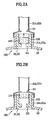
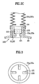
- FIGs. 2A to 2C are sectional views of a valve assembly according to a first embodiment of the present invention
- FIG. 3 is a plan view of the opening of the valve assembly according to the first embodiment of the present invention
- FIG. 4 is a sectional view showing a modified example of the first embodiment shown in FIGs. 2A to 2C .
- the valve assembly 100 includes a valve 110 installed in the inlet opening 21 and the ventilation opening 22 (hereinafter referred to as "opening"), and a guide 120 installed within the openings 21, 22.
- the valve assembly 100 may be installed directly on the inner circumferential surface of the openings 21, 22, but is preferably installed within the extension pipes 21a, 22a formed in the openings 21, 22 so as to operate stably.
- the valve 10 is configured to be movable up and down within the openings 21, 22, and the guide 120 is configured to guide the movement of the valve 110.
- the valve 110 should be smaller than the openings, more precisely, the extension pipes 21a, 22a so as to enable the flow of detergent and air through the openings 21, 22 and the smooth movement.
- the valve 110 is formed greater than the diameter of the inlet pipe 21b and the ventilation pipe 22b (hereinafter referred to as "pipes") so as to close the pipes 21b, 22b.
- the diameters of the pipes 21b, 22b may be designed smaller than the size of the valve 110 such that the pipes 21b, 22b are closed by the valve 110.
- the pipes 21b, 22b can have a rib 24 placed adjacent to the openings 21, 22.
- the rib 24 is, as shown in the drawings, extended radially and inwardly from the inner circumferential surface of the pipes 21b, 22b.
- the pipes 21b, 22b may be a corrugated pipe or a bellows pipe. These pipes have a plurality of corrugations 24a, and these corrugations 24a result in the reduction of the diameter like the aforementioned rib 24. Accordingly, the valve 110 is in contact with the rib 24 or the corrugations 24a during the movement thereof, thereby closing the pipes 21b, 22b more firmly.
- the valve 110 includes a floating bodying body with a predetermined size.
- the valve 110 is made of a lightweight material, for example, Styrofoam, and can thus ascend by the bubbles.
- the valve 110 is formed at least larger than the pipes 2 1 b, 22b, and is preferably configured to have a circular section to correspond to the shapes of the extension pipes 21a, 22a and the pipes 21b, 22b.
- the guide 120 as shown in FIG. 3 , includes a plurality of ribs extended by a predetermined length from the inner circumferential surface of the openings 21, 22.
- the ribs 120 may be formed more stably on the inner circumferential surface of the extension pipes 21a, 22a. These ribs 120 are extended to have a predetermined interval from the valve 110, thereby capable of movably guiding the valve 110. Also, each of the ribs 120 includes an extending portion 121 radially and inwardly from an end thereof. The extending portion 121 is protruded from the rib 120 to form a stepped portion. Accordingly, the extending portion 121 supports the valve 110 such that the valve 110 is located within the openings 21, 22 and the extension pipes 21a, 22a.
- the valve 120 may ascend even by air flow through the openings 21, 22 as well as the bubbles.
- the air within the tub 20 and the drum 30 flows fast through the openings 21, 22 by the movement of the door 11.
- the valve 110 closes the pipes 21b, 22b.
- the closing of the pipes 21b, 22b allows the tub 20 and the drum 30 to be sealed, so that a pressure is instantly generated within the tub 20 and the drum 30.
- the generated pressure causes the door not to be closed.
- the plate member 130 closes the openings 21, 22 and the extension pipes 21a, 22a such that the air flow does not reach directly the valve 110.
- the plate member 130 since the plate member 130 partially closes the openings 21, 22 and the extension pipes 21a, 22a, it permits the smooth supply of the washing water in the inlet opening and the smooth air flow in the ventilation opening 22.
- the plate member 130 is preferably a circular plate type to approximately correspond with the shape of the valve 110. Also, in order to block an abrupt air flow and detour the air flow from the valve 110, it is desirable that the size of the circular plate member 130 be equal to or greater than the size of the lower side of the valve 110 facing with the circular plate member 130.
- the plate member 130 is mounted on an extending portion 121 of the rib, so that the valve 110 is supported by the plate member 130.
- the plate member 130 further includes legs 131 extending from the lower surface thereof and hooks 132 formed at ends of the legs 131.
- the legs 131 are, as shown in FIG. 6A , extended parallel to the ribs 120, and are supported such that the plate member 130 does not shake by the ribs 120.
- the hook 132 is latched by a lower end of the rib 120, thereby fixing the plate member 130 to the rib 120.
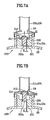
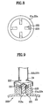
- FIGs. 7A and 7B , and FIG. 8 A valve assembly according to a second embodiment of the present invention is shown in FIGs. 7A and 7B , and FIG. 8 , and the second embodiment will be described in detail with reference to these drawings.
- a valve assembly 200 of the second embodiment includes a valve 210 installed within openings 21, 22 and a guide 220.
- the valve 210 and the guide 220 are installed within extension pipes 21 a, 22a.
- the basic characteristics of the valve 210 and the guide 220 are the same as those of the valve 110 and the guide 120 according to the first embodiment.
- the valve 210 is guided by the guide 210 and is movable up and down.
- the size of the valve 210 and the diameters of the pipes 21b, 22b are properly designed such that the pipes 21b, 22b are closed by the valve 210.
- the pipes 21b, 22b may have a rib 24 such that the valve 210 is latched with ease.
- the pipes 21 b, 22b may have a plurality of corrugations 24a as shown in FIG. 2C .
- the valve 210 includes a floating body 211 with a predetermined size, and an elastic member 212 enclosing the floating body 211.
- the floating body 211 can be made of Styrofoam that is a lightweight material, and has a circular section to be appropriate for the circular type of openings 21, 22, the extension pipes 21a, 22a, and the pipes 21b, 22b. Since this floating body 211 is made of a lightweight and weak material (i.e., Styrofoam), it may be gradually fractured with being in contact with the pipes 21 b, 22b and the guide 220 during the ascent or descent by the bubbles.
- Styrofoam a lightweight and weak material
- the elastic member 212 preferentially protects the floating body 211, and may be preferably made of rubber. Since the elastic member 212 absorbs impact, it reduces the noise generated by the movement of the valve 210.
- At least one beveled surface is preferably formed at an upper side of the valve 210. In other words, the beveled surface is formed at the upper side of the floating body 211, and a beveled surface is formed at the same location of the elastic member 212 so as to enclose the floating body 211. This is because, although the valve 10 ascends obliquely by some degree, the beveled surface enables the valve 210 to precisely close the pipes 21b, 22b while being guided by the pipes 21b, 22b.
- beveled surfaces are continuously formed around the valve 210, which enable to guide the floating body 211 and precisely close the pipes 21b, 22b although the valve is oblique in any direction. As shown in the drawings, these continuous beveled surfaces substantially permit the valve 210 to have a conic structure.
- the guide 220 is substantially similar to the guide 120 of the first embodiment.
- the guide 220 includes a plurality of ribs 220 extended from the inner circumferential surfaces of the openings 21, 22 or the extension pipes 21a, 22a so as to have a predetermined interval from the valve 210.
- each of the ribs 220 has an extending portion 221 radially extended from an end thereof, and the valve 20 is supported by the extending portion 221.
- a plate member 230 is installed below the valve 210.
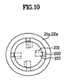
- the plate member 230 includes legs 231 extended from the lower side thereof and hooks 232 formed at ends of the legs 231 and fixed to lower ends of the ribs 220 like the first embodiment. Since the plate member 230 is the same as the plate member 130 of the first embodiment, its detailed description will be omitted.
- the floating body 211 may further include an extending portion 211 a vertically extended from a lower side thereof.
- the extending portion 211a is inserted between the extending portions 221, and thereby is supported and guided by the extending portions 221.
- a penetration hole 230a for the extending portion 211a is formed in the plate member 230 as shown in FIG. 10 , and the extending portion 211a is guided and supported even by the penetration hole 230a. Accordingly, the whole of the valve 210 can ascend or descend more stably by the extending portion 211 a.
- the interval (t2) between the valve 210 and the rib 220 is preferably greater than the interval (t1) between the extending portion 211a and the extending portion 221.
- valve assembly according to a third embodiment of the present invention will be described in more detail.
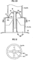
- FIGs. 11A and 11B are sectional views of a valve assembly according to a third embodiment of the present invention
- FIG. 12 is a plan view of the valve assembly according to the third embodiment of the present invention.
- a valve assembly 300 of the third embodiment includes a valve 210 installed within openings 21, 22 or extension pipes 21a, 22a, and a guide 220. Since general characteristics related with the valve 210, the guide 220 and the extension pipes 21a, 22a are described in the foregoing first and second embodiments, detailed description thereof will be omitted.
- the valve 310 includes a floating body 311 and an axial part 312 extended from the bottom surface of the floating body 311.
- the floating body 311 is formed to have a convex surface as a whole as shown in FIGs. 11A and 11B .
- the convex surface is guided by the inner circumferential surface of the pipes 21b, 22b during its ascent, thereby permitting the floating body 311 to precisely and easily close the pipes 21b, 22b.
- the floating body 311 is preferably a hemispherical shell having a convex curvature as a whole so as to reduce its weight.
- the floating body 311 is made of Styrofoam that is a lightweight material.
- the floating body 311 may be made of plastic material owing to its lightweight property. Accordingly, the strength of the floating body 311 is reinforced, and endurance is also enhanced. In addition, since the floating body 311 that is the hemispherical shell has a space formed therein, it is subject to a larger buoyancy from the bubbles and thus ascends with ease. In the meanwhile, it is desirable that the floating body 311 further include a flange 311 a horizontally extended from an edge thereof so as to be stably in contact with the pipes 21a, 21b. The axial part 312 is guided by the guide 320 so that the valve 310 moves stably. In order to reduce the weight of the valve 310, the axial part 312 is preferably formed in a hollow shaft.
- the guide 320 includes a hub 321 arranged within the openings 21, 22 and the extending portions 21a, 22a, and ribs 322 connecting the hub 321 with the openings 21, 22/the extension pipes 21a, 22a.
- the hub 321 accommodates the axial part 312 movably, and supports the floating body 311 so as to be located within the extension pipes 21a, 22a.
- the ribs 22 are substantially extended from the outer circumferential surface of the hub 321 to the inner circumferential surfaces of the openings 21, 22 and the extension pipes 21a, 22a.
- the length of the rib 322 placed around the hub 321 is formed preferably longer than other portions. Accordingly, the bonding length between the hub 321 and the ribs 321 is lengthened, so that the ribs 321 are firmly connected with the hub 321.
- a plate member 330 is installed below the valve 310. Since the general characteristics of the plate member 330 are described in the first and second embodiments, its detailed description will be omitted.
- the plate member 330 is mounted on the ribs 322.
- the ribs adjacent to the inner circumferential surfaces of the openings 21, 22 and the extension pipes 21a, 22a have a constant length.
- the plate member 330 further includes a penetration hole 330b and a plurality of slots 330a for a long rib 323 around the hub so as to be mountable on the rib 322.
- the plate member 330 includes legs 331 extended from the lower side thereof and hooks 332 formed at ends of the legs 331. As shown in FIGs.
- the legs 331 are extended to have a constant interval from the ribs 322, and are supported on the outer circumferential surface of the hub such that the plate member 330 does not shake. Also, the hooks 332 are latched with lower ends of the hub 321 to fix the plate member 330 to the hub 321.
- the legs 331 are extended parallel to the ribs 322 and are supported by the ribs 322 such that the plate member 330 does not shake. In addition, the hooks 332 are latched with lower ends of the ribs 322 to fix the plate member 330 to the ribs 322.
- the valve 310 may further include an elastic member 313 provided on the outer circumferential surface of the axial part 312.
- the elastic member 313 has a ring shape substantially, and is installed to be in contact with the inner surface of the floating body 311.
- the elastic member 313 is interposed between the upper side of the hub 321 and the inner surface of the floating body 311. Accordingly, the elastic member 313 elastically supports the valve 310 so as to prevent impact and noise.
- a protrusion 313a is further formed at a lower end of the elastic member 313. The protrusion 313a is easily deformed when it is in contact with the upper side of the hub 321, thereby preventing impact and noise more effectively.
- an elastic material layer 312a can be formed on the outer circumferential surface of the axial part 3112.
- the elastic material layer 3 absorbs the impact between the hub 321 and the axial part 312 during the elevation of the valve 310, thereby capable of reducing noise remarkably.
- a joint assembly 400 is installed in order to fix the pipes 21b, 22b to the housing 10 and connect the pipes 21b, 22b with external pipes if necessary. Since the joint assembly 400 is located at a boundary of the washing machine, e.g., in the housing 10, the bubbles can be blocked lastly and perfectly at the joint assembly 400. Accordingly, the joint assembly 400 is further included in the present invention as the cutoff means and will be described in more detail.
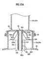
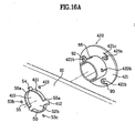
- FIGs. 15A and 15B are sectional view and front view of a joint assembly according to the present invention.
- the joint assembly 400 of the present invention includes a penetration hole 410 formed in the housing 10 and an extension pipe 420 inserted into the penetration hole 410.
- the extension pipe 420 is connected with the pipes 21b, 22b and is also inserted into the penetration hole 410, thereby fixing the pipes 2 1 b, 22b to the housing 10.
- the housing 10 is extended to be coupled with an external pipe outside the washing machine, so that the pipes 21b, 22b are connected with the external pipe.
- a vertically extended inner barrier rib 420a is formed within the extension pipe 420 as shown in the drawings.
- the inner barrier rib 420a results in partially closing the extension pipe 420 and partially closing the pipes 21b, 22b connected to the extension pipe 420. Accordingly, no matter how much the amount of the generated bubbles is, since the amount of the bubbles leaked from the valve assemblies 100, 200, 300, 400 is small, the inner barrier rib 420a prevents the bubbles from being leaked.
- a rib 411 for guiding the extension pipe 420 is formed along the circumference of the penetration hole 410.
- a flange 421 is formed on the outer circumferential surface of the extension pipe 410, and is in contact with the housing 10 placed around the penetration hole 410 so as to support the extension pipe 420.
- the penetration hole 410 includes at least one cutout portion 412 formed in the rib 412. The cutout portion 412 is extended by a predetermined length to the housing 10 located around the penetration hole 410.
- At least one hook 422 is formed on the outer circumferential surface of the extension pipe 420.
- the hook 422 consists of two ribs that are normal to and connected with each other, and it has an angle shape substantially.
- the hook 422 includes a first member 422a extended along the length direction of the extension pipe 420, and a second member 422b extended perpendicularly to the first member 422a.
- the hook 422 is inserted through the cutout portion 412 and latched to the rib 411.
- auxiliary penetration holes 413 Around the penetration hole 410, there are formed a plurality of auxiliary penetration holes 413.
- the protrusions include a cylindrical protrusion 421 a and a hemispherical protrusion 421b, and they are formed at a predetermined interval.
- a cutout groove 421c having a predetermined length is formed in the flange around the protrusions 421a, 421b, and permits the protrusions 421a, 421 b to be elastically connected.
- a kind of leg connecting the protrusions 421a, 421b with the flange 421 is formed by the cutout grooves 421c.
- the leg is elastically deformed such that the protrusions 421a, 421 b are easily inserted into the auxiliary penetration holes 413.
- the extension pipe 420 is inserted into the penetration hole 410 while the hook 422 is inserted into the cutout portion 412.
- the protrusions 421a, 421b are not inserted into the auxiliary penetration holes 413, and are pushed backward by the elastic deformation of the leg with being in contact with the housing 10.
- the hook 422 is engaged with the rib 411.
- the first member 422a of the hook 422 is latched to a side portion of the rib 411 to thereby determine the coupling position of the extension pipe 420.
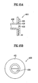
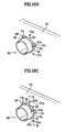
- the second member 422b is latched to an end of the rib 411 to prevent the separation of the extension pipe 420. Also, the protrusions 421 a, 421 b pushed backward during the rotation of the extension pipe 420 permit the extension pipe 420 to rotate smoothly. If the protrusions 421a, 421b reach the corresponding auxiliary penetration holes 413, the protrusions 421a, 421b are restored and inserted into the auxiliary penetration holes 413. As shown in FIG. 17A , the cylindrical protrusion 421a is firmly fixed to the housing 10 so as not to rotate the extension pipe 420 arbitrarily. Also, as shown in FIG.
- the hemispherical protrusion 421b separates the flange 421 from the housing 10 to thereby prevent the vibration of the washing machine from being transferred to the flange 421 during its operation. Accordingly, the pipes 21b, 22b are not separated from the extension pipe 420 by the vibration of the washing machine.
- the joint assembly 400 can prevent leakage of bubbles and be coupled firmly to the housing 10 without a coupling member.
- a user instructs to wash the laundry using the control panel 12.
- washing water is fed into the tub 20 along with detergent from an external water supply point via the inlet pipe 21b, the detergent box 21c and the inlet opening 21.
- the valves 110, 210, 310 are placed on the extending portions 121, 221 of the ribs 120, 220, 320 or the hub 321, and the washing water and the detergent flow between the valves 110, 210, 310 and the inlet opening 21/the extension pipe 21a and are then fed into the tub 20.
- air introduced into the ventilation pipe 21b can be fed into the tub 20 and the drum 30 through a space between the valves 110, 210, 310 and the ventilation opening 22/the extension pipe 22a such that the child can breathe.
- the washing water and the detergent stored in the tub 20 are introduced into the drum 30 through the penetration hole 30a and are absorbed in the laundry.
- the drum 30 is rotated by the drive part 40 to start the washing.
- the detergent, the washing water and the laundry are mixed, so that bubbles are generated from the detergent.
- the bubbles are continuously increased and the tub 20 is filled with the bubbles.
- the bubbles ascend into the extension pipes 21a, 22a to elevate the valves 110,210,310.
- valves 110, 210 ascend with being subject to a buoyancy from the bubbles, and precisely close the pipes 21b, 22b with being guided by the guides 120, 220.
- the floating body 311 of the valve ascends while being subject to buoyancy, and the axial part 312 is guided by the hub 321 of the guide. The floating body 311 of the valve continues to ascend and closes the pipes 21 b, 22b.
- the bubbles are blocked so as not to be leaked to the outside along the pipes 21b, 22b. While the openings 21, 22 and the extension pipes 21a, 22a are filled with the bubbles, the valves 110, 210, 310 continuously close the pipes 21b, 22b such that the bubbles are not leaked. Meanwhile, if the bubbles are generated too much, a little amount of the bubbles may be introduced into the pipes 21b, 22b from the valve assemblies 100, 200, 300. However, since the bubble is a little amount, it can be completely blocked by the inner barrier rib 420a of the joint assembly.
- the valves 110, 210 descend with being again guided by the guides 120, 220, and are mounted on the extending portions 121, 221 of the guides.
- the floating body 311 of the valve is mounted on the hub 321 while the axial part 312 is again guided by the hub 321. Accordingly, the pipes 21b, 22b are opened such that washing water or external air is smoothly introduced.
- valve assemblies 100, 200, 300 close the pipes 21b, 22b whenever the drum 30 and the tub 20 are filled with the bubbles; and open the pipes 21b, 22b when the bubbles are removed.
- the valve assemblies 100, 200, 300 selectively close the pipes 21b, 22b such that the bubbles are not leaked.
- the joint assembly 400 assists the valve assemblies 100, 200, 300 and functions to finally close the pipes 21 b, 22b such that the bubbles are not leaked.
- the washing machine according to the present invention has a valve assembly for closing the pipe connected to the tub.
- the valve assembly prevents bubbles from being leaked to the outside.
- a joint assembly which is additively installed in the washing machine of the present invention prevents leakage of the bubbles completely along with the valve assembly. Accordingly, the washing machine of the present invention is not contaminated by the leaked bubbles.
- the washing machine of the present invention blocks the leakage of the bubbles to the outside, even the detergent having a much bubble generation amount can be used for the washing of laundry. In other words, the washing machine of the present invention can use detergent freely regardless of the bubble generation amount. Accordingly, since a user has no need of selecting detergent depending on the types of the washing machine, the washing machine of the present invention provides the user with convenience.
Landscapes
- Engineering & Computer Science (AREA)
- Textile Engineering (AREA)
- Detail Structures Of Washing Machines And Dryers (AREA)
- Main Body Construction Of Washing Machines And Laundry Dryers (AREA)
Claims (33)
- Waschmaschine mit:einem Gehäuse (10):einer im Gehäuse installierten Wanne (20) zum Speichern von Waschwasser, wobei die Wanne zumindest eine Öffnung (21, 22) zum Einlass von externer Flüssigkeit in die Wanne und zumindest einen mit der Öffnung verbundenen Schlauch enthält;einer Trommel (30), die in der Wanne installiert und zum Wäschewaschen ausgebildet ist; undeiner in der Öffnung installierten Ventilanordnung (100), dadurch gekennzeichnet, dass die Ventilanordnung zum selektiven Öffnen und Schließen des Schlauches ausgebildet ist, so dass die in der Trommel und der Wanne gebildeten Blasen nicht nach außen gelangen.
- Waschmaschine nach Anspruch 1, wobei die Öffnung eine Einlassöffnung zur Zufuhr von Waschwasser aus einer externen Wasserzuführquelle in der Wanne und der Schlauch ein mit der Einlassöffnung verbundener Einlassschlauch ist; und wobei vorzugsweise die Öffnung eine Belüftungsöffnung zum Einlass von Außenluft in die Wanne und der Schlauch ein mit der Belüftungsöffnung verbundener Belüftungsschlauch ist.
- Waschmaschine nach Anspruch 1, wobei die Ventilanordnung enthält:ein Ventil (110), das in der Öffnung installiert und ausgebildet ist, um auf den Blasen aufzusteigen; undeine in der Öffnung vorgesehene Führung zum Führen der Bewegung des Ventils.
- Waschmaschine nach Anspruch 3, wobei die Ventilanordnung in der Öffnung vorgesehen und in einem mit dem Schlauch verbundenen Verlängerungsschlauch (21a, 21b) installiert ist; und/oder wobei das Ventil kleiner als die Öffnung und größer als der Durchmesser des Schlauches ist.
- Waschmaschine nach Anspruch 3, wobei der Schlauch einen Durchmesser aufweist, der angrenzend an die Öffnung teilweise reduziert ist, so dass der Schlauch vom Ventil stabil verschlossen wird.
- Waschmaschine nach Anspruch 5, wobei der Schlauch eine Rippe (24) aufweist, die sich von einer inneren Umfangsfläche davon nach innen erstreckt; und/oder wobei der Schlauch ein Wellschlauch oder ein Balgschlauch mit einer Mehrzahl von Wellungen ist.
- Waschmaschine nach Anspruch 3, wobei das Ventil ein Schwimmkörper vordefinierter Größe ist.
- Waschmaschine nach Anspruch 7, wobei der Schwimmkörper einen kreisförmigen Querschnitt aufweist.
- Waschmaschine nach Anspruch 7, wobei die Führung eine Mehrzahl von Rippen ist, die sich um eine vordefinierte Länge von der inneren Umfangsfläche der Öffnung erstrecken.
- Waschmaschine nach Anspruch 9, wobei sich die Rippe in einem vordefinierten Abstand vom Ventil erstreckt; und/oder wobei die Rippe einen Verlängerungsabschnitt aufweist, der sich von einem Ende davon zum Tragen des Ventils erstreckt.
- Waschmaschine nach Anspruch 3, wobei das Ventil enthält:einen Schwimmkörper vordefinierter Größe; undein elastisches Element, das den Schwimmkörper umgibt.
- Waschmaschine nach Anspruch 11, wobei der Schwimmkörper aus Styropor und das elastische Element aus Gummi hergestellt ist.
- Waschmaschine nach Anspruch 11, wobei der Schwimmkörper einen kreisförmigen Querschnitt aufweist.
- Waschmaschine nach Anspruch 13, wobei das Ventil eine abgeschrägte obere Fläche aufweist; und wobei das Ventil vorzugsweise konisch ist.
- Waschmaschine nach Anspruch 11, wobei die Führung eine Mehrzahl von Rippen ist, die sich um eine vordefinierte Länge von einer inneren Umfangsfläche der Öffnung erstrecken.
- Waschmaschine nach Anspruch 15, wobei sich die jeweiligen Rippen in einem vordefinierten Abstand vom Ventil erstrecken.
- Waschmaschine nach Anspruch 15, wobei die jeweiligen Rippen einen Verlängerungsabschnitt aufweisen, der sich von einem Ende davon zum Tragen eines unteren Abschnitts des Ventils erstreckt.
- Waschmaschine nach Anspruch 17, wobei das Ventil weiters einen Verlängerungsabschnitt aufweist, der sich von einem unteren Abschnitt des Schwimmkörpers erstreckt und zwischen den Verlängerungsabschnitten der jeweiligen Rippen eingesetzt ist; und wobei ein Abstand zwischen dem Ventil und der Rippe vorzugsweise größer als ein Abstand zwischen dem Verlängerungsabschnitt des Ventils und einem gestuften Abschnitt der Rippe ist.
- Waschmaschine nach Anspruch 3, wobei das Ventil enthält:einen Schwimmkörper mit einer konvexen Oberfläche; undeinen axialen Teil, der sich von einem unteren Abschnitt des Schwimmkörpers erstreckt, um von der Führung geführt zu werden.
- Waschmaschine nach Anspruch 19, wobei der Schwimmkörper eine halbkugelförmige Zelle ist; und/oder wobei der Schwimmkörper weiters einen sich von einem Rand davon horizontal erstreckenden Flansch enthält; und/oder wobei der axiale Teil eine Hohlwelle ist; und/oder wobei die Führung enthält:eine Nabe, die den axialen Teil beweglich aufnimmt und einen unteren Teil des Schwimmkörpers trägt; undeine Mehrzahl von Rippen, die sich zwischen einer äußeren Umfangsfläche der Nabe und einer inneren Umfangsfläche der Öffnung erstrecken.
- Waschmaschine nach Anspruch 19, wobei der axiale Teil eine äußere Umfangsfläche aufweist, die mit einer Schicht aus elastischem Material bedeckt ist.
- Waschmaschine nach Anspruch 21, wobei die Rippe eine Länge aufweist, die an einer Stelle angrenzend an die innere Umfangsfläche der Öffnung konstant ist und an einer Stelle angrenzend an die äußere Umfangsfläche der Nabe zunimmt.
- Waschmaschine nach Anspruch 19, wobei das Ventil weiters ein elastisches Element aufweist, das auf einer äußeren Umfangsfläche des axialen Teils vorgesehen und zwischen der Nabe und dem Schwimmkörper positioniert ist.
- Waschmaschine nach Anspruch 23, wobei das elastische Element einen Puffervorsprung aufweist, der an einem unteren Ende davon gebildet ist.
- Waschmaschine nach Anspruch 3, wobei die Ventilanordnung weiters ein plattenförmiges Element aufweist, das an einem unteren Abschnitt des Ventils zum teilweisen Verschließen der Öffnung installiert ist.
- Waschmaschine nach Anspruch 25, wobei das plattenförmige Element ein kreisplattenförmiges ist; und wobei das plattenförmige Element vorzugsweise eine Größe aufweist, die dem Querschnitt eines unteren Abschnitts des Ventils gleicht oder größer als dieser ist.
- Waschmaschine nach Anspruch 25, wobei das plattenförmige Element weiters enthält:zumindest einen Schenkel, der sich vertikal von der unteren Fläche davon erstreckt; undeinen Haken, der an einem Ende des Schenkels gebildet und an einem Teil der Führung fixiert ist.
- Waschmaschine nach Anspruch 1, wobei die Ventilanordnung weiters eine Gelenkanordnung zum Fixieren des Schlauches am Gehäuse und zum teilweisen Verschließen des Schlauches enthält, so dass die Blasen nicht nach außen gelangen.
- Waschmaschine nach Anspruch 28, wobei die Gelenkanordnung enthält:ein im Gehäuse gebildetes Penetrationsloch; undeinen Verlängerungsschlauch, der eine sich vertikal erstreckende, innere Sperrrippe aufweist, die in das Penetrationsloch eingesetzt und mit dem Schlauch verbunden ist.
- Waschmaschine nach Anspruch 29, wobei das Penetrationsloch eine Rippe aufweist, die vertikal an einem Umfang davon gebildet ist, und wobei der Verlängerungsschlauch einen Flansch enthält, der zum Kontakt mit dem Gehäuse ausgebildet ist.
- Waschmaschine nach Anspruch 30, wobei das Penetrationsloch weiters zumindest einen ausgeschnittenen Abschnitt aufweist, und der Verlängerungsschlauch weiters zumindest einen Haken enthält, der in einem vordefinierten Abstand auf einer äußeren Umfangsfläche davon gebildet und in den ausgeschnittenen Abschnitt eingesetzt ist.
- Waschmaschine nach Anspruch 31, wobei der Verlängerungsschlauch weiters eine Mehrzahl von am Flansch gebildeten Vorsprüngen und eine Mehrzahl von Zusatzpenetrationslöchern enthält, in die die Mehrzahl von Vorsprüngen eingesetzt ist und die an einem Umfangsabschnitt des Penetrationsloches gebildet sind.
- Waschmaschine nach Anspruch 32, wobei die Vorsprünge weiters einen zylindrischen Vorsprung oder einen halbkugelförmigen Vorsprung enthalten; und/oder wobei der Verlängerungsschlauch weiters eine ausgeschnittene Nut aufweist, die um den Vorsprung herum gebildet und von vordefinierter Länge ist, so dass der Vorsprung mit dem Flansch elastisch verbunden ist.
Applications Claiming Priority (11)
| Application Number | Priority Date | Filing Date | Title |
|---|---|---|---|
| KR2002001729 | 2002-01-11 | ||
| KR10-2002-0001729A KR100441097B1 (ko) | 2002-01-11 | 2002-01-11 | 드럼 세탁기의 거품 유출 방지 구조 |
| KR2002040248 | 2002-07-11 | ||
| KR1020020040248A KR100644822B1 (ko) | 2002-07-11 | 2002-07-11 | 드럼 세탁기의 세제통 거품 차단 구조 |
| KR20020075029 | 2002-11-28 | ||
| KR10-2002-0074998A KR100479086B1 (ko) | 2002-11-28 | 2002-11-28 | 세탁기의 통풍장치 |
| KR2002074998 | 2002-11-28 | ||
| KR2002075029 | 2002-11-28 | ||
| KR2002087782 | 2002-12-31 | ||
| KR1020020087782A KR100928256B1 (ko) | 2002-11-28 | 2002-12-31 | 드럼 세탁기의 거품 차단 구조 |
| PCT/KR2003/000054 WO2003057969A1 (en) | 2002-01-11 | 2003-01-11 | Washing machine |
Publications (2)
| Publication Number | Publication Date |
|---|---|
| EP1472404A1 EP1472404A1 (de) | 2004-11-03 |
| EP1472404B1 true EP1472404B1 (de) | 2010-01-20 |
Family
ID=27532380
Family Applications (1)
| Application Number | Title | Priority Date | Filing Date |
|---|---|---|---|
| EP03729314A Expired - Lifetime EP1472404B1 (de) | 2002-01-11 | 2003-01-11 | Waschmaschine |
Country Status (6)
| Country | Link |
|---|---|
| US (1) | US7246510B2 (de) |
| EP (1) | EP1472404B1 (de) |
| JP (1) | JP3955572B2 (de) |
| CN (1) | CN1316108C (de) |
| AU (1) | AU2003215913B2 (de) |
| WO (1) | WO2003057969A1 (de) |
Families Citing this family (23)
| Publication number | Priority date | Publication date | Assignee | Title |
|---|---|---|---|---|
| KR101166187B1 (ko) * | 2005-01-25 | 2012-07-18 | 엘지전자 주식회사 | 방음수단이 형성된 세탁기 |
| US20080115541A1 (en) * | 2006-11-22 | 2008-05-22 | Aldridge Jeffrey L | Garment Processing Personnel Safety Apparatus |
| US7876220B2 (en) * | 2006-11-22 | 2011-01-25 | Cintas Corporation | Garment tracking and processing system |
| US20080116274A1 (en) * | 2006-11-22 | 2008-05-22 | Aldridge Jeffrey L | Garment RFID Private Protocol Apparatus |
| KR20100095107A (ko) * | 2009-02-20 | 2010-08-30 | 엘지전자 주식회사 | 세탁장치 |
| WO2011014032A2 (en) * | 2009-07-31 | 2011-02-03 | Lg Electronics Inc. | Washing machine |
| KR101691822B1 (ko) * | 2009-07-31 | 2017-01-02 | 엘지전자 주식회사 | 세탁장치 |
| KR101658550B1 (ko) * | 2009-08-31 | 2016-09-21 | 엘지전자 주식회사 | 세탁장치 |
| DE102010039688A1 (de) * | 2010-08-24 | 2012-03-01 | BSH Bosch und Siemens Hausgeräte GmbH | Wasserführendes Hausgerät mit einem belüftbaren Behandlungsbereich |
| CN106120232B (zh) | 2011-12-08 | 2019-11-29 | 大宇电子株式会社 | 壁装式滚筒洗衣机 |
| CN108611816A (zh) * | 2011-12-08 | 2018-10-02 | 大宇电子株式会社 | 壁装式滚筒洗衣机 |
| CN110552155B (zh) | 2015-12-25 | 2021-09-07 | 东芝生活电器株式会社 | 洗衣机 |
| CN109706680B (zh) * | 2017-10-25 | 2022-06-07 | 重庆海尔滚筒洗衣机有限公司 | 一种滚筒洗衣机 |
| US20190360144A1 (en) * | 2018-05-24 | 2019-11-28 | Haier Us Appliance Solutions, Inc. | Washing machine appliance having a selective ventilation damper |
| CN110629466B (zh) * | 2018-06-22 | 2021-12-03 | 青岛海尔洗涤电器有限公司 | 衣物处理设备 |
| CN110499625B (zh) * | 2019-07-09 | 2022-07-08 | Tcl家用电器(合肥)有限公司 | 洗衣桶及洗衣机 |
| DE102019124499A1 (de) * | 2019-09-12 | 2021-03-18 | Miele & Cie. Kg | Druckausgleichseinrichtung für ein Reinigungsgerät und Reinigungsgerät |
| CN113355857B (zh) * | 2020-03-04 | 2024-07-16 | 青岛海尔洗衣机有限公司 | 一种透气阀及衣物处理装置 |
| US11739455B2 (en) | 2021-04-29 | 2023-08-29 | Whirlpool Corporation | Ventilation valve and control system for venting fresh air within a laundry appliance |
| US20230175186A1 (en) * | 2021-12-06 | 2023-06-08 | Haier Us Appliance Solutions, Inc. | Washing machine appliance ventilation |
| JP7761204B2 (ja) * | 2021-12-24 | 2025-10-28 | 青島海爾洗衣机有限公司 | ドラム式洗濯機 |
| DE102022207454B3 (de) * | 2022-07-21 | 2024-02-01 | E.G.O. Elektro-Gerätebau GmbH | Waschmaschine und Verfahren zum Betrieb einer Waschmaschine |
| DE102022207456A1 (de) * | 2022-07-21 | 2024-02-01 | E.G.O. Elektro-Gerätebau GmbH | Waschmaschine und Verfahren zum Betrieb einer Waschmaschine |
Family Cites Families (31)
| Publication number | Priority date | Publication date | Assignee | Title |
|---|---|---|---|---|
| US2182655A (en) * | 1937-03-12 | 1939-12-05 | Bendix Home Appliances Inc | Washing and dry cleaning machine |
| US2865390A (en) * | 1956-11-05 | 1958-12-23 | Whirlpool Co | Liquid overflow control for domestic appliance |
| US2961863A (en) * | 1957-01-14 | 1960-11-29 | Whirlpool Co | Laundry machine, suds overflow control |
| US2986917A (en) * | 1958-06-04 | 1961-06-06 | Maytag Co | Combination washer-drier lint removal arrangements |
| US3070984A (en) * | 1961-08-17 | 1963-01-01 | Mc Graw Edison Co | Suds depresser |
| GB1332727A (en) * | 1971-02-16 | 1973-10-03 | Pegg S & Son Ltd | Textile finishing processes |
| JPS5299661A (en) | 1976-02-18 | 1977-08-20 | Takeda Kikai Seisakushiyo Kk | Washer |
| DE2703035A1 (de) * | 1977-01-26 | 1978-07-27 | Licentia Gmbh | Waschmaschine mit einer vorrichtung zur verhinderung des schaumaustritts |
| JPS56106178A (en) | 1980-01-28 | 1981-08-24 | Casio Comput Co Ltd | Electronic clock |
| JPS5995991A (ja) | 1982-11-26 | 1984-06-02 | Nec Corp | ガリウムおよびヒ素を含む廃水の処理法 |
| JPS59118195A (ja) * | 1982-12-27 | 1984-07-07 | 三洋電機株式会社 | ドラム式洗濯機 |
| JPS59119287A (ja) | 1982-12-27 | 1984-07-10 | Fujitsu Ltd | 電圧調整方式 |
| JPS59120197A (ja) * | 1982-12-28 | 1984-07-11 | 三洋電機株式会社 | ドラム式洗濯機 |
| JPS6110A (ja) | 1984-06-08 | 1986-01-06 | Sekisui Chem Co Ltd | 貼付製剤の製造方法 |
| EP0378926A1 (de) * | 1988-12-22 | 1990-07-25 | Brother Kogyo Kabushiki Kaisha | Wasch-, Schleuder- und Trockenmaschine |
| JPH03178691A (ja) * | 1989-03-28 | 1991-08-02 | Sanyo Electric Co Ltd | 洗濯機 |
| JPH0696069B2 (ja) | 1989-03-28 | 1994-11-30 | 三洋電機株式会社 | 洗濯機 |
| JPH0366396A (ja) * | 1989-08-03 | 1991-03-22 | Brother Ind Ltd | 乾燥洗濯機 |
| JP2742105B2 (ja) | 1989-09-06 | 1998-04-22 | 日産ディーゼル工業株式会社 | 4輪操舵モード切換装置 |
| JPH03228796A (ja) * | 1990-02-02 | 1991-10-09 | Brother Ind Ltd | 乾燥洗濯機 |
| JPH04352998A (ja) | 1991-05-31 | 1992-12-08 | Matsushita Electric Ind Co Ltd | 電気洗濯機 |
| CN1038604C (zh) * | 1992-10-07 | 1998-06-03 | 冶金工业部鞍山热能研究所 | 维生素k3的生产方法和电解装置 |
| US5687440A (en) * | 1995-04-29 | 1997-11-18 | Daewoo Electronics Co., Ltd | Washing method capable of preventing the formation of suds in a washing machine |
| JP2923847B2 (ja) | 1995-07-28 | 1999-07-26 | 株式会社佐山製作所 | 逆止弁 |
| KR0176885B1 (ko) * | 1996-01-12 | 1999-05-15 | 구자홍 | 드럼세탁기의 거품누출 방지장치 |
| JP3524688B2 (ja) * | 1996-07-25 | 2004-05-10 | シャープ株式会社 | ドラム式乾燥洗濯機 |
| JPH10272277A (ja) | 1997-03-31 | 1998-10-13 | Matsushita Electric Ind Co Ltd | ドラム式洗濯乾燥機 |
| JPH10288391A (ja) | 1997-04-10 | 1998-10-27 | G Ee Shi Kk | 空調用ダクトの接合構造、空調用ダクトおよび空調装置 |
| JP4324286B2 (ja) | 1999-08-20 | 2009-09-02 | 株式会社日邦バルブ | 簡易交換型逆止弁及び該逆止弁を用いた止水栓 |
| JP3452026B2 (ja) | 2000-04-27 | 2003-09-29 | 松下電器産業株式会社 | 洗濯乾燥機 |
| CN2433283Y (zh) * | 2000-08-04 | 2001-06-06 | 海尔集团公司 | 一种洗衣机排水管的密封装置 |
-
2003
- 2003-01-11 EP EP03729314A patent/EP1472404B1/de not_active Expired - Lifetime
- 2003-01-11 US US10/471,651 patent/US7246510B2/en not_active Expired - Fee Related
- 2003-01-11 CN CNB038000768A patent/CN1316108C/zh not_active Expired - Fee Related
- 2003-01-11 WO PCT/KR2003/000054 patent/WO2003057969A1/en not_active Ceased
- 2003-01-11 JP JP2003558255A patent/JP3955572B2/ja not_active Expired - Fee Related
- 2003-01-11 AU AU2003215913A patent/AU2003215913B2/en not_active Ceased
Also Published As
| Publication number | Publication date |
|---|---|
| CN1316108C (zh) | 2007-05-16 |
| CN1496424A (zh) | 2004-05-12 |
| US7246510B2 (en) | 2007-07-24 |
| AU2003215913B2 (en) | 2005-09-15 |
| EP1472404A1 (de) | 2004-11-03 |
| JP2005514132A (ja) | 2005-05-19 |
| US20050011234A1 (en) | 2005-01-20 |
| JP3955572B2 (ja) | 2007-08-08 |
| WO2003057969A1 (en) | 2003-07-17 |
| AU2003215913A1 (en) | 2003-07-24 |
Similar Documents
| Publication | Publication Date | Title |
|---|---|---|
| US7246510B2 (en) | Washing machine | |
| EP2695985B1 (de) | Wandmontierte Trommelwaschmaschine | |
| US9476157B2 (en) | Drain hose and washer having the same | |
| US7350380B2 (en) | Washing machine | |
| EP2392716A1 (de) | Pulsatorvorrichtung für Waschmaschinen und Waschmaschine damit | |
| KR101605760B1 (ko) | 세탁기 | |
| EP3988703B1 (de) | Wäschebehandlungsvorrichtung | |
| KR20110043906A (ko) | 세탁기용 펄세이터장치 및 이를 갖는 세탁기 | |
| US20120222454A1 (en) | Washing machine | |
| KR20220115491A (ko) | 세탁기 | |
| US20200248381A1 (en) | Laundry treating apparatus | |
| US8746019B2 (en) | Tub with overflow and washing machine having the same | |
| US9458564B2 (en) | Washing machine | |
| US20060162393A1 (en) | Lather backflow preventive structure in washing machine and washing machine with the same | |
| KR102434445B1 (ko) | 세탁기용 펄세이터장치 및 이를 구비한 세탁기 | |
| KR20180136087A (ko) | 벽걸이형 세탁기 및 그의 도어 개스킷 | |
| US20210372023A1 (en) | Laundry treating apparatus | |
| KR20070039005A (ko) | 드럼세탁기 | |
| KR0122692Y1 (ko) | 전자동 세탁기 | |
| KR200214770Y1 (ko) | 세탁기의 공기방울 역류방지장치 | |
| JP2022050758A (ja) | 洗濯機 | |
| KR100970904B1 (ko) | 성능이 향상된 온수 보일러 | |
| KR20120133988A (ko) | 세탁기 | |
| KR19990000530A (ko) | 세탁기 | |
| KR20000010251U (ko) | 2조식 세탁기의 헹굼수 유도장치 |
Legal Events
| Date | Code | Title | Description |
|---|---|---|---|
| PUAI | Public reference made under article 153(3) epc to a published international application that has entered the european phase |
Free format text: ORIGINAL CODE: 0009012 |
|
| 17P | Request for examination filed |
Effective date: 20030919 |
|
| AK | Designated contracting states |
Kind code of ref document: A1 Designated state(s): AT BE BG CH CY CZ DE DK EE ES FI FR GB GR HU IE IT LI LU MC NL PT SE SI SK TR |
|
| AX | Request for extension of the european patent |
Extension state: AL LT LV MK RO |
|
| RIN1 | Information on inventor provided before grant (corrected) |
Inventor name: PARK, MYUNG, SIK Inventor name: KIM, JONG, SEOK Inventor name: KANG, JUNG, HOON Inventor name: HA, YOUNG, HOON Inventor name: JUNG, YEON, SU Inventor name: NO, YANG, HWAN Inventor name: CHO, HAN, KI |
|
| RIN1 | Information on inventor provided before grant (corrected) |
Inventor name: CHO, HAN, KI Inventor name: NO, YANG, HWAN Inventor name: KIM, JONG, SEOK Inventor name: KANG, JUNG, HOON Inventor name: HA, YOUNG, HOON Inventor name: PARK, MYUNG, SIK Inventor name: JUNG, YEON, SU |
|
| GRAP | Despatch of communication of intention to grant a patent |
Free format text: ORIGINAL CODE: EPIDOSNIGR1 |
|
| GRAS | Grant fee paid |
Free format text: ORIGINAL CODE: EPIDOSNIGR3 |
|
| GRAA | (expected) grant |
Free format text: ORIGINAL CODE: 0009210 |
|
| AK | Designated contracting states |
Kind code of ref document: B1 Designated state(s): DE FR GB IT |
|
| REG | Reference to a national code |
Ref country code: GB Ref legal event code: FG4D |
|
| REF | Corresponds to: |
Ref document number: 60331040 Country of ref document: DE Date of ref document: 20100311 Kind code of ref document: P |
|
| PLBE | No opposition filed within time limit |
Free format text: ORIGINAL CODE: 0009261 |
|
| STAA | Information on the status of an ep patent application or granted ep patent |
Free format text: STATUS: NO OPPOSITION FILED WITHIN TIME LIMIT |
|
| 26N | No opposition filed |
Effective date: 20101021 |
|
| REG | Reference to a national code |
Ref country code: FR Ref legal event code: PLFP Year of fee payment: 14 |
|
| PGFP | Annual fee paid to national office [announced via postgrant information from national office to epo] |
Ref country code: GB Payment date: 20151214 Year of fee payment: 14 |
|
| PGFP | Annual fee paid to national office [announced via postgrant information from national office to epo] |
Ref country code: FR Payment date: 20151214 Year of fee payment: 14 |
|
| PGFP | Annual fee paid to national office [announced via postgrant information from national office to epo] |
Ref country code: DE Payment date: 20151211 Year of fee payment: 14 Ref country code: IT Payment date: 20160113 Year of fee payment: 14 |
|
| REG | Reference to a national code |
Ref country code: DE Ref legal event code: R119 Ref document number: 60331040 Country of ref document: DE |
|
| GBPC | Gb: european patent ceased through non-payment of renewal fee |
Effective date: 20170111 |
|
| REG | Reference to a national code |
Ref country code: FR Ref legal event code: ST Effective date: 20170929 |
|
| PG25 | Lapsed in a contracting state [announced via postgrant information from national office to epo] |
Ref country code: FR Free format text: LAPSE BECAUSE OF NON-PAYMENT OF DUE FEES Effective date: 20170131 |
|
| PG25 | Lapsed in a contracting state [announced via postgrant information from national office to epo] |
Ref country code: DE Free format text: LAPSE BECAUSE OF NON-PAYMENT OF DUE FEES Effective date: 20170801 Ref country code: GB Free format text: LAPSE BECAUSE OF NON-PAYMENT OF DUE FEES Effective date: 20170111 |
|
| PG25 | Lapsed in a contracting state [announced via postgrant information from national office to epo] |
Ref country code: IT Free format text: LAPSE BECAUSE OF NON-PAYMENT OF DUE FEES Effective date: 20170111 |