EP1471590A1 - Fuel battery and electric device - Google Patents
Fuel battery and electric device Download PDFInfo
- Publication number
- EP1471590A1 EP1471590A1 EP02738829A EP02738829A EP1471590A1 EP 1471590 A1 EP1471590 A1 EP 1471590A1 EP 02738829 A EP02738829 A EP 02738829A EP 02738829 A EP02738829 A EP 02738829A EP 1471590 A1 EP1471590 A1 EP 1471590A1
- Authority
- EP
- European Patent Office
- Prior art keywords
- fuel
- fuel cell
- face
- oxidizer
- cell system
- Prior art date
- Legal status (The legal status is an assumption and is not a legal conclusion. Google has not performed a legal analysis and makes no representation as to the accuracy of the status listed.)
- Withdrawn
Links
Images


Classifications
-
- H—ELECTRICITY
- H01—ELECTRIC ELEMENTS
- H01M—PROCESSES OR MEANS, e.g. BATTERIES, FOR THE DIRECT CONVERSION OF CHEMICAL ENERGY INTO ELECTRICAL ENERGY
- H01M8/00—Fuel cells; Manufacture thereof
- H01M8/02—Details
- H01M8/0202—Collectors; Separators, e.g. bipolar separators; Interconnectors
- H01M8/0247—Collectors; Separators, e.g. bipolar separators; Interconnectors characterised by the form
-
- H—ELECTRICITY
- H01—ELECTRIC ELEMENTS
- H01M—PROCESSES OR MEANS, e.g. BATTERIES, FOR THE DIRECT CONVERSION OF CHEMICAL ENERGY INTO ELECTRICAL ENERGY
- H01M8/00—Fuel cells; Manufacture thereof
- H01M8/02—Details
-
- H—ELECTRICITY
- H01—ELECTRIC ELEMENTS
- H01M—PROCESSES OR MEANS, e.g. BATTERIES, FOR THE DIRECT CONVERSION OF CHEMICAL ENERGY INTO ELECTRICAL ENERGY
- H01M8/00—Fuel cells; Manufacture thereof
- H01M8/04—Auxiliary arrangements, e.g. for control of pressure or for circulation of fluids
-
- H—ELECTRICITY
- H01—ELECTRIC ELEMENTS
- H01M—PROCESSES OR MEANS, e.g. BATTERIES, FOR THE DIRECT CONVERSION OF CHEMICAL ENERGY INTO ELECTRICAL ENERGY
- H01M8/00—Fuel cells; Manufacture thereof
- H01M8/10—Fuel cells with solid electrolytes
- H01M8/1007—Fuel cells with solid electrolytes with both reactants being gaseous or vaporised
-
- H—ELECTRICITY
- H01—ELECTRIC ELEMENTS
- H01M—PROCESSES OR MEANS, e.g. BATTERIES, FOR THE DIRECT CONVERSION OF CHEMICAL ENERGY INTO ELECTRICAL ENERGY
- H01M8/00—Fuel cells; Manufacture thereof
- H01M8/24—Grouping of fuel cells, e.g. stacking of fuel cells
-
- H—ELECTRICITY
- H01—ELECTRIC ELEMENTS
- H01M—PROCESSES OR MEANS, e.g. BATTERIES, FOR THE DIRECT CONVERSION OF CHEMICAL ENERGY INTO ELECTRICAL ENERGY
- H01M8/00—Fuel cells; Manufacture thereof
- H01M8/24—Grouping of fuel cells, e.g. stacking of fuel cells
- H01M8/241—Grouping of fuel cells, e.g. stacking of fuel cells with solid or matrix-supported electrolytes
-
- H—ELECTRICITY
- H01—ELECTRIC ELEMENTS
- H01M—PROCESSES OR MEANS, e.g. BATTERIES, FOR THE DIRECT CONVERSION OF CHEMICAL ENERGY INTO ELECTRICAL ENERGY
- H01M8/00—Fuel cells; Manufacture thereof
- H01M8/24—Grouping of fuel cells, e.g. stacking of fuel cells
- H01M8/2465—Details of groupings of fuel cells
- H01M8/247—Arrangements for tightening a stack, for accommodation of a stack in a tank or for assembling different tanks
- H01M8/2475—Enclosures, casings or containers of fuel cell stacks
-
- H—ELECTRICITY
- H01—ELECTRIC ELEMENTS
- H01M—PROCESSES OR MEANS, e.g. BATTERIES, FOR THE DIRECT CONVERSION OF CHEMICAL ENERGY INTO ELECTRICAL ENERGY
- H01M8/00—Fuel cells; Manufacture thereof
- H01M8/24—Grouping of fuel cells, e.g. stacking of fuel cells
- H01M8/249—Grouping of fuel cells, e.g. stacking of fuel cells comprising two or more groupings of fuel cells, e.g. modular assemblies
-
- H—ELECTRICITY
- H01—ELECTRIC ELEMENTS
- H01M—PROCESSES OR MEANS, e.g. BATTERIES, FOR THE DIRECT CONVERSION OF CHEMICAL ENERGY INTO ELECTRICAL ENERGY
- H01M2250/00—Fuel cells for particular applications; Specific features of fuel cell system
- H01M2250/30—Fuel cells in portable systems, e.g. mobile phone, laptop
-
- H—ELECTRICITY
- H01—ELECTRIC ELEMENTS
- H01M—PROCESSES OR MEANS, e.g. BATTERIES, FOR THE DIRECT CONVERSION OF CHEMICAL ENERGY INTO ELECTRICAL ENERGY
- H01M8/00—Fuel cells; Manufacture thereof
- H01M8/04—Auxiliary arrangements, e.g. for control of pressure or for circulation of fluids
- H01M8/04082—Arrangements for control of reactant parameters, e.g. pressure or concentration
- H01M8/04201—Reactant storage and supply, e.g. means for feeding, pipes
- H01M8/04216—Reactant storage and supply, e.g. means for feeding, pipes characterised by the choice for a specific material, e.g. carbon, hydride, absorbent
-
- H—ELECTRICITY
- H01—ELECTRIC ELEMENTS
- H01M—PROCESSES OR MEANS, e.g. BATTERIES, FOR THE DIRECT CONVERSION OF CHEMICAL ENERGY INTO ELECTRICAL ENERGY
- H01M8/00—Fuel cells; Manufacture thereof
- H01M8/06—Combination of fuel cells with means for production of reactants or for treatment of residues
- H01M8/0606—Combination of fuel cells with means for production of reactants or for treatment of residues with means for production of gaseous reactants
- H01M8/065—Combination of fuel cells with means for production of reactants or for treatment of residues with means for production of gaseous reactants by dissolution of metals or alloys; by dehydriding metallic substances
-
- Y—GENERAL TAGGING OF NEW TECHNOLOGICAL DEVELOPMENTS; GENERAL TAGGING OF CROSS-SECTIONAL TECHNOLOGIES SPANNING OVER SEVERAL SECTIONS OF THE IPC; TECHNICAL SUBJECTS COVERED BY FORMER USPC CROSS-REFERENCE ART COLLECTIONS [XRACs] AND DIGESTS
- Y02—TECHNOLOGIES OR APPLICATIONS FOR MITIGATION OR ADAPTATION AGAINST CLIMATE CHANGE
- Y02B—CLIMATE CHANGE MITIGATION TECHNOLOGIES RELATED TO BUILDINGS, e.g. HOUSING, HOUSE APPLIANCES OR RELATED END-USER APPLICATIONS
- Y02B90/00—Enabling technologies or technologies with a potential or indirect contribution to GHG emissions mitigation
- Y02B90/10—Applications of fuel cells in buildings
-
- Y—GENERAL TAGGING OF NEW TECHNOLOGICAL DEVELOPMENTS; GENERAL TAGGING OF CROSS-SECTIONAL TECHNOLOGIES SPANNING OVER SEVERAL SECTIONS OF THE IPC; TECHNICAL SUBJECTS COVERED BY FORMER USPC CROSS-REFERENCE ART COLLECTIONS [XRACs] AND DIGESTS
- Y02—TECHNOLOGIES OR APPLICATIONS FOR MITIGATION OR ADAPTATION AGAINST CLIMATE CHANGE
- Y02E—REDUCTION OF GREENHOUSE GAS [GHG] EMISSIONS, RELATED TO ENERGY GENERATION, TRANSMISSION OR DISTRIBUTION
- Y02E60/00—Enabling technologies; Technologies with a potential or indirect contribution to GHG emissions mitigation
- Y02E60/30—Hydrogen technology
- Y02E60/50—Fuel cells
Definitions
- the present invention relates to a fuel cell system and an electric device.
- solid polymer type fuel batteries are suitable for a small electric device, and in particular, a portable device which is carried and used. This is because they can be used at the temperature near room temperature, and in addition, since their electrolyte is not liquid but a solid, they have an advantage that they can be carried safely.
- Methanol has been studied as a fuel for the fuel cell system for a small electric device. This is mainly because methanol is a fuel which can be easily stocked and acquired.
- hydrogen is a gas in room temperature and it was very difficult to store hydrogen in a small fuel tank in a high density.
- a first method is a method of compressing and saving hydrogen as a high pressure gas
- the volume hydrogen density is about 18 mg/cm 3 even if gas pressure is increased to 20 MPa (about 200 atmospheres).
- a second method is a method of keeping hydrogen at a low temperature and storing it as liquid.
- a third method is a method of storing hydrogen by using a hydrogen storing metal alloy. According to this method, the occlusion amount per volume is large.
- a fourth method there is a method of loading methanol, gasoline, or the like in a fuel tank, reforming it to transform it into hydrogen, and using it.
- a fifth method is a method of using a carbon-based material such as a carbon nanotube, a graphite nanofiber, or a carbon nanohorn.
- carbon-based materials have possibilities of occluding hydrogen of about 10 % by weight. Owing to this, when using it, for example, as a power source of a digital camera, it is possible to take about 3 to 5 times of photographs in comparison with the case of using a conventional lithium ion battery.
- a sixth method is a method of using chemical hydride.
- the chemical hydride is a compound of occluding and releasing hydrogen by using a chemical reaction, and there are organic materials and inorganic materials with broadly classifying it.
- the inorganic chemical hydride there is boro hydride, for example.
- a cell unit of a fuel cell system comprises at least one fuel cell
- an amount of power generation of about 5V is usually needed so as to drive a mobile device. Since the amount of power generation of one cell is about 1V at the maximum, it is necessary to obtain a predetermined voltage by connecting a plurality of cells in serial.
- the above-described fuel cell system comprises respective units such as a cell unit comprising one or more fuel cells, a fuel tank unit for storing a fuel, a fuel feed unit for supplying the fuel of the fuel tank unit to the cell unit, an opening for supplying an oxidizer gas to the cell unit, and a wiring unit for collecting a generated power.
- a cell unit comprising one or more fuel cells
- a fuel tank unit for storing a fuel
- a fuel feed unit for supplying the fuel of the fuel tank unit to the cell unit
- an opening for supplying an oxidizer gas to the cell unit and a wiring unit for collecting a generated power.
- the shape of a fuel cell system for mounting in a small electric device the structure of arrangement of respective units in the battery, and in particular, the structure of arrangement of respective units necessary for miniaturization were not taken into consideration.
- the cell unit of the fuel cell system comprises at least one fuel cell, an amount of power generation of about 5V is usually needed so as to drive a mobile device.
- MEA Membrane Electrode Assembly
- the cells stacked were electrically connected in series by producing the separators with conductive materials.
- FIG. 12 is a schematic sectional view showing the structure of respective fuel cells stacked in a conventional fuel cell system.
- a cell unit 1 of a fuel cell system comprises one or more fuel cells 14, and one fuel cell 14 has an oxidizer electrode 11 in one face, and has a fuel electrode 13 in another face, and is provided with an oxidizer flow path 44 for taking in air on the side of the oxidizer electrode 11 and a fuel flow path 43 for supplying fuel on the side of the fuel electrode 13.
- the fuel cell system is formed by stacking the above-described one fuel cell as a constitutional unit with interposition of a separator 45 between the fuel cells.
- respective separators 45 which separate fuel batteries are provided each between adjacent fuel flow paths 43 and oxidizer flow paths 44 of the stacked fuel cells.
- the oxidizer flow path 44 and fuel flow path 43 are independently provided respectively, and three separators 45 are provided for four sheets of fuel cells 14. Therefore, since the thickness of the entire fuel cell system became the sum of numbers of fuel cells, oxidizer flow paths, fuel flow paths, and separators, there was a problem that the size of the fuel cell system became large with respect to an electric power generation capacity.
- the present invention solves these problems individually or in a lump.
- a first invention according to this application has been made so as to improve such technical problems described above, individually or in a lump, and in consideration of arrangement relation of respective units constituting a fuel cell system, in particular, aims at not only finding out the structure of optimal arrangement for miniaturization, but also providing a large-capacity, high-output, and small-size fuel cell system, and an electric device using it.
- the first invention is a fuel cell system which is mounted in and used for a portable and small electric device, comprising: in a thin housing having a substantially rectangular parallelepiped shape, a cell unit comprising one or more fuel cells, a fuel tank unit for storing a fuel to be supplied to the cell unit, and a fuel feed unit for supplying the fuel of the fuel tank unit to the cell unit, wherein the above-mentioned fuel tank unit, fuel feed unit, and cell unit are located in one direction between two opposite faces of the housing.
- the above-mentioned fuel tank unit, fuel feed unit, and cell unit are located in one direction between two opposite side faces of the housing.
- the above-mentioned fuel tank unit, fuel feed unit and cell unit are located in this order between the two opposite side faces.
- one or more fuel cells of the above-mentioned cell unit are stacked and located so as to become in parallel with a bottom face of the housing.
- the above-mentioned fuel tank unit, fuel feed unit and cell unit are located in one direction between a top face and a bottom face of the housing which face each other.
- the above-mentioned cell unit faces and is located in parallel to at least one of a top face and a bottom face of the housing.
- the above-mentioned cell unit, fuel feed unit, fuel tank unit, another fuel feed unit, and another cell unit are located in this order between the top face and the bottom face.
- above-mentioned housing has an opening for supplying an oxidizer gas, and the opening is provided in at least a portion of the housing where a cell unit exists.
- the above-mentioned opening is provided in the top face, bottom face and side face of the housing.
- the fuel cell system further comprises a wiring unit for supplying the power obtained by collecting the generated power to the external, the wiring unit is provided in a location where the fuel tank unit does not exist.
- the above-mentioned fuel tank unit is provided detachably from the housing.
- the above-mentioned fuel cell system is a solid polymer type small fuel cell system.
- a second invention according to this application has been made so as to solve such technical problems as described above, individually or in a lump, miniaturized and simplified each component of a fuel cell system, and abandoned unnecessary control and drive units.
- the object of the present invention is to provide a small fuel cell system, which does not use conventional separators, decreases the number of oxidizer flow paths and fuel flow paths for a fuel cell, efficiently supplies a fuel to a fuel cell by broadening a fuel flow path, and compactly integrates a plurality of fuel cells, and electric device using it.
- the second invention is a fuel cell system comprising a fuel cell A having a fuel electrode on one face and having an oxidizer electrode on another face, and a fuel cell B having an oxidizer electrode on one face and having a fuel electrode on another face, wherein the fuel electrodes of the fuel cells A and B face each other or the oxidizer electrodes of the fuel cells A and B face each other, and a common fuel flow path is provided between the fuel electrodes of the above-mentioned fuel cells A and B which face each other, or a common oxidizer flow path is provided between the oxidizer electrodes which face each other.
- the fuel cell system of the present invention comprises a number of at least one of the above-mentioned fuel cell A and the above-mentioned fuel cell B are two or more, wherein the above-mentioned fuel cell(s) A and the above-mentioned fuel cell(s) B are provided by turns so that at least one kind of the fuel electrodes and the oxidizer electrodes of the fuel cells A and B face each other, and wherein at least one of a common fuel flow path between the fuel electrodes of the above-mentioned fuel cells A and B which face each other, and a common oxidizer flow path between the oxidizer electrodes which face each other is provided.
- the number of each of the above-mentioned fuel cell A and fuel cell B are one or more, that the fuel cell(s) A and fuel cell(s) B have the same structure, and that the fuel cells are stacked by turns and provided so that the fuel electrodes face each other and the oxidizer electrodes face each other by reversing one kind of the fuel cells.
- a supporting member is provided in the oxidizer flow path so as to suppress the transformation of the fuel cell by the differential pressure between an oxidizer in the above-mentioned oxidizer flow path and a fuel in the fuel flow path.
- the above-mentioned supporting member is made of a porous material.
- the fuel cell system further comprises a wiring unit for taking out the power generated from the above-mentioned respective fuel cells and collecting the power in a portion not in contact with fuel.
- the above-mentioned wiring unit is provided in a vertical direction to a face of the fuel cell on the outside of the fuel cell.
- an electrode for taking out the power of the fuel cell system to the outside of the battery is provided in contact with the above-mentioned wiring unit.
- a third invention is a fuel cell system comprising a plurality of fuel cells each having a fuel electrode on one face and an oxidizer electrode on another face; a plurality of collector members, each provided between the plurality of above-mentioned fuel cells and in contact with the fuel electrodes and oxidizer electrodes of the plurality of above-mentioned fuel batteries, for taking out each power of the plurality of above-mentioned fuel cells; and insulating members each provided between the plurality of above-mentioned collector members, for insulating adjacent collecting electrodes from each other, wherein the plurality of above-mentioned fuel cells are provided so that the fuel electrodes or the oxidizer electrode of adjacent fuel cells face each other, and a common fuel flow path is provided between the fuel electrodes which face each other when the fuel electrodes face each other, or a common oxidizer flow path is provided between the oxidizer electrodes which face each other when the oxidizer electrodes face each other, and that the plurality of above-mentioned fuel cells,
- each shape of the plurality of above-mentioned collector members is a plate-like shape.
- each of the plurality of above-mentioned collector members has air permeability.
- each of the plurality of above-mentioned collector members has air vents.
- the collecting electrode A is a collecting electrode having a power takeoff part at its end which is shifted from the center of the collector member A
- the collecting electrode B is a collecting electrode having an electrode takeoff part at its end which is shifted reversely to the shift of the power takeoff part of the collecting electrode A.
- the plurality of above-mentioned collecting electrodes are provided so that the collecting electrode A is provided in contact with the oxidizer electrode, and the collecting electrode B is provided in contact with the fuel electrode.
- the plurality of above-mentioned collecting electrodes are provided so that collecting electrodes A and B are provided by turns.
- the fuel cell system further comprises a circuit board electrically connecting the plurality of above-mentioned collecting electrodes each other, and the plurality of above-mentioned fuel cells are electrically connected mutually by each electrode takeoff part of the plurality of above-mentioned collecting electrodes to the above-mentioned circuit board.
- an insulating member provided between the oxidizer electrode among the above-mentioned insulating members is a supporting member, and that an insulating member provided between fuel electrodes is a partition wall which isolates a fuel electrode chamber from its external.
- a fourth invention comprises a plurality of fuel cells each having a fuel electrode on one face and an oxidizer electrode on another face; conductive supporting members each provided with protruding from an end of the fuel cells and provided in contact with the above-mentioned oxidizer electrode; and conductive partition walls, each provided between fuel cells with protruding from an end of the fuel cell and provided in contact with the above-mentioned fuel electrode, for isolating a fuel electrode chamber from its external, wherein the plurality of above-mentioned fuel cells are provided so that the oxidizer electrode or the fuel electrodes of adjacent fuel cells face each other, a common fuel flow path is provided between the fuel electrodes which face each other when the fuel electrodes face each other, or a common oxidizer flow path is provided between the oxidizer electrodes which face each other when the oxidizer electrodes face each other, wherein the plurality of above-mentioned fuel cells, the above-mentioned supporting member, and the above-mentioned partition wall are stacked,
- the fuel cell system further comprises another supporting member and the another supporting member is provided in contact with and between the plurality of above-mentioned fuel cells.
- the above-mentioned another supporting member has electroconductivity.
- a fifth invention according to this application comprises a plurality of fuel cells each having a fuel electrode on one face and an oxidizer electrode on another face; an insulating supporting member provided with protruding from an end of the fuel cell and provided at the above-mentioned oxidizer electrode through a conductive member; an insulating partition wall provided between the fuel cells with protruding from an end of the fuel cell and provided at the above-mentioned fuel electrode through a conductive member, for isolating a fuel electrode chamber from its external, wherein the plurality of above-mentioned fuel cells are provided so that the oxidizer electrode or the fuel electrodes of adjacent fuel cells face each other, a common fuel flow path is provided between the fuel electrodes which face each other when the fuel electrodes face each other, or a common oxidizer flow path is provided between the oxidizer electrodes which face each other when the oxidizer electrodes face each other, wherein the plurality of above-mentioned fuel cells, the above-mentioned supporting member and the above-ment
- the above-mentioned another supporting member has insulation property.
- the fuel cell system further comprises a water shutoff member for preventing the flow of water, and the water shutoff member is provided between the oxidizer electrodes, for preventing water from contacting with both of the oxidizer electrodes which face each other.
- the above-mentioned fuel cell system is a solid polymer type fuel cell system.
- Another invention according to this application is an electric device using the fuel cell system according to the first or second invention described above.
- a fuel cell system of this embodiment according to a first invention of the present invention is a fuel cell system which is mounted in and used for a portable and small electric device such as a digital camera, a digital video camera and a printer, comprising a cell unit comprising one or more fuel cells, a fuel tank unit for storing a fuel to be supplied to the cell unit, a fuel feed unit for supplying a fuel of the fuel tank unit to the cell unit, and an opening for supplying an oxidizer gas to the cell unit, in a thin housing with a substantially rectangular parallelepiped shape, wherein the above-mentioned fuel tank unit, fuel feed unit, and cell unit are located in one direction between two opposite faces of the housing.
- an unnecessary space is removed by locating the fuel tank unit, the fuel feed unit and the cell unit in one direction in the thin housing having a substantially rectangular parallelepiped shape, and they are contained in the housing so as to obtain a large capacity and a high output.
- a fuel to be supplied to the fuel tank is hydrogen so as to supply a sufficient power for the drive of a small electric device, and to use, for example, a carbon-based material so as to store the fuel in the fuel tank in high density.
- a carbon-based material a carbon nanotube, a graphite nanofiber, or a carbon nanohorn is used.
- the thickness of the fuel tank is required to be 1 to 2 mm so as to secure safety.
- the fuel cells of the cell unit in order to obtain a sufficient output from the fuel cell system, it is necessary to secure the surface areas of the fuel cells of the cell unit.
- open air is taken in from the opening of the air vent as an oxidizer in the fuel cell system of the present invention, it is necessary that sufficient open air is supplied to the fuel cells so as to generate electricity efficiently.
- the fuel tank having the structure of being detachable from the fuel cell system.
- the present invention will be further explained in detail according to examples of small fuel cells, the present invention is not limited to a small fuel cell system.
- FIG. 1 is a perspective view showing an example of a fuel cell system of the present invention.
- FIG. 2A is a plan view of the fuel cell system in FIG. 1.
- FIG. 2B is a partially sectional plan view of the fuel cell system in FIG. 1.
- FIG. 3A is a front view of the fuel cell system in FIG. 1.
- FIG. 3B is a partially sectional plan view of the fuel cell system in FIG. 1.
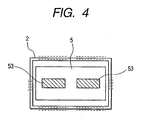
- FIG. 4 is a left side view of the fuel cell system in FIG. 1.
- FIG. 5 is a schematic diagram showing a system of the fuel cell system of the present invention.
- FIGS. 2A and 3A show the state of the inside of the fuel cell system as if it is seen from the outside of a transparent housing 2.
- the external dimensions of the fuel cell system of the present invention shown in FIG. 1 they are 30 mm in length (a) ⁇ 50 mm in width (b) ⁇ 10 mm height (c), and the fuel cell system has almost the same dimensions as those of a lithium ion battery usually used for a compact digital camera.
- FIG. 8 is a schematic perspective view showing a digital camera in which the fuel cell system of the present invention is mounted.
- a digital camera 91 which is one of the small electric device of the present invention is small and unified
- a small fuel cell system 92 has a shape of being easily built in the digital camera which is a portable device.
- a thin rectangular parallelepiped shape of a fuel cell system makes it easy to build it in small electric device in comparison with a thick rectangular parallelepiped shape or a cylindrical shape.
- the present invention maximizes a fuel tank capacity for obtaining a sufficient battery capacity in the volume of a small housing, a fuel cell area for obtaining a sufficient output, and a number of air vents for efficiently supplying an oxidizer to the fuel cell, and at the same time, optimizes the positional relation among the fuel tank unit, the fuel feed unit and the cell unit inside the housing.
- the fuel cell system of the present invention is a portable fuel cell system mounted in and used for small electric device such as a digital camera, a digital video camera, a small projector, a small printer and a notebook sized personal computer, comprising a cell unit 1 comprising four fuel cells 14, a fuel tank unit 3 for storing a fuel to be supplied to the cell unit 1, a fuel feed unit 4 for supplying the fuel of the fuel tank unit 3 to the cell unit 1, openings 7 for supplying an oxidizer gas to the cell unit 1, and a wiring unit 5 for collecting and temporarily storing the power generated by the cell unit 1, and supplying to the external the power which is always stabilized, in a thin housing 2 having a substantially rectangular parallelepiped shape, wherein the above-mentioned fuel tank unit 3, fuel feed unit 4, and cell unit 1 are located in this order in one direction between two opposite short side faces 83a and 83b of the housing 2.
- the fuel cell system of the present invention has openings 7, which are air vents for taking in the open air and provided in a top face 82, a bottom face 81, and long side faces 84a and 84b of the housing 2, so as to take in oxygen used for a reaction as an oxidizer gas from the open air.
- the openings 7 also perform actions of releasing generated water as steam and releasing the heat generated by a reaction to the outside.
- the wiring unit 5 is provided in one short side face 83b of the housing 2, and electrodes 53 for taking out electricity are provided in the wiring unit 5.
- the inside of the housing 2 is constituted by a cell unit 1 each including one or more fuel cells 14 comprising a fuel electrode 13, a polymer electrolyte membrane 12, an oxidizer electrode 11 and a catalyst (see FIG. 5), the fuel tank unit 3 for storing a fuel, the fuel feed unit 4 for decompressing the fuel from the fuel tank and leading it to a reactive electrode of each cell, and the wiring unit 5 for collecting a power generated by each fuel cell 14.
- a cell unit 1 each including one or more fuel cells 14 comprising a fuel electrode 13, a polymer electrolyte membrane 12, an oxidizer electrode 11 and a catalyst (see FIG. 5)
- the fuel tank unit 3 for storing a fuel
- the fuel feed unit 4 for decompressing the fuel from the fuel tank and leading it to a reactive electrode of each cell
- the wiring unit 5 for collecting a power generated by each fuel cell 14.
- FIG. 5 is a schematic diagram showing a system of the fuel cell system of the present invention shown in FIG. 1.
- the fuel contained in the fuel tank unit 3 is supplied to the fuel electrode 13 of the fuel cell 14 of the cell unit 1 through the fuel feed unit 4 from the fuel tank unit 3.
- Air is used for an oxidizer gas and the open air is supplied to the oxidizer electrode 11 of the fuel cell 14 through the openings 7 which are air vents.
- the cell unit 1 is constituted by one or more fuel cells 14, and the fuel cell 14 comprises the fuel electrode 13, the polymer electrolyte membrane 12, the oxidizer electrode 11 and a catalyst. This is constituted so that the power generated in each fuel cell 14 by the supply of the fuel from the fuel tank unit 3 and the oxidizer gas from the open air is temporarily stored in the wiring unit 5, and the generated power always stabilized is supplied to the external from the electrodes 53.
- FIGS. 6A and 6B are schematic diagrams showing the arrangement relationship among the cell unit, the fuel tank unit and the openings in the fuel cell system of the present invention.
- FIG. 6A shows the same arrangement as in FIG. 1, and the cell unit 1, the fuel feed unit 4 and the fuel tank unit 3 are located in series between the short side faces 83a and 83b of the housing 2 in one direction, and the fuel tank unit 3 exists in the side face of the fuel cell 14. Moreover, the top face 82 and bottom face 81 of the housing 2 which each having the openings 7 are located in the locations opposite to faces of the fuel cell.
- FIG. 6B is constituted by locating the openings 7 to the faces where the surface areas of the housing 2 of the fuel cell system become maximum, locating the fuel cells 14 of the cell unit 1 in the location facing the face having the openings 7, and locating the fuel tank unit 3 inside the cell unit 1.
- the fuel feed unit 4, the fuel tank unit 3, the fuel feed unit 4, and the cell unit 1 are located between the top face 82 and bottom face 81 of the housing 2.
- the fuel cells 14 are located at both sides of the fuel tank unit 3 (top face side and bottom face side of the housing), it is also sufficient that the fuel cells 14 are only on the top face side of the housing 2, or are only on the bottom face side of the housing 2.
- the system in FIG. 6A When a fuel cell system is thin, the system in FIG. 6A is effective so as to take a large fuel tank capacity. On the other hand, more efficiently, in order to take in an oxidizer from openings and to supply it to an oxidizer electrode, the system in FIG. 6B is effective.
- the fuel cell of the present invention is an electromotive force of 0.8 V and current density of 300 mA/cm 2 , and dimensions of a unit cell is 1.2 cm ⁇ 2 cm.
- An output of the entire battery is 4.6 W at 6.4 V and 720 mA by connecting eight sheets of these fuel cells in series.
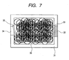
- FIG. 7 is a schematic diagram showing the outline of the fuel tank.
- the fuel cell system of the present invention uses hydrogen as fuel.
- the inside of a fuel tank 31 is filled with a carbon-based material 36 capable of occluding the hydrogen, such as a carbon nanotube, a graphite nanofiber or a carbon nanohorn.
- These carbon-based materials 36 can occlude about 10 % by weight of hydrogen at the pressure of 4 MPa. Since the internal pressure of the fuel tank after hydrogen occlusion becomes high pressure of about 4 MPa, it is desirable to use a material having a high strength such as stainless steel, a magnesium alloy, or titanium as the fuel tank 31.
- the thickness of a material is required to be about 2 mm or more in the case of stainless steel or about 1 mm or more in the case of titanium.
- the outer dimensions of the fuel tank is 2.5 cm ⁇ 3 cm ⁇ 1 cm. It is assumed that titanium is used for an outer wall and the tank has a thickness of 1 mm. At this time, the weight of the fuel tank becomes about 10 g, and the volume of the fuel tank becomes 5.2 cm 3 . These are about one thirds the weight and 1.5 times the volume in comparison with the case of using stainless steel for an outer wall of the fuel tank.
- the energy stored in the fuel tank is about 7.0 W ⁇ hr, which is about 2.5 times the conventional lithium ion battery.
- a fuel cell system with a mobile device integrally.
- it is also possible to replace only a fuel tank at the time of replacement of a fuel by producing the fuel tank detachably from a cell unit. It is also possible that a user replaces a whole fuel cell system and a person of repacking a fuel takes out only a fuel tank. It is also possible to replace only the battery portion other than a fuel tank against the exhaustion of a catalyst, etc. or the degradation of a polymer electrolyte membrane.
- a fuel release hole 34 is provided in the fuel tank 31, and when the fuel tank is made into the structure detachable from a fuel cell system, hydrogen is supplied to the cell unit 1 from the fuel release hole 34 by attaching the fuel tank to the fuel cell system. In that case, and a release valve 35 is attached to the fuel release hole 34 in order not to leak a fuel outside when the fuel tank is removed, the valve opens only when the fuel tank 31 is mounted in the fuel cell system. It is also possible that a fuel inlet 32 serves as the fuel release hole 34 in one opening.
- a housing having a substantially rectangular parallelepiped shape which is small and thin is used as the housing 2, which may partially have a transformation, a convexity, or a concavity in a rectangular parallelepiped.
- a thin housing with the height (c) of 2 to 100 mm is preferable.
- a fuel cell system of this embodiment according to the second invention of the present invention is formed by stacking at least one or more of two types of fuel cell(s) A and fuel cell(s) B by turns, wherein the fuel cell A has a fuel electrode on one face and an oxidizer electrode on another face, and on the contrary to the fuel cell A, the fuel cell B has an oxidizer electrode on one face and a fuel electrode on another face, wherein the cells are stacked by turns so that the fuel electrode of the cell A and the fuel electrode of the cell B face each other and the oxidizer electrode of the cell A and the oxidizer electrode of the cell B face each other, and wherein a common fuel flow path is provided between the fuel electrodes of the above-mentioned fuel cells A and B which face each other, and a common oxidizer flow path is provided between the oxidizer electrodes which face each other.
- a fuel cell also serves as a separator of a conventional battery by locating fuel cells in both sides of a fuel flow path
- a stacking system of the fuel cell system of the present invention does not require a separator. Owing to this system, since it is possible to enlarge the depth of a fuel flow path, for example, to make it two times the conventional, it is possible to supply a fuel to the cells very efficiently.
- a supporting member for the oxidizer flow path. Since a separator is not used for the fuel cell system of the present invention unlike a conventional stacking method, it is necessary to collect independently the electricity generated in each fuel cell. In the present invention, the electricity taken off from each electrode of fuel cells is collected in the wiring unit provided in the outside of the cell unit. When using this system, it is possible to prevent the spill of the fuel from wiring lines which was a problem of a three-dimensional wiring system.
- FIG. 1 is a perspective view showing an example of a fuel cell system of the present invention.
- FIG. 2A is a plan view of the fuel cell system in FIG. 1.
- FIG. 2B is a partially sectional plan view of the fuel cell system in FIG. 1.
- FIG. 9A is a front view of the fuel cell system in FIG. 1.
- FIG. 9B is a partially sectional front view of the fuel cell system in FIG. 1.
- FIG. 4 is a left side view of the fuel cell system in FIG. 1.
- FIG. 10 is an explanatory diagram showing the structure of a cell unit of the fuel cell system according to the present invention.
- FIG. 11 is a schematic diagram showing a system of the fuel cell system of the present invention.
- FIGS. 2A and 9A show the state of the inside of the housing as if seen from the outside of a transparent housing 2.
- FIG. 8 is a schematic diagram showing a digital camera in which the fuel cell system of the present invention is mounted. As shown in FIG. 8, since a digital camera 91 which is one of the small electric device of the present invention is small and unified, a small fuel cell system 92 has a shape of being easily built in the digital camera which is a portable device.
- each fuel cell is stacked so that the fuel electrodes face each other and the oxidizer electrodes face each other, and a common fuel flow path is provided between the fuel electrodes of the fuel cells which face each other and a common oxidizer flow path is provided between the oxidizer electrodes which face each other.
- the fuel cell system of the present invention comprises a cell unit 1 comprising two fuel cells A and two fuel cells B, a fuel tank unit 3 for storing a fuel to be supplied to the cell unit 1, a fuel feed unit 4 for supplying the fuel of the fuel tank unit 3 to the cell unit 1, air vents 7 for supplying an oxidizer gas to the cell unit 1, and a wiring unit 5 for collecting and temporarily storing the power generated by the cell unit 1, and supplying to the external the power which is always stabilized.
- the fuel cell system of the present invention has the air vents 7 for taking in the open air, in a top face 82, a bottom face 81, and long side faces 84a and 84b of the housing 2 so as to take in oxygen used for a reaction as an oxidizer gas from the open air. Moreover, the air vents 7 also perform actions of releasing generated water as steam and releasing the heat, generated by a reaction, to the outside.
- the wiring unit 5 is provided on one short side face 83b of the housing 2, and electrodes 53 for taking off electricity are provided in the wiring unit 5.
- an inside of the housing 2 is constituted by the cell unit 1 each comprising one or more fuel cells A and B (14A, 14B) comprising a fuel electrode 13, a polymer electrolyte membrane 12, an oxidizer electrode 11 and a catalyst (see FIG. 11); a fuel tank unit 3 for storing a fuel; a fuel feed unit 4 for decompressing the fuel from the fuel tank and leading it to a reactive electrode of each cell; and a wiring unit 5 for collecting the power generated by respective fuel cells 14A and 14B.
- the cell unit 1 each comprising one or more fuel cells A and B (14A, 14B) comprising a fuel electrode 13, a polymer electrolyte membrane 12, an oxidizer electrode 11 and a catalyst (see FIG. 11); a fuel tank unit 3 for storing a fuel; a fuel feed unit 4 for decompressing the fuel from the fuel tank and leading it to a reactive electrode of each cell; and a wiring unit 5 for collecting the power generated by respective fuel cells 14A and 14B.
- the fuel cell system of the present invention is provided by stacking two types of fuel cells A (14A), and the fuel cells B (14B) by turns, the fuel cell A having a fuel electrode 13a on the lower face and having the oxidizer electrode 11a on the upper face, and the fuel cell B having the oxidizer electrode 11b on the lower face and having the fuel electrode 13b on the upper face reversely to the fuel cell A, so that the fuel electrode 13a of the fuel cell A and the fuel electrode 13b of the fuel cell B face each other, on the other hand, the oxidizer electrode 11a of the fuel cell A and the oxidizer electrode 11b of the fuel cell B face each other, wherein a fuel flow path 43 common between the fuel electrode 13a and fuel electrode 13b of the above-mentioned fuel cells A and B which face each other is provided, and an oxidizer flow path 44 common between the oxidizer electrode 11a and oxidizer electrode 11b which face each other is provided.
- the above-mentioned fuel cell A and fuel cell B may have the same structure, and that the fuel cells are stacked by turns and provided so that the fuel electrodes face each other and the oxidizer electrodes face each other by reversing one kind of the fuel cells. That is, when reversing the fuel cell A, the fuel electrode and oxidizer electrode of the fuel cell A become the structure of the fuel electrode and oxidizer electrode of the fuel cell B.
- the fuel cell serves also as a separator of a conventional fuel cell system by providing the fuel cells on both of the upper and lower sides of the fuel flow path 43 when generating electricity in a plurality of fuel cells, a separator is unnecessary.
- a gaseous fuel such as hydrogen
- a liquid fuel such as chemical hydride, methanol or dimethyl ether
- an oxidizer, oxygen, air or the like is used as the fuel.
- supporting members 46 are provided in both sides of the oxidizer flow path 44. Since the supporting members suppress the transformation of the cells, it is possible to prevent the breakage of the cells to prevent the leak of the fuel, and, it is also possible to prevent the contact of the cells.
- porous structures in the supporting member.
- porous material for example, porous carbon, porous silicon, etc. are preferable.
- FIG. 11 is a schematic diagram showing a system of the fuel cell system of the present invention shown in FIG. 1.
- the fuel contained in the fuel tank unit 3 is supplied to the fuel electrodes 13 of the fuel cells A and B of the cell unit 1 through the fuel feed unit 4 from the fuel tank unit 3.
- Air is used as an oxidizer gas and the open air is supplied to the oxidizer electrodes 11 of the fuel cells A and B through the air vents 7 which are air vents.
- the cell unit 1 is constituted by one or more fuel cells A and B, and the fuel cells each comprise the fuel electrode 13, a polymer electrolyte membrane 12, the oxidizer electrode 11 and a catalyst.
- the fuel cell system of the present invention takes off electric power without spoiling the fuel-sealing performance of fuel by collecting the electricity taken off from each electrode with serial wiring 51 of the wiring unit 5 on the opposite side of a fuel chamber.
- by locating the wiring unit 5 in a vertical location to a fuel cell it is possible to shorten a wiring distance and to simplify the wiring.
- it is possible to further simplify the wiring by locating electrodes for supplying an electric power to a small electric device from a fuel cell system adjacent to the wiring unit.
- the energy stored in the fuel tank is about 7.0 W ⁇ hr, which is about 2.5 times the conventional lithium ion battery.
- an electromotive force is 0.8 V
- current density is 300 mA/cm 2
- dimensions of a unit cell is 1.2 cm ⁇ 2 cm.
- An output of the entire battery is 4.6 W at 6.4 V and 720 mA by connecting eight sheets of these fuel cells in series.
- the third embodiment is characterized by the structure for taking off electric power from each fuel cell and the structure for collecting the taken-out electric power in a stacking system of so-called homopolar opposed type fuel cells where fuel electrodes face each other and oxidizer electrodes of adjacent fuel cells face each other, respectively.
- FIG. 13A is a perspective view for explaining a form of taking off electric power by collector members provided between fuel cells.
- FIG. 13B is a perspective view of the state that the fuel cells and collector members are stacked.
- Reference numeral 110 denotes a collector member
- 111 denotes a power takeoff part (electric power output port) of the collector member 110
- 112 denotes an air vent of the collector member 110
- 147a and 147b denote insulating members
- 147a denotes a supporting member of an oxidizer electrode chamber
- 147b denotes a fuel electrode chamber partition wall.
- the collector member 110 is provided in contact with the fuel cell 14, and collects the electric power generated in the fuel cells.
- the electric power of the fuel cells is taken off from the electrode takeoff part 111 of the collecting electrode 110.
- the supporting member 147a of the oxidizer electrode chamber and the fuel electrode chamber partition wall 147b are provided between a fuel cell and another fuel cell (corresponding to the oxidizer electrode chamber and fuel electrode chamber, respectively) so as not to contact adjacent fuel cells mutually and contact adjacent collector member 110 mutually.
- FIG. 14A is a plan view of the collector member 110.
- the collector member 110 is made of a material which has electroconductivity, and is installed on each side of the oxidizer electrode and fuel electrode which is not in contact with a polymer electrolyte membrane.
- Metal a carbon material such as graphite can be used as a material which has electroconductivity.
- the material is a material which is not polluted with fuel or pollutes neither a catalyst nor an electrolyte membrane.
- stainless steel or graphite can be used, for example.
- the collector member has air permeability so as not to interfere the supply of a fuel and an oxidizer.
- a porous member may be used or the air vent 112 may be provided.
- the collector member has the power takeoff part 111, and the generated electricity can be collect by performing wiring from an electricity takeoff part. By performing the wiring suitably, it is possible to connect a plurality of fuel cells in parallel or in series.
- a fourth embodiment is an embodiment of forming a stack of a collector member, fuel cells, supporting members as oxidizer electrodes, and fuel electrode chamber partition walls by using the collector member having a power takeoff part shifted from the center.
- FIG. 14B is a plan view of the collector member having the power takeoff part shifted from the center.
- the stack becomes the state as shown in FIG. 15.
- FIG. 15 is a perspective view of the state of stacking fuel cells and collector members in the case of parallel connection of the plurality of fuel cells by using the collector members each having the power takeoff part shifted from the center shown in FIG. 14B.
- the collector members 110 with the same polarity are stacked so that the same electrode takeoff parts 111 are arranged on the same side.
- Negative electrodes are located on the right-hand side, and positive electrodes are located on the left-hand side. Since electrodes with the same polarity are arranged on the same side, the polarity of the electrodes is distinguished easily.
- FIG. 16A is a diagram for explaining the state that a stack 113 of fuel cells and collector members, as shown in FIG. 15, is connected to a circuit board.
- a wiring member 120 is connected to the electrode takeoff parts 111 of the stack 113 so as to become vertical to the cells 14.
- FIG. 16B is a diagram showing the connection structure of the collector members and circuit board.
- Reference numeral 122 denotes a wiring provided on the circuit board 120
- 121 denotes an entry of a collector member provided in the circuit board 120.
- the electrode takeoff parts 111 are inserted into the entries 121 of the circuit board 120, and a plurality of collector members are mutually connected electrically by the wiring 122.
- FIG. 16C is a front view showing the circuit board. It is possible to connect a plurality of fuel cells in parallel by electrically connecting the entries 121 as shown in the diagram. The collected electric power is led to the positive electrode 53 and negative electrode 53. Although an electromotive force of each fuel cell is small at about 0.8 V, it is possible to transform the voltage by using a DC-DC converter, etc. to supply electric power in the optimal voltage for an electric device.
- a fifth embodiment is a form of connecting respective fuel cells in series.
- FIG. 17 is a perspective view of the state of stacking the fuel cells and collector members in the case of serial connection of the plurality of fuel cells.
- the collector members 110 are stacked so that their face and back may be changed by turns as shown in FIG. 17.
- FIG. 18A is a diagram showing the connection structure of the collector members and the circuit board.
- FIG. 18B is a front view showing the circuit board.
- Respective fuel cells can be electrically connected in series by connecting the stack of the fuel cells and collector members to the circuit board 121 having a wiring pattern as shown in FIG. 18B.
- a collector member when a collector member has a sufficient strength, it has a function of preventing a polymer electrolyte membrane from breaking or peeling from a joint which is caused by the pressure change of a fuel tank, etc.
- the sixth embodiment is an embodiment for obtaining a stack of fuel cells, which is compact and has a high strength, without using a collector member.
- FIG. 19A is a perspective view of two fuel cells and supporting members for supporting them.
- FIG. 19B is a plan view of FIG. 19A.
- FIG. 19C is a sectional view taken in the line 19C-19C of FIG. 19B.
- Reference numeral 146 denotes a supporting member
- 147a denotes a supporting member provided in the end of an oxidizer electrode chamber
- 147b denotes a fuel electrode chamber partition wall.
- the fuel electrode chamber partition wall 147b (or supporting member 147b) is sandwiched by two fuel cells 14, and other supporting members 146 are located near the center between two fuel cells 14 in a scattered manner to support the fuel cells 14.
- the supporting members 146 can increase the strength of the stack of fuel cells. Since as shown in FIGS. 19A to 19C, a plurality of block-like supporting members 146 are located in a spattered manner, the flow of a fuel (or an oxidizer) between two fuel cells 14 is not disturbed.
- the stack of fuel cells of the sixth embodiment does not have a collector member, it becomes thin correspondingly. Moreover, since the supporting members 146 are pressing the surfaces of the fuel cells 14, the breaking and peeling of a polymer electrolyte membrane caused by the pressure of the fuel, etc. is prevented.
- the partition wall 147b in the fuel electrode chamber it is preferable to have hermeticity so that fuel may not leak outside.
- the supporting member 146a located in the end of the oxidizer electrode chamber it is preferable to have air permeability when adopting the open air as an oxidizer.
- FIGS. 20A to 24B The modified examples of the stack of fuel cells of the sixth embodiment shown in FIGS. 19A to 19C are shown in FIGS. 20A to 24B.
- FIG. 20A is a plan view of two fuel cells and porous supporting members supporting them.
- FIG. 20B is a sectional view taken in the line 20B-20B of FIG. 20A.
- a porous material is used as the supporting member 146. For this reason, the flow of a fuel (or an oxidizer) is not disturbed.
- FIG. 21A is a plan view of two fuel cells and porous supporting members supporting them.
- FIG. 21B is a sectional view taken in the line 21B-21B of FIG. 21A.
- the supporting member 146 is larger than the supporting member 146 shown in FIG. 19A, the flow of a fuel (or an oxidizer) is not disturbed since a porous material is used as the material thereof.
- FIG. 22A is a plan view of two fuel cells and the supporting members which support them and have air vents.
- FIG. 22B is a sectional view taken in the line 22B-22B of FIG. 22A.
- the supporting member 146 has air vents 150. Since a fuel (or an oxidizer) can flow through the air vents 150, the flow of the fuel (or oxidizer) is not disturbed.
- FIG. 23A is a plan view of two fuel cells and the supporting members which support them and have air vents.
- FIG. 23B is a sectional view taken in line the 23B-23B of FIG. 23A.
- the supporting member 146 is larger than the supporting member 146 shown in FIG. 19A, the flow of a fuel (or an oxidizer) is not disturbed since it has the air vents 150.
- FIG. 24A is a plan view of two fuel cells and spherical supporting members supporting them.
- FIG. 24B is a sectional view taken in the line 24B-24B of FIG. 24A.
- the shape of the supporting member 146 may be sphericity.
- the seventh embodiment is an embodiment that supporting members each located at the end of an oxidizer electrode chamber between fuel cells, and a fuel electrode chamber partition wall play the role for collecting the electric power generated in the fuel cells instead of providing a member for collecting electricity like the collector member in the third embodiment.
- FIG. 26 is a diagram for explaining the positional relation among the fuel cells 14, a circuit board 120a, and supporting members 147a, each located at the end of an oxidizer electrode chamber, and a fuel electrode chamber partition wall 147b in the case of parallel connection of two fuel cells.
- Reference numeral 131 denotes an entry which is provided in a wiring member 120a and into which the supporting member 147a or partition wall 147b is inserted
- 143 denotes a fuel electrode chamber
- 144 denotes an oxidizer electrode chamber.
- the partition wall 147b of the fuel electrode chamber and the supporting member 146 are inserted between two fuel cells 14.
- the supporting member 147a located at the end of an oxidizer electrode chamber and another supporting member 146 are provided in another face of a fuel cell 14.
- Each of the ends of two supporting members 147a and one partition wall 147b protrudes from fuel cells (protrudes from a space where two fuel cells surround), and is inserted into an entry 131 of the circuit board 120a.
- conductive materials are used as the supporting member 147a of an oxidizer electrode chamber, and the partition wall 147b of a fuel electrode chamber.
- the electric power generated in the fuel cells 14 is taken off to the wiring member 120a through these supporting members 147a and partition wall 147b.
- the supporting members 147a located at the ends of the oxidizer electrode chambers and the partition wall 147b of the fuel electrode chamber can play the role of collecting the electric power generated in the fuel cells while preventing the contact of adjacent fuel cells.
- insulating films may be provided therebetween.
- FIG. 27 is a diagram for explaining the positional relation between fuel cells and a conductive fuel electrode chamber partition wall which has a wiring function to a circuit board (in the case of parallel connection).
- the partition wall 147b of a fuel electrode chamber is provided between two fuel cells 14.
- the end of the partition wall 147b protrudes from a space where two fuel cells surround.
- the fuel electrodes of two fuel cells 14 face each other, and the fuel electrode chamber 143 is formed in a space between the cells.
- a fuel flows to the inside of this fuel electrode chamber 143, and contributes to electric power generation through the oxidizer electrode of the fuel cells 14.
- the electric power generated in the fuel cells 14 is taken off through the partition wall 147b in contact with the fuel electrode of the fuel cells 14.
- FIG. 28A is a perspective view of the fuel electrode chamber partition wall 147b (the supporting member 147a located at the end of the oxidizer electrode chamber).
- FIG. 28B is a plan view of FIG. 28A.
- a shape of the partition wall is U-shaped, and a portion exactly corresponding to a portion of the bottom of the U-shape protrudes from a space between the fuel cells as shown in FIGS. 26 and 27.
- a region surrounded by two arms of the U-shape is a region used as the fuel electrode chamber 143 (oxidizer electrode 144) of the stack of the fuel cells.
- FIG. 29 is a diagram for explaining the circuit board 121a and its wiring pattern for the parallel connection of two fuel cells.
- the supporting members 147a located at the ends of two oxidizer electrode chambers and the partition wall 147b of a fuel electrode chamber are inserted into the entries 131, respectively.
- the top and bottom entries 131 are electrically connected by the wiring 22.
- FIG. 26 it is possible to electrically connect two fuel cells 14 in parallel by connecting the stack of fuel cells to the circuit board 121a.
- the eighth embodiment differs from the seventh embodiment in the point of using a partition wall having a joint with a circuit board which is shifted from the center.
- FIG. 30 is a plan view of a fuel electrode chamber partition wall 147b (a supporting member 147a located at the end of an oxidizer electrode chamber) having a joint with a circuit board which is shifted from the center.
- a shape of this partition wall is a shape as just reversing the alphabet "y”. It is possible to distribute the locations of joints of positive electrodes and joints of negative electrodes to the right and left, respectively, by reversing the orientation of supporting members 147a of two oxidizer electrodes and one fuel electrode partition wall 146b.
- FIG. 31 is a diagram for explaining the circuit board 120a and its wiring pattern in the case of using the partition wall in FIG. 30 (this wiring pattern is a pattern of connecting two fuel cells in parallel).
- Two right-hand entries are electrically connected by the wiring 122. Since two supporting members 147a inserted into these two entries respectively have the same polarity, it is possible to connect two fuel cells 14 in parallel.
- the supporting members 147a as a positive electrode are inserted into two right-hand entries 131, and the partition wall 147b as a negative electrode is inserted into the left-hand entry 131. Since partition walls having the same polarity are arranged on the same side, polarity distinction is easy, and a pattern of the wiring 122 is also simple.
- an electromotive force of each fuel cell is small at about 0.8 V, it is possible, by transforming it by using a DC-DC converter, etc., to output the optimal voltage for an electric device outside the fuel cell system.
- the eighth embodiment is the case where the number of fuel cells is two, it is possible to apply a similar structure also to the case that the number of cells is four, that is, the case is shown in FIGS. 30 and 31.
- FIG. 32 is a diagram for explaining the positional relation among fuel cells, a circuit board, supporting members located at the ends of oxidizer electrode chambers, and fuel electrode chamber partition walls in the case of parallel connection of four fuel cells.
- Four fuel cells 14, three supporting members 147a, and partition walls 147b are located by turns.
- FIG. 33 is a diagram for explaining a circuit board and its wiring pattern for parallel connection of four fuel cells.
- U-shaped members shown in FIG. 28B are used as supporting members 147a and partition walls 147b, locations of entries 131 of the circuit board 120b corresponding to the ends of three supporting members 147a, and the ends (portions of bottoms of U-shapes) of two partition walls 147b become one column as shown in FIG. 34.
- FIG. 34 is a diagram for explaining another circuit board for parallel connection of four fuel cells, and its wiring pattern.
- the first, third, and fifth steps of entries 131 from the top are electrically connected by the wiring 122, and, on the other hand, the second, and fourth steps of entries 131 from the top are electrically connected. Owing to such structure, it is possible to easily connect five fuel cells 14 in parallel.
- the ninth embodiment differs from the eighth embodiment in the point that fuel cells are not connected in parallel, but they are connected in series.
- FIG. 35 is a diagram for explaining the positional relation among fuel cells, an insulating fuel electrode partition wall, and conductive members.
- FIG. 36 is a diagram for explaining the positional relation among fuel cells, a circuit board and fuel electrode chamber partition walls in the case of serial connection of the two fuel cells.
- the partition wall 147b in order to insulate two fuel cells 14, which face each other with sandwiching the fuel electrode chamber partition wall 147b between the cells, the partition wall 147b has insulating property.
- a conductive member 160 is provided between the fuel cell 14 and a partition wall 147b. Electric power is taken off through this conductive member 160.
- an insulating material is used also as a supporting member 147a located at the end of an oxidizer electrode chamber.
- FIG. 37 is a diagram for explaining a circuit board and its wiring pattern in the case of serial connection of two fuel cells.
- Reference numeral 132 denotes an entry of a conductive member.
- a stack of cells is constituted by using the insulating partition walls 147b and supporting members 147a which are shown in FIG. 36 and these are joined with the circuit board 120d, it becomes the state as shown in FIG. 37. Since an upper fuel cell 14 and a lower fuel cell 14 are insulated, electric power is taken off from a fuel electrode and an oxidizer electrode of each fuel cell 14 through conductive members 160 which contact to these electrode, respectively. Since fuel electrodes of respective fuel cells are insulated from each other, it is possible to connect the positive electrode of one fuel cell 14, and the negative electrode of another fuel cell with the wiring 122. Owing to this, it is possible to connect two fuel cells 14 in series.
- FIG. 38 is a diagram for explaining the positional relation among fuel cells, a circuit board 120e, supporting members 147a and fuel electrode chamber partition walls 146a in the case of serial connection of the four fuel cells.
- Four fuel cells 14, three supporting members 147a, and two partition walls 147b are stacked by turns.
- a conductive member 160 is provided between each fuel cell 14 and a supporting member 147a or a partition wall 147b. The supporting members and partition walls are inserted into the entries 131 of the circuit board 120e, respectively.
- FIG. 39 is a diagram for explaining a circuit board and its wiring pattern in the case of serial connection of four fuel cells.
- the entries 131 and conductive member entries 132 are provided. Since electrodes of adjacent fuel cells 14 facing each other are insulated mutually, it is possible to connect five fuel cells 14 in series as shown in FIG. 39 by connecting the positive electrode of one fuel cell to the negative electrode of another fuel cell adjacent to this one fuel cell.
- FIG. 40 is a diagram for explaining the positional relation among fuel cells, electroconductive support members located at the ends of oxidizer electrode chambers, fuel electrode partition walls insulating members and conductive members.
- Reference numeral 161 denotes an insulating member. The insulating member 161 is provided between a conductive supporting member 147a or a conductive partition wall 147b, and a fuel cell 14, and the conductive member 161 is provided between an insulating member 161 and a fuel cell 14.
- the insulating member 161 can be formed on the surfaces of a supporting member 147a and a partition wall 147b by a method such as an applying or coating method.
- the conductive member can be formed by applying, coating, evaporation, etc. on the supporting member and an insulating member 160 of the partition wall.
- the tenth embodiment is an embodiment of preventing two fuel cells, which faces each other in the state that oxidizer electrodes counter each other, from becoming conductive with the water generated in the oxidizer electrode.
- FIG. 41 is a structural diagram of the cell unit of the fuel cell system which has a water shutoff member between two fuel cells.
- Reference numeral 148 denotes a member which shuts off the water generated in the oxidizer electrode.
- a plurality of supporting members 146 are provided between the cells which counter each other with facing the oxidizer electrodes of the cells each other and sandwiching a supporting member 147a located at the end of the oxidizer electrode, and water cutoff means is provided among the plurality of supporting members 146. It is possible to prevent the movement of the water generated in an oxidizer electrode of one cell to an opposite cell by the water cutoff means.
- a gas liquid separation film, etc. is suitable in the viewpoint of not disturbing the supply of air.
- a method of using a hydrophobic member as a supporting member 146 can be employed as another method for shutting off water.
- a method of using a member made of a hydrophobic porous material as the supporting member 146, in which the surface areas of a porous material in the center section of the supporting member are large, can be employed.
- methods of increasing the surface areas a method of increasing the density of holes without changing dimensions of the holes and a method of making dimensions of holes small to increase their number can be employed.
- the arrangement relation of respective units constituting a fuel cell system is specified, it is possible to provide a large-capacity and high-output fuel cell system which is mountable in a small and portable electric device, and is miniaturized. Moreover, it is possible to provide a fuel cell system that only a fuel tank cartridge can be exchanged.
- the second invention of the present invention it is possible to provide a fuel cell system that a fuel is efficiently supplied to fuel cells and a plurality of fuel cells are made compact by broadening the fuel flow paths by stacking respective fuel cells so that the fuel electrodes of the cells face each other and the oxidizer electrodes face each other respectively, and providing a common fuel flow path and a common oxidizer flow path between fuel cells.
- the fuel cell system of the present invention it is possible to provide a portable and small electric device such as a digital camera, a digital video camera, a small projector, a small printer, a notebook sized personal computer, or the like.
Landscapes
- Life Sciences & Earth Sciences (AREA)
- Engineering & Computer Science (AREA)
- Manufacturing & Machinery (AREA)
- Sustainable Development (AREA)
- Sustainable Energy (AREA)
- Chemical & Material Sciences (AREA)
- Chemical Kinetics & Catalysis (AREA)
- Electrochemistry (AREA)
- General Chemical & Material Sciences (AREA)
- Fuel Cell (AREA)
Applications Claiming Priority (5)
| Application Number | Priority Date | Filing Date | Title |
|---|---|---|---|
| JP2001374175 | 2001-12-07 | ||
| JP2001374174 | 2001-12-07 | ||
| JP2001374175 | 2001-12-07 | ||
| JP2001374174 | 2001-12-07 | ||
| PCT/JP2002/006513 WO2003049223A1 (fr) | 2001-12-07 | 2002-06-27 | Pile a combustible et dispositif electrique |
Publications (1)
| Publication Number | Publication Date |
|---|---|
| EP1471590A1 true EP1471590A1 (en) | 2004-10-27 |
Family
ID=26624934
Family Applications (1)
| Application Number | Title | Priority Date | Filing Date |
|---|---|---|---|
| EP02738829A Withdrawn EP1471590A1 (en) | 2001-12-07 | 2002-06-27 | Fuel battery and electric device |
Country Status (8)
| Country | Link |
|---|---|
| US (2) | US7615301B2 (ja) |
| EP (1) | EP1471590A1 (ja) |
| JP (1) | JP4994571B2 (ja) |
| KR (1) | KR100663170B1 (ja) |
| CN (1) | CN100490242C (ja) |
| AU (1) | AU2002313280A1 (ja) |
| CA (1) | CA2469473A1 (ja) |
| WO (1) | WO2003049223A1 (ja) |
Cited By (3)
| Publication number | Priority date | Publication date | Assignee | Title |
|---|---|---|---|---|
| WO2007060511A2 (en) * | 2005-11-24 | 2007-05-31 | Toyota Jidosha Kabushiki Kaisha | Fuel cell |
| WO2008000216A1 (de) * | 2006-06-29 | 2008-01-03 | Enerday Gmbh | Reformer für ein brennstoff zellensystem |
| EP1939964A1 (fr) * | 2006-12-27 | 2008-07-02 | St Microelectronics S.A. | Boîtier pour pile à combustible miniature |
Families Citing this family (32)
| Publication number | Priority date | Publication date | Assignee | Title |
|---|---|---|---|---|
| KR100663170B1 (ko) * | 2001-12-07 | 2007-01-02 | 캐논 가부시끼가이샤 | 연료전지 및 전기기기 |
| TW200405962A (en) * | 2002-10-02 | 2004-04-16 | Hitachi Ltd | Electronic device using fuel cells |
| JP4502604B2 (ja) * | 2003-06-27 | 2010-07-14 | 京セラ株式会社 | 電子機器 |
| JP4329425B2 (ja) | 2003-06-23 | 2009-09-09 | 株式会社ニコン | 電子機器およびカメラ |
| JP4004489B2 (ja) * | 2003-09-12 | 2007-11-07 | 三洋電機株式会社 | 燃料電池システム |
| JP2005108812A (ja) * | 2003-09-12 | 2005-04-21 | Sanyo Electric Co Ltd | 燃料タンク |
| JP4532924B2 (ja) * | 2003-09-19 | 2010-08-25 | 富士フイルム株式会社 | 携帯機器 |
| US20050227136A1 (en) * | 2004-03-15 | 2005-10-13 | Hiroshi Kikuchi | Fuel cell, electronic apparatus and camera |
| JP4532953B2 (ja) * | 2004-03-25 | 2010-08-25 | キヤノン株式会社 | 燃料供給装置および燃料電池 |
| JP2005327679A (ja) * | 2004-05-17 | 2005-11-24 | Canon Inc | 燃料電池の接続構造体および接続方法 |
| US7474075B2 (en) * | 2004-07-21 | 2009-01-06 | Angstrom Power Incorporated | Devices powered by conformable fuel cells |
| US8410747B2 (en) | 2004-07-21 | 2013-04-02 | Societe Bic | Flexible fuel cell structures having external support |
| JP4690701B2 (ja) * | 2004-11-10 | 2011-06-01 | 株式会社日立製作所 | 燃料電池モジュール |
| JP2006202511A (ja) * | 2005-01-18 | 2006-08-03 | Toagosei Co Ltd | 燃料電池 |
| JP4871515B2 (ja) * | 2005-02-17 | 2012-02-08 | キヤノン株式会社 | 電子機器 |
| JP2006332025A (ja) * | 2005-04-28 | 2006-12-07 | Hitachi Ltd | 燃料電池ユニットおよび電子機器 |
| JP2007103223A (ja) * | 2005-10-06 | 2007-04-19 | Toyota Motor Corp | 燃料電池およびその製造方法 |
| KR20070073340A (ko) | 2006-01-04 | 2007-07-10 | 삼성에스디아이 주식회사 | 하우징을 구비한 평판형 연료전지 어셈블리 |
| JP5479737B2 (ja) * | 2006-01-09 | 2014-04-23 | ソシエテ ビック | 携帯用燃料電池システムおよびそのための方法 |
| CN100511809C (zh) * | 2006-03-24 | 2009-07-08 | 中国科学技术大学 | 环形导体框架支撑的平板式固体氧化物燃料电池堆构件 |
| KR100729071B1 (ko) * | 2006-05-19 | 2007-06-14 | 삼성에스디아이 주식회사 | 연료공급장치 하우징 및 이를 이용하는 주변장치 모듈 |
| US20080090109A1 (en) * | 2006-08-10 | 2008-04-17 | Angstrom Power Inc. | Portable fuel cell power source and methods related thereto |
| ES2331764B1 (es) * | 2006-11-23 | 2010-10-22 | Celaya Emparanza Y Galdos, S.A. (Cegasa) | Pila de consumo que comprende una pila de combustible. |
| KR100868652B1 (ko) * | 2007-04-25 | 2008-11-12 | 지에스퓨얼셀 주식회사 | 연료전지 스택 |
| TW200933965A (en) * | 2008-01-31 | 2009-08-01 | Nan Ya Printed Circuit Board | Fuel-cell structure |
| KR100981993B1 (ko) | 2008-06-30 | 2010-09-13 | 삼성전기주식회사 | 전력공급장치 및 이를 구비한 휴대용 전자기기 |
| KR101109314B1 (ko) * | 2009-07-28 | 2012-01-31 | 삼성전기주식회사 | 연료전지 발전시스템을 구비한 휴대용 전자기기 |
| US20150303503A1 (en) * | 2012-12-04 | 2015-10-22 | Intelligent Energy Limited | Computing device |
| JP5904514B1 (ja) * | 2014-10-28 | 2016-04-13 | インターナショナル・ビジネス・マシーンズ・コーポレーションInternational Business Machines Corporation | 仮想マシンのスナップショットに対して更新を自動的に適用する方法、並びに、そのコンピュータ・システム及びコンピュータ・システム用プログラム |
| US10527928B2 (en) | 2016-12-20 | 2020-01-07 | Taiwan Semiconductor Manufacturing Co., Ltd. | Optical proximity correction methodology using pattern classification for target placement |
| CN114148208B (zh) * | 2021-11-23 | 2024-05-03 | 泉州湖南大学工业设计与机器智能创新研究院 | 一种电动汽车的电池容量调节方法及装置 |
| WO2023225464A2 (en) * | 2022-05-16 | 2023-11-23 | Prometheus Energy Group, Llc | Apparatus and method for a hydrogen powered generator |
Family Cites Families (18)
| Publication number | Priority date | Publication date | Assignee | Title |
|---|---|---|---|---|
| US3554803A (en) * | 1967-08-24 | 1971-01-12 | Studebaker Corp | Fuel cell designed for efficient stacking |
| JPS5240419B2 (ja) | 1972-01-19 | 1977-10-12 | ||
| JPS62226586A (ja) | 1986-03-27 | 1987-10-05 | Shin Kobe Electric Mach Co Ltd | 燃料電池 |
| JPH06310166A (ja) * | 1993-04-28 | 1994-11-04 | Sanyo Electric Co Ltd | 可搬式燃料電池電源 |
| JPH08131382A (ja) * | 1994-11-04 | 1996-05-28 | Matsushita Electric Ind Co Ltd | 電気掃除機 |
| EP0788172B1 (en) * | 1996-02-05 | 2001-12-05 | Matsushita Electric Industrial Co., Ltd. | Fuel cell for mounting on equipment |
| JP4028603B2 (ja) | 1996-02-05 | 2007-12-26 | 松下電器産業株式会社 | 機器搭載用燃料電池装置 |
| JP4296625B2 (ja) * | 1999-03-15 | 2009-07-15 | ソニー株式会社 | 発電デバイス |
| DE19921816C1 (de) * | 1999-05-11 | 2000-10-26 | Andre Peine | Brennstoffzellen-System und Brennstoffzelle für derartiges System |
| JP3668069B2 (ja) * | 1999-09-21 | 2005-07-06 | 株式会社東芝 | 燃料電池用液体燃料収容容器および燃料電池 |
| JP2001093561A (ja) | 1999-09-28 | 2001-04-06 | Toshiba Corp | 燃料電池 |
| EP1168451A3 (en) * | 2000-06-27 | 2005-11-09 | Canon Kabushiki Kaisha | Semiconductor device, and radiation detection device and radiation detection system having same |
| JP2002246582A (ja) * | 2000-10-26 | 2002-08-30 | Canon Inc | 放射線検出装置、その製造方法及びシステム |
| JP4887558B2 (ja) * | 2000-11-07 | 2012-02-29 | ソニー株式会社 | 燃料電池の使用方法 |
| FR2818808B1 (fr) * | 2000-12-22 | 2006-07-14 | Commissariat Energie Atomique | Pile a combustible pour l'alimentation d'appareils electroniques, notamment portables |
| JP2002198072A (ja) | 2000-12-26 | 2002-07-12 | Mitsubishi Electric Corp | 固体高分子型燃料電池 |
| US6794682B2 (en) * | 2001-04-04 | 2004-09-21 | Canon Kabushiki Kaisha | Semiconductor device, method for manufacturing the same, and radiation detector |
| KR100663170B1 (ko) * | 2001-12-07 | 2007-01-02 | 캐논 가부시끼가이샤 | 연료전지 및 전기기기 |
-
2002
- 2002-06-27 KR KR1020047008742A patent/KR100663170B1/ko not_active IP Right Cessation
- 2002-06-27 AU AU2002313280A patent/AU2002313280A1/en not_active Abandoned
- 2002-06-27 CA CA002469473A patent/CA2469473A1/en not_active Abandoned
- 2002-06-27 EP EP02738829A patent/EP1471590A1/en not_active Withdrawn
- 2002-06-27 JP JP2003550307A patent/JP4994571B2/ja not_active Expired - Fee Related
- 2002-06-27 US US10/497,700 patent/US7615301B2/en not_active Expired - Fee Related
- 2002-06-27 CN CNB02826861XA patent/CN100490242C/zh not_active Expired - Fee Related
- 2002-06-27 WO PCT/JP2002/006513 patent/WO2003049223A1/ja active Application Filing
-
2009
- 2009-10-01 US US12/571,876 patent/US8580458B2/en not_active Expired - Fee Related
Non-Patent Citations (1)
| Title |
|---|
| See references of WO03049223A1 * |
Cited By (9)
| Publication number | Priority date | Publication date | Assignee | Title |
|---|---|---|---|---|
| WO2007060511A2 (en) * | 2005-11-24 | 2007-05-31 | Toyota Jidosha Kabushiki Kaisha | Fuel cell |
| WO2007060511A3 (en) * | 2005-11-24 | 2007-09-20 | Toyota Motor Co Ltd | Fuel cell |
| CN101313430B (zh) * | 2005-11-24 | 2011-06-29 | 丰田自动车株式会社 | 燃料电池 |
| US7972737B2 (en) | 2005-11-24 | 2011-07-05 | Toyota Jidosha Kabushiki Kaisha | Fuel cell |
| WO2008000216A1 (de) * | 2006-06-29 | 2008-01-03 | Enerday Gmbh | Reformer für ein brennstoff zellensystem |
| AU2007264245B2 (en) * | 2006-06-29 | 2010-03-25 | Enerday Gmbh | Reformer for a fuel cell system |
| KR101009426B1 (ko) * | 2006-06-29 | 2011-01-19 | 에너다이 게엠베하 | 연료 전지 시스템용 개질기 |
| EP1939964A1 (fr) * | 2006-12-27 | 2008-07-02 | St Microelectronics S.A. | Boîtier pour pile à combustible miniature |
| FR2911009A1 (fr) * | 2006-12-27 | 2008-07-04 | St Microelectronics Sa | Boitier pour pile a combustible miniature |
Also Published As
| Publication number | Publication date |
|---|---|
| WO2003049223A1 (fr) | 2003-06-12 |
| US20050008918A1 (en) | 2005-01-13 |
| US20100028754A1 (en) | 2010-02-04 |
| KR20040054820A (ko) | 2004-06-25 |
| KR100663170B1 (ko) | 2007-01-02 |
| AU2002313280A1 (en) | 2003-06-17 |
| CN100490242C (zh) | 2009-05-20 |
| US7615301B2 (en) | 2009-11-10 |
| JPWO2003049223A1 (ja) | 2005-04-21 |
| US8580458B2 (en) | 2013-11-12 |
| CN1613163A (zh) | 2005-05-04 |
| CA2469473A1 (en) | 2003-06-12 |
| JP4994571B2 (ja) | 2012-08-08 |
Similar Documents
| Publication | Publication Date | Title |
|---|---|---|
| US8580458B2 (en) | Fuel cell system with a cell unit and fuel tank unit in a housing and electronic device | |
| EP0800709B1 (en) | Electrolytic and fuel cell arrangements | |
| US6194095B1 (en) | Non-bipolar fuel cell stack configuration | |
| US20130177786A1 (en) | Lithium accumulator | |
| US9537169B2 (en) | Electrochemical device comprising composite bipolar plate and method of using the same | |
| US20050255368A1 (en) | High surface area micro fuel cell architecture | |
| KR100571821B1 (ko) | 직접메탄올 연료전지 및 이를 장착한 휴대용 컴퓨터 | |
| JP2004517446A (ja) | 燃料電池基板の基本構成要素のアセンブリ作成方法 | |
| US7572538B2 (en) | Fuel cell | |
| WO2005071780A1 (en) | Fuel cell unit | |
| JPWO2008143020A1 (ja) | 固体高分子型燃料電池 | |
| JP5188031B2 (ja) | 燃料電池 | |
| US7378175B2 (en) | Fuel cell and small electric equipment | |
| KR102278869B1 (ko) | 신규 모듈식 전기화학 전지 및 스택 설계 | |
| EP3998373A1 (en) | Cell stack device, module, and module accommodating apparatus | |
| US7241525B2 (en) | Fuel cell layer with reactor frame | |
| US20050158605A1 (en) | Fuel cell and electronic device using it | |
| KR20040089101A (ko) | 연료 전지 | |
| WO2019154516A1 (en) | Flow battery, process for the manufacture, and use thereof | |
| JP2007335123A (ja) | 燃料電池システム、燃料電池システムを有する電気機器 | |
| KR20060105861A (ko) | 연료전지용 혼합탱크 및 이를 구비한 연료전지 시스템 |
Legal Events
| Date | Code | Title | Description |
|---|---|---|---|
| PUAI | Public reference made under article 153(3) epc to a published international application that has entered the european phase |
Free format text: ORIGINAL CODE: 0009012 |
|
| 17P | Request for examination filed |
Effective date: 20040615 |
|
| AK | Designated contracting states |
Kind code of ref document: A1 Designated state(s): AT BE CH CY DE DK ES FI FR GB GR IE IT LI LU MC NL PT SE TR |
|
| AX | Request for extension of the european patent |
Extension state: AL LT LV MK RO SI |
|
| STAA | Information on the status of an ep patent application or granted ep patent |
Free format text: STATUS: THE APPLICATION HAS BEEN WITHDRAWN |
|
| 18W | Application withdrawn |
Effective date: 20081027 |