EP1471563A2 - Lampen mit Reflektor und entsprechenden Bildprojektionsgeräten - Google Patents
Lampen mit Reflektor und entsprechenden Bildprojektionsgeräten Download PDFInfo
- Publication number
- EP1471563A2 EP1471563A2 EP20040009303 EP04009303A EP1471563A2 EP 1471563 A2 EP1471563 A2 EP 1471563A2 EP 20040009303 EP20040009303 EP 20040009303 EP 04009303 A EP04009303 A EP 04009303A EP 1471563 A2 EP1471563 A2 EP 1471563A2
- Authority
- EP
- European Patent Office
- Prior art keywords
- lamp
- reflector
- luminous bulb
- sealing
- luminous
- Prior art date
- Legal status (The legal status is an assumption and is not a legal conclusion. Google has not performed a legal analysis and makes no representation as to the accuracy of the status listed.)
- Withdrawn
Links
Images


Classifications
-
- F—MECHANICAL ENGINEERING; LIGHTING; HEATING; WEAPONS; BLASTING
- F21—LIGHTING
- F21V—FUNCTIONAL FEATURES OR DETAILS OF LIGHTING DEVICES OR SYSTEMS THEREOF; STRUCTURAL COMBINATIONS OF LIGHTING DEVICES WITH OTHER ARTICLES, NOT OTHERWISE PROVIDED FOR
- F21V29/00—Protecting lighting devices from thermal damage; Cooling or heating arrangements specially adapted for lighting devices or systems
- F21V29/50—Cooling arrangements
- F21V29/60—Cooling arrangements characterised by the use of a forced flow of gas, e.g. air
-
- F—MECHANICAL ENGINEERING; LIGHTING; HEATING; WEAPONS; BLASTING
- F21—LIGHTING
- F21V—FUNCTIONAL FEATURES OR DETAILS OF LIGHTING DEVICES OR SYSTEMS THEREOF; STRUCTURAL COMBINATIONS OF LIGHTING DEVICES WITH OTHER ARTICLES, NOT OTHERWISE PROVIDED FOR
- F21V29/00—Protecting lighting devices from thermal damage; Cooling or heating arrangements specially adapted for lighting devices or systems
- F21V29/50—Cooling arrangements
- F21V29/51—Cooling arrangements using condensation or evaporation of a fluid, e.g. heat pipes
-
- F—MECHANICAL ENGINEERING; LIGHTING; HEATING; WEAPONS; BLASTING
- F21—LIGHTING
- F21V—FUNCTIONAL FEATURES OR DETAILS OF LIGHTING DEVICES OR SYSTEMS THEREOF; STRUCTURAL COMBINATIONS OF LIGHTING DEVICES WITH OTHER ARTICLES, NOT OTHERWISE PROVIDED FOR
- F21V29/00—Protecting lighting devices from thermal damage; Cooling or heating arrangements specially adapted for lighting devices or systems
- F21V29/50—Cooling arrangements
- F21V29/70—Cooling arrangements characterised by passive heat-dissipating elements, e.g. heat-sinks
- F21V29/71—Cooling arrangements characterised by passive heat-dissipating elements, e.g. heat-sinks using a combination of separate elements interconnected by heat-conducting means, e.g. with heat pipes or thermally conductive bars between separate heat-sink elements
- F21V29/713—Cooling arrangements characterised by passive heat-dissipating elements, e.g. heat-sinks using a combination of separate elements interconnected by heat-conducting means, e.g. with heat pipes or thermally conductive bars between separate heat-sink elements in direct thermal and mechanical contact of each other to form a single system
-
- F—MECHANICAL ENGINEERING; LIGHTING; HEATING; WEAPONS; BLASTING
- F21—LIGHTING
- F21V—FUNCTIONAL FEATURES OR DETAILS OF LIGHTING DEVICES OR SYSTEMS THEREOF; STRUCTURAL COMBINATIONS OF LIGHTING DEVICES WITH OTHER ARTICLES, NOT OTHERWISE PROVIDED FOR
- F21V29/00—Protecting lighting devices from thermal damage; Cooling or heating arrangements specially adapted for lighting devices or systems
- F21V29/50—Cooling arrangements
- F21V29/70—Cooling arrangements characterised by passive heat-dissipating elements, e.g. heat-sinks
- F21V29/83—Cooling arrangements characterised by passive heat-dissipating elements, e.g. heat-sinks the elements having apertures, ducts or channels, e.g. heat radiation holes
-
- F—MECHANICAL ENGINEERING; LIGHTING; HEATING; WEAPONS; BLASTING
- F21—LIGHTING
- F21V—FUNCTIONAL FEATURES OR DETAILS OF LIGHTING DEVICES OR SYSTEMS THEREOF; STRUCTURAL COMBINATIONS OF LIGHTING DEVICES WITH OTHER ARTICLES, NOT OTHERWISE PROVIDED FOR
- F21V29/00—Protecting lighting devices from thermal damage; Cooling or heating arrangements specially adapted for lighting devices or systems
- F21V29/85—Protecting lighting devices from thermal damage; Cooling or heating arrangements specially adapted for lighting devices or systems characterised by the material
- F21V29/86—Ceramics or glass
-
- H—ELECTRICITY
- H01—ELECTRIC ELEMENTS
- H01J—ELECTRIC DISCHARGE TUBES OR DISCHARGE LAMPS
- H01J61/00—Gas-discharge or vapour-discharge lamps
- H01J61/02—Details
- H01J61/04—Electrodes; Screens; Shields
- H01J61/06—Main electrodes
- H01J61/073—Main electrodes for high-pressure discharge lamps
- H01J61/0732—Main electrodes for high-pressure discharge lamps characterised by the construction of the electrode
-
- H—ELECTRICITY
- H01—ELECTRIC ELEMENTS
- H01J—ELECTRIC DISCHARGE TUBES OR DISCHARGE LAMPS
- H01J61/00—Gas-discharge or vapour-discharge lamps
- H01J61/02—Details
- H01J61/12—Selection of substances for gas fillings; Specified operating pressure or temperature
-
- H—ELECTRICITY
- H01—ELECTRIC ELEMENTS
- H01J—ELECTRIC DISCHARGE TUBES OR DISCHARGE LAMPS
- H01J61/00—Gas-discharge or vapour-discharge lamps
- H01J61/02—Details
- H01J61/12—Selection of substances for gas fillings; Specified operating pressure or temperature
- H01J61/18—Selection of substances for gas fillings; Specified operating pressure or temperature having a metallic vapour as the principal constituent
- H01J61/20—Selection of substances for gas fillings; Specified operating pressure or temperature having a metallic vapour as the principal constituent mercury vapour
-
- H—ELECTRICITY
- H01—ELECTRIC ELEMENTS
- H01J—ELECTRIC DISCHARGE TUBES OR DISCHARGE LAMPS
- H01J61/00—Gas-discharge or vapour-discharge lamps
- H01J61/02—Details
- H01J61/30—Vessels; Containers
- H01J61/302—Vessels; Containers characterised by the material of the vessel
-
- H—ELECTRICITY
- H01—ELECTRIC ELEMENTS
- H01J—ELECTRIC DISCHARGE TUBES OR DISCHARGE LAMPS
- H01J61/00—Gas-discharge or vapour-discharge lamps
- H01J61/02—Details
- H01J61/36—Seals between parts of vessels; Seals for leading-in conductors; Leading-in conductors
- H01J61/366—Seals for leading-in conductors
- H01J61/368—Pinched seals or analogous seals
-
- H—ELECTRICITY
- H01—ELECTRIC ELEMENTS
- H01J—ELECTRIC DISCHARGE TUBES OR DISCHARGE LAMPS
- H01J61/00—Gas-discharge or vapour-discharge lamps
- H01J61/02—Details
- H01J61/52—Cooling arrangements; Heating arrangements; Means for circulating gas or vapour within the discharge space
-
- H—ELECTRICITY
- H01—ELECTRIC ELEMENTS
- H01J—ELECTRIC DISCHARGE TUBES OR DISCHARGE LAMPS
- H01J61/00—Gas-discharge or vapour-discharge lamps
- H01J61/84—Lamps with discharge constricted by high pressure
- H01J61/86—Lamps with discharge constricted by high pressure with discharge additionally constricted by close spacing of electrodes, e.g. for optical projection
-
- H—ELECTRICITY
- H01—ELECTRIC ELEMENTS
- H01J—ELECTRIC DISCHARGE TUBES OR DISCHARGE LAMPS
- H01J9/00—Apparatus or processes specially adapted for the manufacture, installation, removal, maintenance of electric discharge tubes, discharge lamps, or parts thereof; Recovery of material from discharge tubes or lamps
- H01J9/24—Manufacture or joining of vessels, leading-in conductors or bases
- H01J9/32—Sealing leading-in conductors
- H01J9/323—Sealing leading-in conductors into a discharge lamp or a gas-filled discharge device
Definitions
- a strain boundary region caused by the difference in compressive stress between the first glass portion and the second glass portion is present in the vicinity of the boundary between the two glass portions.
- a metal portion which comes into contact with the second glass portion and which is used for supply of power is preferably provided within the sealing portion. The compressive stress need only be applied in at least the longitudinal direction of the sealing portion.
- FIG. 14 schematically shows the profile of this heating.
- heating is started (time O), and then the lamp temperature reaches the strain point (T 2 ) of the second glass portion 7 (time A).
- the lamp is held at a temperature between the strain point (T 2 ) of the second glass portion 7 and the strain point (T 1 ) of the first glass portion 8 for a predetermined period of time.
- This temperature range can basically be regarded as a range in which only the second glass portion 7 can be deformed.
- a compressive stress is generated in the second glass portion 7 by the mercury vapor pressure (e.g., 100 atm or more).
- the distance H from the end face of the second glass portion 7 closer to the luminous bulb 1 to the discharge space of the luminous bulb 1 is, for example, 0 mm to about 3 mm.
- the distance B from the end face of the metal foil 4 closer to the luminous bulb 1 to the discharge space of the luminous bulb 1 is, for example, about 3 mm.
- the high pressure discharge lamp 100 is, for example, a high pressure mercury lamp 100 in which the amount of mercury 6 enclosed is 230 mg/cm 3 or more.
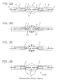
- FIG. 6 the lamp having the same structure as the lamp 1100 in FIG. 2 is shown.
- the lamp 1100 shown in FIG. 2 has the structure in which the second glass portion 7 covers a portion of the metal foil 4
- the lamp 100 shown in FIG. 6 has the structure in which the second glass portion 7 covers the whole of the metal foil 4.
- the high pressure mercury lamps 1100 to 1500 shown in FIGS. 2 to 4, 5A and 5B can be employed as the high pressure mercury lamp 100 .
- a pair of electrodes (or electrode rods) 3 are opposed to each other.
- the electrodes 3 are connected by welding to metal foils 4 , respectively.
- the metal foil 4 is typically a molybdenum foil and is provided within the sealing portion 2 . If the lamp 1100 shown in FIG. 2 is used as the high pressure mercury lamp 100 , at least a portion of the metal foil 4 is positioned in the second glass portion 7 .
- External leads 5 are connected to respective ends of the metal foils 4 .
- One of the external leads 5 is connected through a connection member 63 to a lead wire 61 .
- the other of the external leads 5 is connected through a connection member 64 to a lead wire 62 .
- a portion of the reflector 50 is formed with an air inlet 55 for introducing an air flow ( 71 ) striking against an upper portion 1a of the luminous bulb 1 and then coming into a lower portion 1b of the luminous bulb 1.
- the lamp 100 is arranged so that the sealing portions 2 and 2 extend in a substantially horizontal direction.
- the lamp 100 is arranged so that an axis 65 of the lamp 100 (for example, the center line obtained by connecting the electrodes 3 and 3 ) is substantially horizontal.
- the air vent 56 to eject heated air from the upper portion of the reflector.
- the air inlet 55 and the air vent 56 are positioned in a substantially vertical direction. In other words, the air inlet 55 is formed right below the air vent 56 , and the air vent 56 is formed right above the air inlet 55 .
Applications Claiming Priority (2)
| Application Number | Priority Date | Filing Date | Title |
|---|---|---|---|
| JP2003115538 | 2003-04-21 | ||
| JP2003115538 | 2003-04-21 |
Publications (1)
| Publication Number | Publication Date |
|---|---|
| EP1471563A2 true EP1471563A2 (de) | 2004-10-27 |
Family
ID=32959577
Family Applications (1)
| Application Number | Title | Priority Date | Filing Date |
|---|---|---|---|
| EP20040009303 Withdrawn EP1471563A2 (de) | 2003-04-21 | 2004-04-20 | Lampen mit Reflektor und entsprechenden Bildprojektionsgeräten |
Country Status (3)
| Country | Link |
|---|---|
| US (1) | US7230382B2 (de) |
| EP (1) | EP1471563A2 (de) |
| CN (1) | CN1540200A (de) |
Cited By (3)
| Publication number | Priority date | Publication date | Assignee | Title |
|---|---|---|---|---|
| WO2006099827A1 (de) * | 2005-03-21 | 2006-09-28 | Patent-Treuhand-Gesellschaft für elektrische Glühlampen mbH | Umlenkkomponente für eine leuchte und zugehörige leuchte |
| EP2600386A1 (de) * | 2010-07-26 | 2013-06-05 | Iwasaki Electric Co., Ltd | Entladungslampe mit hoher intensität |
| US8944640B2 (en) | 2012-02-06 | 2015-02-03 | Martin Professional Aps | Lamp reflector system with retro reflector |
Families Citing this family (17)
| Publication number | Priority date | Publication date | Assignee | Title |
|---|---|---|---|---|
| JP3829813B2 (ja) * | 2003-02-25 | 2006-10-04 | セイコーエプソン株式会社 | プロジェクタ |
| JP2005283706A (ja) * | 2004-03-29 | 2005-10-13 | Seiko Epson Corp | ランプ装置及びそれを備えたプロジェクタ |
| JP2006073432A (ja) * | 2004-09-03 | 2006-03-16 | Phoenix Denki Kk | 超高圧放電灯ユニットおよび光源装置 |
| WO2006030486A1 (ja) * | 2004-09-14 | 2006-03-23 | Phoenix Electric Co., Ltd. | 金属凹面反射鏡とこれを用いた光源体およびその光源装置並びにその点灯回路 |
| US20090153048A1 (en) * | 2004-10-26 | 2009-06-18 | Koninklijke Philips Electronics, N.V. | High-pressure gas discharge lamp |
| JP4492337B2 (ja) * | 2004-12-14 | 2010-06-30 | ウシオ電機株式会社 | 光源ユニット |
| JP4502885B2 (ja) * | 2005-06-01 | 2010-07-14 | 三洋電機株式会社 | 投写型表示装置 |
| JP4890809B2 (ja) * | 2005-07-28 | 2012-03-07 | ハリソン東芝ライティング株式会社 | メタルハライドランプ、メタルハライドランプ点灯装置および前照灯 |
| JP2009522741A (ja) * | 2006-01-03 | 2009-06-11 | コーニンクレッカ フィリップス エレクトロニクス エヌ ヴィ | 高圧水銀蒸気放電ランプ及び高圧水銀蒸気放電ランプを製造する方法 |
| CN101644423B (zh) * | 2008-08-08 | 2011-03-30 | 鸿富锦精密工业(深圳)有限公司 | 光源保护装置 |
| JP4991834B2 (ja) | 2009-12-17 | 2012-08-01 | シャープ株式会社 | 車両用前照灯 |
| JP5232815B2 (ja) | 2010-02-10 | 2013-07-10 | シャープ株式会社 | 車両用前照灯 |
| US20110280033A1 (en) * | 2010-05-17 | 2011-11-17 | Sharp Kabushiki Kaisha | Light-emitting device, illumination device, and vehicle headlamp |
| US8733996B2 (en) | 2010-05-17 | 2014-05-27 | Sharp Kabushiki Kaisha | Light emitting device, illuminating device, and vehicle headlamp |
| US9816677B2 (en) | 2010-10-29 | 2017-11-14 | Sharp Kabushiki Kaisha | Light emitting device, vehicle headlamp, illumination device, and laser element |
| RU2496180C1 (ru) * | 2012-03-29 | 2013-10-20 | Вячеслав Анатольевич Ермошин | Газоразрядная зеркальная лампа |
| CN104848162B (zh) * | 2014-02-19 | 2017-01-11 | 睿励科学仪器(上海)有限公司 | 一种用于高热量光源的风冷装置 |
Family Cites Families (8)
| Publication number | Priority date | Publication date | Assignee | Title |
|---|---|---|---|---|
| US3688149A (en) * | 1970-10-01 | 1972-08-29 | Westinghouse Electric Corp | Vehicle headlamp having a dual-segment reflector |
| DE3813421A1 (de) | 1988-04-21 | 1989-11-02 | Philips Patentverwaltung | Hochdruck-quecksilberdampfentladungslampe |
| JP2000200511A (ja) * | 1998-10-30 | 2000-07-18 | Phoenix Denki Kk | 放電灯 |
| DE60042943D1 (de) * | 1999-10-18 | 2009-10-22 | Panasonic Corp | Quecksilber-Hochdruckentladungslampe deren Schwärzung durch geringen Gehalt an Lithium, Natrium und Kalium verringert wird |
| JP3738678B2 (ja) * | 2000-08-04 | 2006-01-25 | ウシオ電機株式会社 | プロジェクタ用のランプユニット、およびその調光方法 |
| CN1265418C (zh) * | 2001-05-10 | 2006-07-19 | 皇家菲利浦电子有限公司 | 高压气体放电灯 |
| KR20030046318A (ko) * | 2001-12-05 | 2003-06-12 | 마쯔시다덴기산교 가부시키가이샤 | 고압방전램프의 제조방법, 고압방전램프 및 램프유닛 |
| JP3528836B2 (ja) * | 2002-01-09 | 2004-05-24 | ウシオ電機株式会社 | 放電ランプ |
-
2004
- 2004-04-20 CN CNA2004100310767A patent/CN1540200A/zh active Pending
- 2004-04-20 US US10/828,493 patent/US7230382B2/en not_active Expired - Fee Related
- 2004-04-20 EP EP20040009303 patent/EP1471563A2/de not_active Withdrawn
Cited By (5)
| Publication number | Priority date | Publication date | Assignee | Title |
|---|---|---|---|---|
| WO2006099827A1 (de) * | 2005-03-21 | 2006-09-28 | Patent-Treuhand-Gesellschaft für elektrische Glühlampen mbH | Umlenkkomponente für eine leuchte und zugehörige leuchte |
| US7748867B2 (en) | 2005-03-21 | 2010-07-06 | Osram Gesellschaft Mit Beschraenkter Haftung | Deflection component for a luminaire and associated luminaire |
| EP2600386A1 (de) * | 2010-07-26 | 2013-06-05 | Iwasaki Electric Co., Ltd | Entladungslampe mit hoher intensität |
| EP2600386A4 (de) * | 2010-07-26 | 2014-03-19 | Iwasaki Electric Co Ltd | Entladungslampe mit hoher intensität |
| US8944640B2 (en) | 2012-02-06 | 2015-02-03 | Martin Professional Aps | Lamp reflector system with retro reflector |
Also Published As
| Publication number | Publication date |
|---|---|
| CN1540200A (zh) | 2004-10-27 |
| US20040207306A1 (en) | 2004-10-21 |
| US7230382B2 (en) | 2007-06-12 |
Similar Documents
| Publication | Publication Date | Title |
|---|---|---|
| US7230382B2 (en) | High pressure mercury lamp with vented reflector and image projection apparatus | |
| US6965202B2 (en) | High pressure discharge lamp and lamp unit | |
| EP1289001A2 (de) | Hochdruckentladungslampen und Verfahren zur Herstellung einer Hochdruckentladungslampe | |
| US7198534B2 (en) | Method for manufacturing high-pressure discharge lamp, glass tube for high-pressure discharge lamp, and lamp element for high-pressure discharge lamp | |
| EP1376656A2 (de) | Hochdruck-Quecksilberlampe und Lampeneinheit | |
| US7038384B2 (en) | High pressure discharge lamp, method for producing the same and lamp unit | |
| JP2004247297A (ja) | 高圧放電ランプの製造方法、高圧放電ランプ用ガラス管、および、高圧放電ランプ用ランプ部材 | |
| EP1376655A2 (de) | Quecksilberdampf-Hochdruckentladungslampe und Lampeneinheit | |
| KR20010110145A (ko) | 방전램프, 램프 유닛 및 화상표시장치 | |
| US20040212286A1 (en) | Lamp system with reflector, high pressure discharge lamp, and image projection apparatus | |
| EP1152453A1 (de) | Hochdruckquecksilberdampfentladungslampe und lampeneinheit | |
| JP4777594B2 (ja) | 高圧放電灯およびこれを用いたランプユニット | |
| US7097528B2 (en) | Method for producing a high pressure discharge lamp, with sealing portion having first and second glass members | |
| JP4609224B2 (ja) | 光源装置 | |
| JPH11102663A (ja) | 金属蒸気放電ランプおよび投光装置 | |
| JP2004342600A (ja) | 反射鏡付きランプ、高圧放電ランプおよび画像投影装置 | |
| JP2004342599A (ja) | 反射鏡付きランプおよび画像投影装置 | |
| US7097529B2 (en) | Method for producing a high pressure discharge lamp, with sealing portion having first and second glass members | |
| JP2007299621A (ja) | 高圧放電ランプおよび照明装置 | |
| JP2001102001A (ja) | 短アーク形のメタルハライド放電ランプ、メタルハライド放電ランプ装置および照明装置 | |
| JP2002170523A (ja) | 高圧放電ランプおよび照明装置 | |
| JP2004241375A (ja) | 高圧放電ランプの製造方法、高圧放電ランプおよびランプユニット | |
| JP2004221069A (ja) | 高圧放電ランプの製造方法、高圧放電ランプおよびランプユニット | |
| JP2005302676A (ja) | 高圧放電ランプおよび照明装置 | |
| JPH1196970A (ja) | 放電ランプ用バルブ、放電ランプおよび照明装置 |
Legal Events
| Date | Code | Title | Description |
|---|---|---|---|
| PUAI | Public reference made under article 153(3) epc to a published international application that has entered the european phase |
Free format text: ORIGINAL CODE: 0009012 |
|
| AK | Designated contracting states |
Kind code of ref document: A2 Designated state(s): AT BE BG CH CY CZ DE DK EE ES FI FR GB GR HU IE IT LI LU MC NL PL PT RO SE SI SK TR |
|
| AX | Request for extension of the european patent |
Extension state: AL HR LT LV MK |
|
| STAA | Information on the status of an ep patent application or granted ep patent |
Free format text: STATUS: THE APPLICATION HAS BEEN WITHDRAWN |
|
| 18W | Application withdrawn |
Effective date: 20050512 |