EP1376656A2 - Hochdruck-Quecksilberlampe und Lampeneinheit - Google Patents
Hochdruck-Quecksilberlampe und Lampeneinheit Download PDFInfo
- Publication number
- EP1376656A2 EP1376656A2 EP03014390A EP03014390A EP1376656A2 EP 1376656 A2 EP1376656 A2 EP 1376656A2 EP 03014390 A EP03014390 A EP 03014390A EP 03014390 A EP03014390 A EP 03014390A EP 1376656 A2 EP1376656 A2 EP 1376656A2
- Authority
- EP
- European Patent Office
- Prior art keywords
- luminous bulb
- high pressure
- bulb
- pressure mercury
- mercury lamp
- Prior art date
- Legal status (The legal status is an assumption and is not a legal conclusion. Google has not performed a legal analysis and makes no representation as to the accuracy of the status listed.)
- Withdrawn
Links
Images


Classifications
-
- H—ELECTRICITY
- H01—ELECTRIC ELEMENTS
- H01J—ELECTRIC DISCHARGE TUBES OR DISCHARGE LAMPS
- H01J61/00—Gas-discharge or vapour-discharge lamps
- H01J61/02—Details
- H01J61/12—Selection of substances for gas fillings; Specified operating pressure or temperature
- H01J61/18—Selection of substances for gas fillings; Specified operating pressure or temperature having a metallic vapour as the principal constituent
- H01J61/20—Selection of substances for gas fillings; Specified operating pressure or temperature having a metallic vapour as the principal constituent mercury vapour
-
- H—ELECTRICITY
- H01—ELECTRIC ELEMENTS
- H01J—ELECTRIC DISCHARGE TUBES OR DISCHARGE LAMPS
- H01J61/00—Gas-discharge or vapour-discharge lamps
- H01J61/02—Details
- H01J61/54—Igniting arrangements, e.g. promoting ionisation for starting
- H01J61/547—Igniting arrangements, e.g. promoting ionisation for starting using an auxiliary electrode outside the vessel
-
- H—ELECTRICITY
- H01—ELECTRIC ELEMENTS
- H01J—ELECTRIC DISCHARGE TUBES OR DISCHARGE LAMPS
- H01J61/00—Gas-discharge or vapour-discharge lamps
- H01J61/02—Details
- H01J61/24—Means for obtaining or maintaining the desired pressure within the vessel
- H01J61/26—Means for absorbing or adsorbing gas, e.g. by gettering; Means for preventing blackening of the envelope
-
- H—ELECTRICITY
- H01—ELECTRIC ELEMENTS
- H01J—ELECTRIC DISCHARGE TUBES OR DISCHARGE LAMPS
- H01J61/00—Gas-discharge or vapour-discharge lamps
- H01J61/02—Details
- H01J61/36—Seals between parts of vessels; Seals for leading-in conductors; Leading-in conductors
- H01J61/366—Seals for leading-in conductors
-
- H—ELECTRICITY
- H01—ELECTRIC ELEMENTS
- H01J—ELECTRIC DISCHARGE TUBES OR DISCHARGE LAMPS
- H01J61/00—Gas-discharge or vapour-discharge lamps
- H01J61/02—Details
- H01J61/52—Cooling arrangements; Heating arrangements; Means for circulating gas or vapour within the discharge space
- H01J61/523—Heating or cooling particular parts of the lamp
-
- H—ELECTRICITY
- H01—ELECTRIC ELEMENTS
- H01J—ELECTRIC DISCHARGE TUBES OR DISCHARGE LAMPS
- H01J61/00—Gas-discharge or vapour-discharge lamps
- H01J61/82—Lamps with high-pressure unconstricted discharge having a cold pressure > 400 Torr
- H01J61/822—High-pressure mercury lamps
-
- H—ELECTRICITY
- H01—ELECTRIC ELEMENTS
- H01J—ELECTRIC DISCHARGE TUBES OR DISCHARGE LAMPS
- H01J61/00—Gas-discharge or vapour-discharge lamps
- H01J61/84—Lamps with discharge constricted by high pressure
- H01J61/86—Lamps with discharge constricted by high pressure with discharge additionally constricted by close spacing of electrodes, e.g. for optical projection
Definitions
- the present invention relates to a high pressure mercury lamp and a lamp unit.
- the present invention relates to a high pressure mercury lamp enclosing a comparatively large amount of mercury among high pressure mercury lamps used as a light source of projectors or the like.
- image projecting apparatuses such as liquid crystal projectors or DMD projectors have been widely used.
- a high pressure mercury lamp as disclosed in Japanese Laid-Open Patent Publication No. 2-148561 is commonly used in a wide range.
- FIG. 1 shows the structure of the high pressure mercury lamp disclosed in Japanese Laid-Open Patent Publication No. 2-148561.
- a lamp 1000 shown in Figure 1 includes a luminous bulb 1 mainly made of quartz glass, and a pair of side tube portions (sealing portions) 2 extending from both ends thereof. Metal electrode structures are buried in the side tube portions 2 so that power can be supplied to the luminous bulb from the outside.
- the electrode structure has a structure in which an electrode 3 made of tungsten (W), a molybdenum (Mo) foil 4 , and an external lead wire 5 are electrically connected sequentially in this order.
- a coil 12 is wound around the head of the electrode 3 .
- mercury (Hg) which is a luminous species
- the operational principle of the lamp 1000 will be described.
- a start voltage is applied to both ends of the pair of external lead wires 5 , discharge of Ar occurs, and the temperature in the luminous bulb 1 increases.
- Hg atoms evaporate and fill the luminous bulb 1 in the form of gas.
- the Hg atoms are excited by electrons released from one electrode 3 and become luminous between the two electrodes 3 . Therefore, as the vapor pressure of Hg, which is the luminous species, is higher, light having a higher intensity is released.
- the potential difference (voltage) between the two electrodes is larger, so that current can be reduced when the lamp is operated with the same rated power. This means that a burden to the electrode 3 can be reduced, which leads to a longer lifetime of the lamp. Therefore, as the Hg vapor pressure is larger, a lamp having better characteristics in terms of the intensity and the lifetime can be obtained.
- Japanese Laid-Open Patent Publication No. 2-148561 discloses a superhigh pressure mercury lamp used at a Hg vapor pressure of 200 bar to 350 bar (equivalent to about 20 MPa to about 35 MPa), but in a realistic use in view of the reliability and the lifetime or the like, the lamp is used at a Hg vapor pressure of about 15 MPa to 20 MPa (150 to 200 atm).
- This high pressure mercury lamp having a very high withstand pressure is operated at a high mercury vapor pressure that cannot be achieved in the conventional technique, and therefore the characteristics and the behavior cannot be predicted.
- the inventors of the present invention made operation tests of the high pressure mercury lamp, it was found that the lamp is blackened when the operating pressure exceeds 20 MPa, which is the conventional operating pressure, especially reaches generally 30 MPa or more.
- a high pressure mercury lamp of the present invention includes a luminous bulb in which at least mercury is enclosed inside the bulb, and a pair of sealing portions that retain airtightness of the luminous bulb. At least one of the sealing portions has a first glass portion extending from the luminous bulb and a second glass portion provided in at least a portion inside the first glass portion, and the one of the sealing portions has a portion to which a compressive stress is applied. Furthermore, a heating wire is provided at least at part of the luminous bulb and the pair of sealing portions.
- the amount of the enclosed mercury is 230 mg/cm 3 or more based on the volume of the luminous bulb.
- the amount of the enclosed mercury is 300 mg/cm 3 or more based on the volume of the luminous bulb, halogen is enclosed in the luminous bulb, the bulb wall load of the high pressure mercury lamp is 80 W/cm 2 or more, and the heating wire is means for heating the luminous bulb.
- the heating wire may be wound around at least one of the sealing portions.
- external lead wires are extending from end portions of the pair of sealing portions, and one end of the heating wire is electrically connected to at least one of the external lead wires.
- a switch for turning on and off an electrical connection with the external lead wire is provided in a portion of the heating wire.
- the heating wire is electrically connected to the external lead wire before operation, and after operation, the electrical connection with the external lead wire is disconnected, and the heating wire is electrically connected to a power source for supplying current to the heating wire.
- a switch for disconnecting an electrical connection with the external lead wire is provided in a portion of the heating wire.
- a pair of electrode rods are opposed to each other in the luminous bulb, at least one of the pair of electrode rods is connected to a metal foil, and the metal foil is provided in the sealing portion, and at least a portion of the metal foil is positioned in the second glass portion.
- a coil having at least one metal selected from the group consisting of Pt, Ir, Rh, Ru, and Re at least on its surface is wound around at least in a portion of the electrode rod that is buried in the at least one of the sealing portions.
- a metal portion that is in contact with the second glass portion and supplies power is provided in the sealing portions, the compressive stress is applied at least in the longitudinal direction of the sealing portions, the first glass portion contains 99 wt% or more of SiO 2 , and the second glass portion contains SiO 2 and at least one of 15 wt% or less of Al 2 O 3 and 4 wt% or less of B.
- Another high pressure mercury lamp of the present invention includes a luminous bulb in which at least mercury is enclosed inside the bulb and a pair of electrode rods are opposed, and a pair of sealing portions extending from the luminous bulb.
- a coil having at least one metal selected from the group consisting of Pt, Ir, Rh, Ru, and Re at least on its surface is wound around at least in a portion of the electrode rod that is buried in at least one of the sealing portions, and a heating wire is provided at least at part of the luminous bulb and the pair of sealing portions.
- Yet another high pressure mercury lamp of the present invention includes a luminous bulb in which at least mercury is enclosed inside the bulb, and a pair of sealing portions that retain airtightness of the luminous bulb.
- the amount of the enclosed mercury is 230 mg/cm 3 or more based on the volume of the luminous bulb, and heating means for heating the luminous bulb is provided at least at part of the luminous bulb and the pair of sealing portions.
- the heating means is a heating wire
- the amount of the enclosed mercury is 300 mg/cm 3 or more based on the volume of the luminous bulb
- halogen is enclosed in the luminous bulb
- the bulb wall load of the high pressure mercury lamp is 80 W/cm 2 or more.
- the high pressure mercury lamp may further include means for measuring the temperature of the luminous bulb.
- the means for measuring the temperature is a thermocouple.
- the heating means is configured so as to heat the luminous bulb at the same time as operation is started or after operation is started
- a high pressure mercury lamp in an embodiment includes a luminous bulb in which a pair of electrodes are opposed in the bulb, and sealing portions extending from the luminous bulb and having a portion of the electrode inside.
- a metal film constituted by at least one metal selected from the group consisting of Pt, Ir, Rh, Ru, and Re is formed on a surface at least in a portion of the electrode that is positioned inside the sealing portions.
- the electrodes are connected to the metal foils provided in the sealing portions by welding, and the metal film is not formed in the connection portion with the metal foils and is formed on the surface of the electrodes that is buried in the sealing portions.
- a portion of the metal constituting the metal film may be present in the luminous bulb. It is preferable that the metal film has a multilayered structure including an Au layer as the lower layer and a Pt layer as the upper layer.
- a high pressure mercury lamp in an embodiment includes a luminous bulb in which a pair of electrodes are opposed in the bulb, and a pair of sealing portions extending from the luminous bulb and having a portion of the electrode inside.
- a coil having at least one metal selected from the group consisting of Pt, Ir, Rh, Ru, and Re on its surface is wound around a portion of the electrode that is positioned inside the sealing portions.
- the metal foil and a portion of the electrode are buried in the sealing portions, and a coil having at least one metal selected from the group consisting of Pt, Ir, Rh, Ru, and Re on its surface is wound around the electrode that is buried in the sealing portions. It is preferable that the coil has a metal film having a multilayered structure including an Au layer as the lower layer and a Pt layer as the upper layer on its surface.
- a high pressure mercury lamp in one embodiment includes a luminous bulb enclosing a luminous substance inside; and sealing portions for retaining airtightness of the luminous bulb.
- the sealing portion has a first glass portion extending from the luminous bulb and a second glass portion provided at least in a portion inside the first glass portion.
- the sealing portion has a portion to which a compressive stress is applied.
- the portion to which a compressive stress is applied is one selected from the group consisting of the second glass portion, a boundary portion of the second glass portion and the first glass portion, a portion of the second glass portion on the side of the first glass portion, and a portion of the first glass portion on the side of the second glass portion.
- a strain boundary region caused by a difference in the compressive stress between the first glass portion and the second glass portion is present in the vicinity of the boundary of the two glass portions. It is preferable that a metal portion for supplying power that is in contact with the second glass portion is provided in the sealing portion.
- the compressive stress may be applied at least in the longitudinal direction of the sealing portion.
- the first glass portion contains 99 wt% or more of SiO 2
- the second glass portion contains SiO 2 and at least one of 15 wt% or less of Al 2 O 3 and 4 wt% or less of B.
- the softening point of the second glass portion is lower than that of the first glass portion.
- the second glass portion is formed of a glass tube. It is preferable that the second glass portion is not formed by compressing and sintering glass powder.
- the compressive stress in the portion to which the compressive stress is applied is about 10 kgf/cm 2 or more and about 50 kgf/cm 2 or less, or the difference in the compressive stress is about 10 kgf/cm 2 or more and about 50 kgf/cm 2 or less.
- a pair of electrode rods are opposed in the luminous bulb, at least one of the pair of electrode rods is connected to a metal foil, and the metal foil is provided in the sealing portion, and at least a portion of the metal foil is positioned in the second glass portion.
- At least mercury is enclosed in the luminous bulb as the luminous substance, and the amount of the mercury enclosed is 300 mg/cc or more.
- the general color rendering index Ra of the high pressure mercury lamp is more than 65. It is preferable that the color temperature of the high pressure mercury lamp is 8000 K or more.
- a lamp unit of the present invention includes a high pressure mercury lamp and a reflecting mirror for reflecting light emitted from the high pressure mercury lamp.
- the high pressure mercury lamp includes a luminous bulb in which at least mercury is enclosed inside the bulb, and a pair of sealing portions that retain airtightness of the luminous bulb.
- At least one of the sealing portions has a first glass portion extending from the luminous bulb and a second glass portion provided in at least a portion inside the first glass portion, and the one of the sealing portions has a portion to which a compressive stress is applied, and a heating wire is provided at least at part of the luminous bulb and the pair of sealing portions.
- the high pressure mercury lamp includes a luminous bulb in which at least mercury is enclosed inside the bulb, and a pair of sealing portions that retain airtightness of the luminous bulb. At least one of the sealing portions has a first glass portion extending from the luminous bulb and a second glass portion provided in at least a portion inside the first glass portion, and the one of the sealing portions has a portion to which a compressive stress is applied, and a heating wire is provided at least at a portion of the reflecting mirror.
- the amount of the enclosed mercury is 230 mg/cm 3 or more based on the volume of the luminous bulb.
- Yet another lamp unit of the present invention includes a high pressure mercury lamp and a reflecting mirror for reflecting light emitted from the high pressure mercury lamp.
- the high pressure mercury lamp includes a luminous bulb in which at least mercury is enclosed inside the bulb, and a pair of sealing portions that retain airtightness of the luminous bulb.
- the amount of the enclosed mercury is 230 mg/cm 3 or more based on the volume of the luminous bulb, and heating means for heating the luminous bulb is provided at least at part of the luminous bulb and the pair of sealing portions.
- the amount of the enclosed mercury is 300 mg/cm 3 or more based on the volume of the luminous bulb, halogen is enclosed in the luminous bulb, and the bulb wall load of the high pressure mercury lamp is 80 W/cm 2 or more.
- the lamp unit further includes means for measuring the temperature of the luminous bulb.
- the means for measuring the temperature is a thermocouple, and the thermocouple is provided in at least one selected from the group consisting of a portion of the high pressure mercury lamp, a portion of the reflecting mirror and a portion of a lamp system to which the reflecting mirror is to be incorporated.
- the heating means is a heating wire, and the heating wire serves as a trigger wire.
- a high pressure mercury lamp that can withstand a very high pressure such as an operating pressure of about 30 to 40 MPa or more (about 300 to 400 atm or more) will be described.
- a very high pressure such as an operating pressure of about 30 to 40 MPa or more (about 300 to 400 atm or more)
- the details of such a high pressure mercury lamp are disclosed in Patent Application Nos. 2001-267487 and 2001-371365, which are incorporated herein by reference.
- FIG. 2B is a cross-sectional view taken along line b-b in Figure 2A .
- the high pressure mercury lamp 1100 shown in Figure 2 is disclosed in Patent Application No. 2001-371365, and includes a luminous bulb 1 and a pair of sealing portions 2 for retaining the airtightness of the luminous bulb 1 .
- At least one of the sealing portions 2 has a first glass portion 8 extending from the luminous bulb 1 and a second glass portion 7 provided in at least a portion inside of the first glass portion 8, and the one sealing portion 2 has a portion ( 20 ) in which a compression stress is applied.
- the first glass portion 8 in the sealing portion 2 contains at least 99 wt% of SiO 2 , and is made of quartz glass, for example.
- the second glass portion 7 contains SiO 2 and at least one of 15 wt% or less of Al 2 O 3 and 4 wt% or less of B, and is made of Vycor glass, for example.
- Al 2 O 3 or B is added to SiO 2 , the softening point of the glass is decreased, so that the softening point of the second glass portion 7 is lower than that of the first glass portion 8 .
- Vycor glass product name
- the composition thereof is, for example, 96.5 wt% of silica (SiO 2 ), 0.5 wt% of alumina (Al 2 O 3 ) and 3 wt% of boron (B).
- the second portion 7 is formed of a glass tube made of Vycor glass.
- a glass tube containing 62 wt% of SiO 2 , 13.8 wt% of Al 2 O 3 and 23.7 wt% of CuO can be used.
- the compression stress applied into a portion of the sealing portion 2 is substantially more than 0 (that is, 0 kgf/cm 2 ).
- the presence of this compression stress can improve the strength against pressure over a conventional structure.
- the compression stress is about 10 kgf/cm 2 or more (about 9.8 ⁇ 10 5 N/m 2 or more) and about 50 kgf/cm 2 or less (about 4.9 ⁇ 10 6 N/m 2 or less).
- the compression strain may be weak so that the strength against pressure of the lamp may not be increased sufficiently.
- the compression stress is preferably less than 50 kgf/cm 2 .
- the compression stress is less than 10 kgf/cm 2 , if it substantially exceeds 0, the withstand pressure can be higher than that of the conventional structure.
- the second glass portion 7 can have a compression stress of more than 50 kgf/cm 2 .
- An electrode rod 3 whose one end is positioned in the discharge space is connected to a metal foil 4 provided in the sealing portion 2 by welding, and at least a portion of the metal foil 4 is positioned in the second glass portion 7 .
- a portion including the connection portion of the electrode rod 3 and the metal foil 4 is covered with the second glass portion 7 .
- the size of the second glass portion 7 in the structure shown in Figure 2 is, for example, as follows: the length in the longitudinal direction of the sealing portion 2 is about 2 to 20 mm (e.g., 3 mm, 5 mm or 7 mm), and the thickness of the second glass portion 7 sandwiched between the first glass portion 8 and the metal foil 4 is about 0.01 to 2 mm (e.g., 0.1 mm).
- the distance H which is from the end face of the second glass portion 7 on the luminous bulb 1 side to the discharge space of the luminous bulb 1 is, for example, 0 mm to about 3 mm.
- the distance B which is from the end face of the metal foil 4 on the luminous bulb 1 side to the discharge space of the luminous bulb 1 is, for example, about 3 mm.
- a high pressure mercury lamp 1200 shown in Figure 3 has a structure in which a coil 40 having a metal of at least one selected from the group consisting of Pt, Ir, Rh, Ru, and Re on its surface is wound around the portion of the electrode 3 that is positioned in the sealing portion 2 .
- the coil 40 typically has a metal film having a multilayered structure of an Au layer as the lower layer and a Pt layer as the upper layer on its surface.
- a metal film 30 formed of at least one selected from the group consisting of Pt, Ir, Rh, Ru, and Re is formed on the surface of at least a portion of the electrode 3 that is positioned in the sealing portion 2 , as shown in the high pressure mercury lamp 1300 shown in Figure 4 , which may be somewhat a disadvantage in production process in mass production.
- High pressure mercury lamps 1400 and 1500 having structures employing the coil 40 or the metal film 30 without using the second glass portion 7 , as shown in Figures 5A and 5B can realize an operating pressure of 30 MPa or more in the level in which the lamp can operate in practical use, although the withstand pressure becomes lower than that of the structures shown in Figures 2 to 4 .
- a lamp in which the Hg vapor pressure during operation exceeds 30 MPa (300 atm) as shown in Figure 2 was produced as a sample and the inventors of the present invention made operation tests. Then, it was found that when the operating pressure reaches about 30 MPa or more, the lamp is blackened. Blackening is a phenomenon that occurs when the temperature of the W electrode 3 is increased during operation and W (tungsten) evaporated from the W electrode is attached onto the inner wall of the luminous bulb, and if the lamp constitutes to be operated, it will be broken.
- a halogen gas enclosed in the luminous bulb reacts with tungsten attached onto the inner wall of the luminous bulb to be converted into tungsten halide.
- the tungsten halide floats in the luminous bulb and reaches the head of the W electrode having a high temperature, the tungsten halide is dissociated into halogen and tungsten, which is the original state, so that the tungsten returns to the head of the electrode.
- halogen cycle At the Hg vapor pressure of the conventional lamp, the lamp can be operated without being blackened because of this cycle.
- the inventors of the present invention found that the blackening problem can be solved by controlling the temperature of the luminous bulb 1 , and achieved the present invention.
- embodiments of the present invention will be described. However, the present invention is not limited to the following embodiments.
- Figure 6A shows a high pressure mercury lamp 100 having an amount of enclosed mercury 6 of 230 mg/cm 3 or more.
- the high pressure mercury lamp 100 is typically the high pressure mercury lamps 1100 to 1500 shown in Figures 2 to 5A and 5B .
- the high pressure mercury lamp 100 shown in Figure 6A includes a luminous bulb 1 enclosing at least mercury 6 inside and a pair of sealing portions 2 for retaining the airtightness of the luminous bulb 1 .
- the amount of the enclosed mercury 6 is 230 mg/cm 3 or more (e.g., 250 mg/cm 3 or more or 300 mg/cm 3 or more, and more than 350 mg/cm 3 or 350 mg/cm 3 to 400 mg/cm 3 or more in some cases) based on the volume of the luminous bulb 1 .
- a pair of electrodes (or electrode rods) 3 are opposed to each other, and the electrodes 3 are connected to metal foils 4 by welding.
- the metal foils 4 are typically molybdenum foils and are provided in the sealing portions 2 .
- the high pressure mercury lamp 100 is the lamp 1100 shown in Figure 2
- at least a portion of the metal foil 4 is positioned inside the second glass portion 7 .
- FIG 6B shows the structure of a high pressure mercury lamp 200 of this embodiment.
- the high pressure mercury lamp 200 is obtained by providing heating means 10 for heating the luminous bulb 1 at the lamp 100 shown in Figure 6A .
- the heating means 10 is a heating wire and is wound around at least a portion of the luminous bulb 1 and the pair of sealing portions 2 .
- the heating wire 10 is wound around the sealing portion 2 . More specifically, the heating wire 10 is wound from one of the sealing portions 2 and wound around the other sealing portion 2 , straddling the luminous bulb 1 .
- the number of windings is about 30 revolutions.
- a kanthal wire which is hardly oxidized, is used as the heating wire 10 .
- the lamp 100 (or 200 ) includes a luminous bulb 1 made mainly of quartz and a pair of sealing portions (side tube portions) 2 extending from both ends of the luminous bulb and is a double end type lamp having two sealing portions 2 .
- the luminous bulb 1 is substantially spherical, and the outer diameter is, for example, about 5 mm to 20 mm, and the thickness of the glass is, for example, about 1 mm to 5 mm.
- the volume of the discharge space of the luminous bulb 1 is, for example, about 0.01 cc to 1 cc (0.01 cm 3 to 1 cm 3 ).
- the luminous bulb 1 having an outer diameter of about 10 mm, a thickness of the glass of about 3 mm, and a volume of the discharge space of the luminous bulb 1 of about 0.06 cc is used.
- a pair of electrode rods 3 are opposed in the luminous bulb 1 .
- the heads of the electrode rods 3 are provided in the luminous bulb with a distance (arc length) of about 0.2 to 5 mm. In this embodiment, the arc length is 0.5 to 1.8 mm.
- the lamp of this embodiment is operated with AC current.
- the sealing portion 2 has a shrink structure produced by a shrinking approach.
- mercury 6 which is the luminous species, is enclosed in an amount of 300 mg/cc or more. In this embodiment, mercury is enclosed in an amount of 400 mg/cc.
- a rare gas (e.g., Ar) with 5 to 40 kPa and, if necessary, a small amount of halogen are enclosed.
- Ar with 20 kPa is enclosed, and halogen is enclosed in the form of CH 2 Br 2 in the luminous bulb.
- the amount of the enclosed CH 2 Br 2 is about 0.0017 to 0.17 mg/cc, which corresponds to about 0.01 to 1 ⁇ mol / cc in terms of the halogen atom density during lamp operation. In this embodiment, it is about 0.1 ⁇ mol / cc.
- the bulb wall load applied to the inner wall of the luminous bulb during operation is, for example, 60 W /cm 2 or more. In this embodiment, the lamp is operated at 120 W and the bulb wall load is about 150 W /cm 2 .
- the lamp 200 is electrically connected to a ballast 32
- the heating wire 10 is electrically connected to a power source unit 22 . More specifically, both ends 11 of the heating wire 10 are connected to the power source unit 22 , and the ends of the external lead wires 5 are connected to the ballast 32 .
- the ballast 32 is switched on to operate the lamp 200 .
- the power source unit 22 is operated to heat the lamp 200 .
- the power source unit 22 can be operated at the same time when the ballast 32 is operated, or can be operated within a few minutes later.
- the power required to heat the heating wire 10 is suitably about 10 to 50 W. In this embodiment, a power of 10 W is supplied.
- Ten lamps 100 without the heating wire 10 and ten lamps 200 of this embodiment are operated for several hours.
- the amount of the enclosed mercury is 350 mg/cc for all the twenty lamps.
- the lamps 100 without the heating wire 10 are the lamps 1100 shown in Figure 2 and the lamps 200 are configured simply by winding the heating wire 10 around the lamp 1100 .
- the lamps 100 were operated by connecting only ballast 32 to both ends of the external lead wires 5 .
- the lamps 200 were connected to the ballast 32 at both the ends of the external lead wires 5 , and after the lamps were operated, the power source unit 22 connected to both the ends 11 of the heating wire 10 allowed current to flow through the heating wire 10 so as to increase the temperature of the luminous bulb 1 .
- the lamps 100 were operated for several hours, and all the lamps are blackened.
- the lamps 200 continued to be operated without being blackened. This seems to be because the halogen cycle worked well by changing the temperature of the lamps (in particular, the temperature in the luminous bulb 1 ). This aspect will be described in detail later.
- the inventors of the present invention prepared the lamps 100 and 200 having an amount of enclosed mercury of 250, 300, and 350 mg/cc (three lamps for each amount are prepared). These lamps were operated for several hours in the same manner as in the above experiments.
- the lamps 100 all the lamps with 300 mg/cc or more were blackened and broken. However, the lamp having an amount of enclosed mercury of 250 mg/cc were not blackened. On the other hand, with the structure of the lamp 200, all the lamps were operated without being blackened.
- the inventors of the present invention attempted various measures and modifications to prevent blackening. For example, it was confirmed that in the lamps having an operating pressure of 30 MPa or more, the temperature of the lamp (in particular, the luminous bulb) was increased more than in the lamps with 15 MPa to 20 MPa. Then, the inventors suspected that this increase might be a cause of blackening, and decreased the temperature of the luminous bulb by cooling the luminous bulb during lamp operation. However, blackening was not prevented. They made various other attempts, but blackening was not prevented well.
- the lamps having an operating pressure of 30 MPa enclose a larger amount of Hg, which is the luminous species, than that of regular lamps. Therefore, electrons released from the electrodes collide with Hg atoms more often than the lamps having an operating pressure of 20 MPa, and Hg excites in a larger frequency. Furthermore, the electron mobility is decreased so that the arc is narrower than that of the lamps of 20 MPa. As a result, the energy per unit volume of the arc is larger and therefore an arc having a higher intensity and a higher temperature. Therefore, the temperature of the heads of the electrodes is increased, and tungsten evaporates more than that in the lamp of 20 MPa.
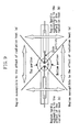
- Figure 8 shows the optical spectrum of lamps having an operating pressure of 20 MPa and 40 MPa.
- the radiation heat from the arc is larger when the operating pressure is larger. This is because the temperature difference between the region susceptible to the effect of the radiation heat from the arc ((a) in Figure 9 ) and the region hardly susceptible to the effect of the radiation heat ((b) in Figure 9 ) is enlarged by the larger radiation heat.
- the temperature balance in the luminous bulb that is maintained in the lamp of 20 MPa collapses in the lamp of 30 MPa.
- a convection in the luminous bulb is larger and heat is carried from the lower portion of the luminous bulb to the upper portion so that the temperature balance also collapses in the upper and the lower portions.
- the inventors of the present invention found that blackening can be prevented by positively controlling the temperature of the luminous bulb 1 , and provided the heating means ( 10 ) at the lamp. It seems that by positively controlling the temperature of the luminous bulb 1, a reaction W + Br 2 ⁇ WBr 2 in the inner wall of the luminous bulb was accelerated by a temperature increase, and as a result, W attached onto the inner wall of the luminous bulb succeeded in returning to the electrodes.
- the lamps of 30 MPa or more are blackened, but in order to guarantee that blackening does not occur for a long time with respect to lamps of 30 MPa or less, but more than 20 MPa (i.e., lamps having an operating pressure exceeding the conventional operating pressure of 15 MPa to 20 MPa, for example, lamps of 23 MPa or more or 25 MPa or more), it is desirable in practical use to provide the heating means (heating wire) 10 so as to control the temperature of the luminous bulb 1 positively to suppress blackening.
- the heating means (heating wire) 10 so as to control the temperature of the luminous bulb 1 positively to suppress blackening.
- the heating means (heating wire) 10 in the lamps having an operating pressure exceeding the conventional operation pressure of 15 MPa to 20 MPa.
- the effect of blackening is larger as the operating pressure is larger, in other words, the effect of blackening is larger in a lamp of 40 MPa than in a lamp of 30 MPa, and therefore it is needless to say that the technical significance of blackening suppression by the heating means (heating wire) 10 is larger as the operating pressure is larger.
- the results of measuring the temperature of the lamps 100 and 200 using a radiation thermometer will be described.
- the heating wire 10 was wound around the sealing portion 2 of the lamp 100 and thus the lamp 200 was produced and the lamp 200 was operated in the manner as shown in Figure 7 .
- the lamps 200 and 100 are the same lamps except one difference of whether or not the heating wire 10 is provided.
- the temperatures of the lamps 100 and 200 were measured 30 minutes after the operation, and for each lamp, the temperatures in three portion, that is, the upper outer surface of the luminous bulb (A in Figure 7), the lower outer surface thereof (B in Figure 7), and the side portion thereof (C in Figure 7) were measured.
- Figure 10 shows the measurement results.
- the temperature in the upper portion A was 920°C
- the temperature in the lower portion B was 780°C
- the temperature in the side portion C was 700°C.
- the temperature in the upper portion A was 930°C
- the temperature in the lower portion B was 820°C
- the temperature in the side portion C was 840°C.
- the temperature was increased by 10°C in the upper portion of the luminous bulb 1 , 40°C in the lower portion of the luminous bulb 1 and 140°C in the side portion of the luminous bulb 1 by heating the lamp with the heating means 10 .
- the temperature distribution of the luminous bulb 1 is changed by configuring a lamp so as to have means for heating the lamp, and thus the temperature condition in which blackening does not occur was created intentionally.
- Figures 11 and 12 show a change in the power and the current over time, respectively.
- the vertical axis of Figure 11 indicates power, and one scale represents 100 W.
- the horizontal axis shows time, and one scale represents 20 seconds.
- the power is increased gradually immediately after the start of the operation of the lamps, and when the power reached an operating power of 120 W at a certain time and then became constant.
- the time was 115 seconds for the lamp 100 and 83 seconds for the lamp 200 .
- heating the luminous bulb advanced the time at which the power reached the operating power by about 30 seconds or more.
- the magnitude of the power is reflected on the luminous flux and the time at which the luminous flux rises is also advanced by about 30 seconds, and the structure of the lamp 200 has an effect of reducing the luminous flux rise time.
- the vertical axis of Figure 12 indicates current, and one scale represents 1 A.
- the horizontal axis shows time, and one scale represents 20 seconds. Since Hg evaporates only in a small amount immediately after the start of the operation of the lamp, the voltage is very small, as seen from Figure 12 . Therefore, a large current flows, but in order to reduce a load to the electrodes, the current value that flows in this early stage is limited by the ballast. This is referred to as a "limited current".
- the limited current flows for a while, and when Hg evaporates sufficiently, the voltage is increased, and the current value begins to be decreased at a certain time.
- the time during which the limited current flow is shorter the load to the electrodes is smaller, and a lamp having a long lifetime can be provided.
- the current value is measured, the time during which the limited current was 115 seconds for the lamp 100 and 83 seconds for the lamp 200 .
- the time is about 30 seconds shorter in the lamp 200 . This means that the lamp 200 of this embodiment has a smaller load to the elements and has a structure that is effective to prolong the lifetime.
- the high pressure mercury lamp of this embodiment is provided with the heating means (heating wire) 10 for heating the luminous bulb 1 , so that even if the amount of enclosed mercury is 230 mg/cm 3 or more (e.g., 300 mg/cm 3 or more), blackening can be suppressed.
- the heating wire 10 is wound around the sealing portions 2 on both sides, straddling the luminous bulb 1 , but as shown in Figure 13 , the heating wire 10 may be wound separately each of the pair of sealing portions 2 . Alternatively, the heating wire 10 may be wound around only one of the sealing portions 2 . When the heating wire 10 is wound around only one of the sealing portions 2, it is possible to adjust the temperature by providing a heat reserving film in the other sealing portion 2 . Furthermore, the heating wire 10 can be wound around the sealing portions 2 such a manner that a portion of the luminous bulb 1 is also covered.
- a kanthal wire which is hardly oxidized, is used as the heating wire, but other heating wires such as a nichrome wire may be used.
- the present invention is not limited thereto, and other heating means such as a halogen heater or a high frequency induction heating apparatus can be used.
- the portion to be heated is typically a position including the outer circumference of a portion of the sealing portion 2 in which the electrode 3 is buried (position of the sealing portion 2 on the side of the luminous bulb 1 ), as shown in Figure 6B , but the present invention is not limited thereto and any position can be used, as long as the temperature of the luminous bulb 1 is controlled to suppress blackening.
- the position may be a position including the outer circumference of a portion of the sealing portion 2 in which the external lead wire 5 is buried (position of the sealing portion 2 on the side of the external lead wire 5 ).
- the heating wire (heating means) 10 can be wound around the mirror.
- the heating means 10 may be arranged in a portion of a lamp system in which a lamp or a lamp unit is incorporated.
- a front glass 510 is provided in a front opening portion of the mirror 500 of a lamp unit for airtightness, as shown in Figures 15 and 16 , for the unlikely event that the high pressure mercury lamp 200 is broken.
- a non-airtightness type mirror can be used. It is possible to integrate the power unit 22 and the ballast 32 into one piece in order to reduce the size of the apparatus.
- Embodiment 2 will be described.
- the structure of this embodiment is obtained by further adding a temperature control function to the structure of Embodiment 1.
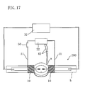
- thermocouple 40 is attached to a portion a of the lamp 200 as shown in Figure 17 .
- the function to control the temperature can be added. If the temperature measuring means ( 40 ) is provided in this manner, the temperature can be controlled more precisely.
- a measuring system for measuring the temperature is incorporated in the power unit 22 , and is configured so as to control as follows.
- a switch 50 is turned on to flow current through the heating wire 10 , whereas when the measured temperature is higher than the defined temperature, the switch 50 is turned off.
- the heating wire 10 functions as a radiation wire and therefore has an effect of reducing the temperature. Therefore, the temperature can be adjusted smoothly.
- the temperature measurement is not necessarily performed with the thermocouple, and infrared radiation can be measured.
- the sealing portion of the lamp e.g., b in Figure 17
- a portion of the mirror e.g., c in Figure 16
- any suitable temperature measuring means and portions for measurement can be used, as long as the structure can measure the temperature and control the temperature of the luminous bulb to be constant.
- Embodiment 3 will be described.
- the structure of this embodiment is obtained by further adding a start-up aid function to the structure of Embodiment 1.
- an end 11 extending from the heating wire 10 of the lamp 200 is connected to a conductor 60 that is branched from a conductor 61 electrically connected to the ballast 32 via a switch 50 so that the start-up voltage of the lamp 200 can be decreased.
- the switch 50 is connected to a terminal 51 .
- the connection of the switch 50 is switched to a terminal 52, and thus the lamp 200 starts to be heated.
- the start-up voltage that has been conventionally 5 to 10 kV is reduced to about 1 kV or less in the lamp 200 of this embodiment.
- the start-up voltage can be reduced for the following reason.
- a high voltage pulse is applied from the ballast 32 .
- This high voltage pulse is also applied to the heating wire 10 through the conductor 61 . That is, the heating wire 10 serves as a start-up aid wire (trigger wire) and can reduce the start-up voltage of the lamp 200 .
- Embodiments 1 to 3 can be mutually applied.
- the blackening of the high pressure mercury lamp is a problem that should be avoided in lamps having an operating pressure exceeding 15 MPa to 20 MPa, which is the conventional operating pressure, and therefore the lamp 200 does not have to be the lamps 1100 to 1500 shown in Figures 2 to 5 and can be any lamp, as long as it has an operating pressure of more than 20 MPa (e.g., lamps of 23 MPa or more, in particular, 30 MPa or more) and excellent high withstand pressure characteristics.
- the blackening of Embodiments 1 to 3 is affected by the relationship between the halogen density and the temperature of the luminous bulb, and therefore, for example, when CH 2 Br 2 is selected as halogen to be enclosed, it is preferable to enclose it in an amount of about 0.0017 to 0.17 mg /cc based on the internal volume of the luminous bulb. If this preferable amount is represented based on the halogen atom density, it is about 0.01 to 1 ⁇ mol/cc. This is because if the amount is less than 0.01 ⁇ mol/cc, the major part of the halogen reacts with impurities in the lamp, which substantially prevents the halogen cycle from occurring.
- the amount is more than 1 ⁇ mol/cc, a pulse voltage necessary for start-up becomes higher and this is not practical.
- this limitation is not applied. It is more preferable that the amount of 0.1 to 0.2 ⁇ mol/cc, because even if there is more or less a variation in the amount of the enclosed halogen due to various situations during production, the halogen cycle can work well in this range.
- the amount of mercury is 300 mg/cc, the operating pressure is 30 MPa during operation.
- the bulb wall load is less than 80 W /cm 2 , the temperature of the luminous bulb cannot be increased sufficiently to evaporate the mercury, and therefore the approximate expression may not be satisfied. In the case of less than 80 W /cm 2 , a desired operating pressure often cannot be obtained, and in particular, light emission in the infrared region is small, and the lamp is not suitable as a light source for projectors.
- An image projecting apparatus can be configured by combining the high pressure mercury lamp of the above-described embodiments or the lamp unit (lamps provided with a reflecting mirror) and an optical system including a picture element (such as DMD (Digital Micromirror Device) panel or a liquid crystal panel).
- a projector using DMD digital light processing (DLP) projector
- a liquid crystal projector including a reflecting projector employing an LCOS (Liquid Crystal on Silicon) structure
- the lamp of the embodiments of the present invention can be used preferably, not only as a light source of an image projecting apparatus, but also for other applications, such as a light source for ultraviolet ray steppers or a light source for sport stadium, a light source for automobile headlights, and a floodlight for illuminating traffic signs.
- the mercury lamp employing mercury as the luminous material is used as an example of a high pressure discharge lamp, but the present invention can be applied to a metal halide lamp having a structure in which the sealing portions (seal portions) retain the airtightness in the luminous bulb.
- a metal halide lamp is a high pressure mercury lamp in which a metal halide is enclosed. This is because also in the metal halide lamps, it is preferable in terms of the reliability to configure a structure in which the withstand pressure is improved, and the amount of the metal halide evaporated can be changed and the light emission efficiency and the optical spectrum can be controlled by controlling the temperature of the luminous bulb ( 1 ) with the heating means ( 10 ).
- mercury free metal halide lamps in which mercury is not enclosed have been under development, and this also applies to those mercury free metal halide lamps.
- mercury free metal halide lamps is as follows: in the structure shown in Figure 6B and other drawings, mercury is substantially not enclosed in the luminous bulb 1 , and at least a first halogenide, a second halogenide and rare gas are enclosed.
- the metal of the first halogenide is a luminous material
- the second halogenide has a vapor pressure higher than that of the first halogenide, and is a halogenide of one or more metals that emit light in a visible light region with more difficulty than the metal of the first halogenide.
- the first halogenide is a halogenide of one or more metals selected from the group consisting of sodium, scandium, and rare earth metals.
- the second halogenide has a relatively larger vapor pressure and is a halogenide of one or more metals that emit light in a visible light region with more difficulty than the metal of the first halogenide. More specifically, the second halogenide is a halogenide of at least one metal selected from the group consisting of Mg, Fe, Co, Cr, Zn, Ni, Mn, Al, Sb, Be, Re, Ga, Ti, Zr, and Hf. The second halogenide containing at least a halogenide of Zn is more preferable.
- a mercury-free metal halide lamp including a translucent luminous bulb (airtight vessel) 1 , a pair of electrodes 3 provided in the luminous bulb 1 , and a pair of sealing portions 2 coupled to the luminous bulb 1 , ScI 3 (scandium iodide) and NaI (sodium iodide) as luminous materials, InI 3 (indium iodide) and TII (thallium iodide) as alternative materials to mercury, and rare gas (e.g., Xe gas at 1.4 MPa) as starting aid gas are enclosed in the luminous bulb 1 .
- ScI 3 scandium iodide
- NaI sodium iodide
- InI 3 indium iodide
- TII thallium iodide
- rare gas e.g., Xe gas at 1.4 MPa
- the first halogenide is constituted by ScI 3 (scandium iodide) and NaI (sodium iodide)
- the second halogenide is constituted by InI 3 (indium iodide) and TII (thallium iodide).
- the second halogenide can be any halogenide, as long as it has a comparatively high vapor pressure and can serve as an alternative to mercury, and therefore, for example, an iodide of Zn can be used, instead of InI 3 (indium iodide) and the like.
- the lamp disclosed in Japanese Laid-Open Patent Publication No. 2001-266797 is an example of the technique using means for heating the luminous bulb.
- the lamp disclosed in this publication is a lamp that is operated with direct current with a feature of heating the lamp before operation in order to prevent glow discharge that occurs at the time of the start-up.
- This lamp is directed to heating the lamp before operation, and after the operation, heating is stopped, which is clearly described.
- this lamp does not control the temperature of the luminous bulb during operation.
- the heating wire constantly serves as a radiation wire and the balance of the stress in that portion collapses so that crakes are generated.
- the glass tends to expand with an increase of the temperature during operation, but when it is forcefully cooled from the outside, an opposite force for contraction works from the outer surface. Therefore, the glass is broken.
- the stress applied to the luminous bulb is large so that this effect appears significantly.
- a high pressure mercury lamp having an operating pressure of 20 MPa or more e.g., 23 MPa or more, in particular 25 MPa or 30 MPa or more
- an operating pressure of 20 MPa or more e.g., 23 MPa or more, in particular 25 MPa or 30 MPa or more
Landscapes
- Discharge Lamps And Accessories Thereof (AREA)
- Vessels And Coating Films For Discharge Lamps (AREA)
Applications Claiming Priority (2)
| Application Number | Priority Date | Filing Date | Title |
|---|---|---|---|
| JP2002186503 | 2002-06-26 | ||
| JP2002186503 | 2002-06-26 |
Publications (1)
| Publication Number | Publication Date |
|---|---|
| EP1376656A2 true EP1376656A2 (de) | 2004-01-02 |
Family
ID=29717624
Family Applications (1)
| Application Number | Title | Priority Date | Filing Date |
|---|---|---|---|
| EP03014390A Withdrawn EP1376656A2 (de) | 2002-06-26 | 2003-06-26 | Hochdruck-Quecksilberlampe und Lampeneinheit |
Country Status (4)
| Country | Link |
|---|---|
| US (1) | US20040027075A1 (de) |
| EP (1) | EP1376656A2 (de) |
| KR (1) | KR20040002563A (de) |
| CN (1) | CN1469422A (de) |
Cited By (4)
| Publication number | Priority date | Publication date | Assignee | Title |
|---|---|---|---|---|
| WO2005124824A2 (en) * | 2004-06-14 | 2005-12-29 | Koninklijke Philips Electronics N.V. | Discharge lamp and method for running up such a discharge lamp |
| EP1659618A2 (de) * | 2004-08-09 | 2006-05-24 | Hewlett-Packard Development Company, L.P. | Lampensockel mit Einschaltleiter |
| WO2008009713A1 (de) * | 2006-07-21 | 2008-01-24 | Osram Gesellschaft mit beschränkter Haftung | Entladungslampe mit zündhilfselement |
| WO2009115116A1 (de) * | 2008-03-19 | 2009-09-24 | Osram Gesellschaft mit beschränkter Haftung | Gasentladungslampe und verfahren zum herstellen einer gasentladungslampe |
Families Citing this family (11)
| Publication number | Priority date | Publication date | Assignee | Title |
|---|---|---|---|---|
| US7187131B2 (en) * | 2004-12-14 | 2007-03-06 | Osram Sylvania Inc. | Discharge lamp with internal starting electrode |
| US7601960B2 (en) * | 2006-12-29 | 2009-10-13 | General Electric Company | Control for UV water disinfection |
| US7731379B2 (en) * | 2008-04-30 | 2010-06-08 | Adastra Technologies, Inc. | Hand held, high power UV lamp |
| US8308313B2 (en) * | 2008-04-30 | 2012-11-13 | Adastra Technologies, Inc. | Jet driven rotating ultraviolet lamps for curing floor coatings |
| DE102008002727B4 (de) | 2008-06-27 | 2020-12-17 | Brita Gmbh | Vorrichtung zur Behandlung von Wasser, insbesondere Filtervorrichtung, und Kartusche |
| DE102008040335B4 (de) | 2008-07-10 | 2013-05-08 | Brita Gmbh | Vorrichtung zur Entkeimung von Wasser und Verwendung derselben |
| DE102008044294A1 (de) * | 2008-12-02 | 2010-06-10 | Brita Gmbh | Quecksilberdampflampe, Verfahren zum Entkeimen von Flüssigkeiten und Flüssigkeitsentkeimungsvorrichtung |
| DE102008044292A1 (de) * | 2008-12-02 | 2010-06-10 | Brita Gmbh | Verfahren zum Entkeimen von Flüssigkeiten und Flüssigkeitsentkeimungsvorrichtung |
| JP5051401B2 (ja) * | 2010-03-30 | 2012-10-17 | ウシオ電機株式会社 | 高圧放電ランプ |
| CN102687234B (zh) * | 2010-12-27 | 2015-05-20 | 松下电器产业株式会社 | 带有起动辅助构件的高压放电灯、灯单元、灯系统以及投影机 |
| JP6507465B2 (ja) * | 2015-07-06 | 2019-05-08 | 岩崎電気株式会社 | マイクロ波無電極ランプ及びこれを使用した光照射装置 |
Family Cites Families (11)
| Publication number | Priority date | Publication date | Assignee | Title |
|---|---|---|---|---|
| DE3427280C2 (de) * | 1984-07-24 | 1986-06-12 | Patent-Treuhand-Gesellschaft für elektrische Glühlampen mbH, 8000 München | Metallhalogenid-Hochdruckentladungslampe |
| DE3813421A1 (de) * | 1988-04-21 | 1989-11-02 | Philips Patentverwaltung | Hochdruck-quecksilberdampfentladungslampe |
| US5598063A (en) * | 1992-12-16 | 1997-01-28 | General Electric Company | Means for supporting and sealing the lead structure of a lamp |
| DE69817493T2 (de) * | 1997-02-24 | 2004-06-17 | Koninklijke Philips Electronics N.V. | Hochdruck metallhalogenidlampe |
| DE69822058D1 (de) * | 1997-09-19 | 2004-04-08 | Matsushita Electric Ind Co Ltd | Hochdruckentladungslampe und Verfahren zur Herstellung derselben |
| EP1134784B1 (de) * | 2000-03-17 | 2007-07-11 | Ushiodenki Kabushiki Kaisha | Quecksilberhochdrucklampen-Leuchtvorrichtung und Mittel zu ihrer Zündung |
| JP3290645B2 (ja) * | 2000-05-31 | 2002-06-10 | 松下電器産業株式会社 | 画像表示装置 |
| US6573656B2 (en) * | 2000-07-14 | 2003-06-03 | Matsushita Electric Industrial Co., Ltd. | High-pressure discharge lamp and method for producing the same |
| KR20030020846A (ko) * | 2001-09-04 | 2003-03-10 | 마쯔시다덴기산교 가부시키가이샤 | 고압방전램프 및 그 제조방법 |
| KR20030046318A (ko) * | 2001-12-05 | 2003-06-12 | 마쯔시다덴기산교 가부시키가이샤 | 고압방전램프의 제조방법, 고압방전램프 및 램프유닛 |
| JP3555889B2 (ja) * | 2001-12-20 | 2004-08-18 | Necライティング株式会社 | 高圧放電ランプおよびその製造方法 |
-
2003
- 2003-06-16 KR KR1020030038630A patent/KR20040002563A/ko not_active Application Discontinuation
- 2003-06-26 CN CNA031479464A patent/CN1469422A/zh active Pending
- 2003-06-26 US US10/606,500 patent/US20040027075A1/en not_active Abandoned
- 2003-06-26 EP EP03014390A patent/EP1376656A2/de not_active Withdrawn
Cited By (6)
| Publication number | Priority date | Publication date | Assignee | Title |
|---|---|---|---|---|
| WO2005124824A2 (en) * | 2004-06-14 | 2005-12-29 | Koninklijke Philips Electronics N.V. | Discharge lamp and method for running up such a discharge lamp |
| WO2005124824A3 (en) * | 2004-06-14 | 2006-08-24 | Koninkl Philips Electronics Nv | Discharge lamp and method for running up such a discharge lamp |
| EP1659618A2 (de) * | 2004-08-09 | 2006-05-24 | Hewlett-Packard Development Company, L.P. | Lampensockel mit Einschaltleiter |
| EP1659618A3 (de) * | 2004-08-09 | 2007-11-14 | Hewlett-Packard Development Company, L.P. | Lampensockel mit Einschaltleiter |
| WO2008009713A1 (de) * | 2006-07-21 | 2008-01-24 | Osram Gesellschaft mit beschränkter Haftung | Entladungslampe mit zündhilfselement |
| WO2009115116A1 (de) * | 2008-03-19 | 2009-09-24 | Osram Gesellschaft mit beschränkter Haftung | Gasentladungslampe und verfahren zum herstellen einer gasentladungslampe |
Also Published As
| Publication number | Publication date |
|---|---|
| CN1469422A (zh) | 2004-01-21 |
| KR20040002563A (ko) | 2004-01-07 |
| US20040027075A1 (en) | 2004-02-12 |
Similar Documents
| Publication | Publication Date | Title |
|---|---|---|
| US6965202B2 (en) | High pressure discharge lamp and lamp unit | |
| EP1376656A2 (de) | Hochdruck-Quecksilberlampe und Lampeneinheit | |
| EP1289001A2 (de) | Hochdruckentladungslampen und Verfahren zur Herstellung einer Hochdruckentladungslampe | |
| EP1806766A1 (de) | Metallhalogenlampe und beleuchtungsvorrichtung | |
| US7230382B2 (en) | High pressure mercury lamp with vented reflector and image projection apparatus | |
| EP1376655A2 (de) | Quecksilberdampf-Hochdruckentladungslampe und Lampeneinheit | |
| JP3813981B2 (ja) | 高圧放電ランプの製造方法 | |
| JP2008507090A (ja) | クリプトンメタルハライドランプ | |
| JP2006221928A (ja) | 高圧放電ランプ | |
| US20040212286A1 (en) | Lamp system with reflector, high pressure discharge lamp, and image projection apparatus | |
| JP2008084550A (ja) | 高圧放電ランプ、高圧放電ランプ点灯装置および照明装置 | |
| JP3233393B2 (ja) | メタルハライドランプ | |
| JP3464994B2 (ja) | 高圧放電ランプおよびその製造方法 | |
| JP2006244735A (ja) | 高圧放電ランプおよび光学機器 | |
| JP2008177160A (ja) | 高圧放電ランプおよび照明装置 | |
| JP2006318731A (ja) | メタルハライド放電ランプおよびメタルハライド放電ランプシステム | |
| JP2011175856A (ja) | 高圧放電ランプおよび照明装置 | |
| JPH11102663A (ja) | 金属蒸気放電ランプおよび投光装置 | |
| JP2004087473A (ja) | 高圧水銀ランプおよびランプユニット | |
| JPH11111219A (ja) | 短アーク形のメタルハライド放電ランプ、メタルハライド放電ランプ装置および照明装置 | |
| JP4756878B2 (ja) | セラミック放電ランプ点灯装置 | |
| JP2008103320A (ja) | 高圧放電ランプ、高圧放電ランプ点灯装置および照明装置 | |
| JP2004342600A (ja) | 反射鏡付きランプ、高圧放電ランプおよび画像投影装置 | |
| JP2007299621A (ja) | 高圧放電ランプおよび照明装置 | |
| JP2006318729A (ja) | メタルハライド放電ランプおよびメタルハライド放電ランプシステム |
Legal Events
| Date | Code | Title | Description |
|---|---|---|---|
| PUAI | Public reference made under article 153(3) epc to a published international application that has entered the european phase |
Free format text: ORIGINAL CODE: 0009012 |
|
| AK | Designated contracting states |
Kind code of ref document: A2 Designated state(s): AT BE BG CH CY CZ DE DK EE ES FI FR GB GR HU IE IT LI LU MC NL PT RO SE SI SK TR |
|
| AX | Request for extension of the european patent |
Extension state: AL LT LV MK |
|
| STAA | Information on the status of an ep patent application or granted ep patent |
Free format text: STATUS: THE APPLICATION HAS BEEN WITHDRAWN |
|
| 18W | Application withdrawn |
Effective date: 20050426 |