EP1471019B1 - System und Verfahren zum Wenden von Bögen - Google Patents
System und Verfahren zum Wenden von Bögen Download PDFInfo
- Publication number
- EP1471019B1 EP1471019B1 EP03023217A EP03023217A EP1471019B1 EP 1471019 B1 EP1471019 B1 EP 1471019B1 EP 03023217 A EP03023217 A EP 03023217A EP 03023217 A EP03023217 A EP 03023217A EP 1471019 B1 EP1471019 B1 EP 1471019B1
- Authority
- EP
- European Patent Office
- Prior art keywords
- wheel
- sheet
- media sheet
- slot
- media
- Prior art date
- Legal status (The legal status is an assumption and is not a legal conclusion. Google has not performed a legal analysis and makes no representation as to the accuracy of the status listed.)
- Expired - Lifetime
Links
- 238000000034 method Methods 0.000 title description 6
- 238000010586 diagram Methods 0.000 description 4
- 240000005860 Portulaca grandiflora Species 0.000 description 1
- 230000007423 decrease Effects 0.000 description 1
- 238000005516 engineering process Methods 0.000 description 1
- 238000003384 imaging method Methods 0.000 description 1
- 238000011144 upstream manufacturing Methods 0.000 description 1
Images

Classifications
-
- B—PERFORMING OPERATIONS; TRANSPORTING
- B65—CONVEYING; PACKING; STORING; HANDLING THIN OR FILAMENTARY MATERIAL
- B65H—HANDLING THIN OR FILAMENTARY MATERIAL, e.g. SHEETS, WEBS, CABLES
- B65H15/00—Overturning articles
- B65H15/016—Overturning articles employing rotary or reciprocating elements supporting transport means
-
- B—PERFORMING OPERATIONS; TRANSPORTING
- B65—CONVEYING; PACKING; STORING; HANDLING THIN OR FILAMENTARY MATERIAL
- B65H—HANDLING THIN OR FILAMENTARY MATERIAL, e.g. SHEETS, WEBS, CABLES
- B65H2301/00—Handling processes for sheets or webs
- B65H2301/30—Orientation, displacement, position of the handled material
- B65H2301/33—Modifying, selecting, changing orientation
- B65H2301/332—Turning, overturning
- B65H2301/3321—Turning, overturning kinetic therefor
- B65H2301/33214—Turning, overturning kinetic therefor about an axis perpendicular to the direction of displacement and parallel to the surface of material
-
- B—PERFORMING OPERATIONS; TRANSPORTING
- B65—CONVEYING; PACKING; STORING; HANDLING THIN OR FILAMENTARY MATERIAL
- B65H—HANDLING THIN OR FILAMENTARY MATERIAL, e.g. SHEETS, WEBS, CABLES
- B65H2301/00—Handling processes for sheets or webs
- B65H2301/30—Orientation, displacement, position of the handled material
- B65H2301/33—Modifying, selecting, changing orientation
- B65H2301/332—Turning, overturning
- B65H2301/3322—Turning, overturning according to a determined angle
- B65H2301/33224—180°
-
- B—PERFORMING OPERATIONS; TRANSPORTING
- B65—CONVEYING; PACKING; STORING; HANDLING THIN OR FILAMENTARY MATERIAL
- B65H—HANDLING THIN OR FILAMENTARY MATERIAL, e.g. SHEETS, WEBS, CABLES
- B65H2404/00—Parts for transporting or guiding the handled material
- B65H2404/10—Rollers
- B65H2404/14—Roller pairs
- B65H2404/142—Roller pairs arranged on movable frame
- B65H2404/1421—Roller pairs arranged on movable frame rotating, pivoting or oscillating around an axis, e.g. parallel to the roller axis
Definitions
- the present invention relates to imaging systems. More specifically, the present invention relates to duplex printing.
- Image forming devices such as printers and copiers, typically apply ink or toner to a media sheet - for example, a pre-cut sheet of paper - to form an image. Such devices may be adapted to form images on both of the opposing sides of the media sheet. This process is commonly referred to as duplex printing.
- duplex printing The advantages of duplex printing include reducing the quantity of paper required for a print set as compared to one-sided (simplex) printing, and generating print sets with layouts resembling that of professionally printed books.
- duplexer flips the sheet over and then passes the sheet to either a second printing device or back to the same printing device that was used to print the first side of the sheet for second side printing.
- a common method for flipping the media sheet involves diverting the sheet down a dead-end duplexing path, and then reversing the direction of motion of the sheet out of the duplexing path such that the former trailing edge of the sheet becomes the leading edge.
- the next sheet must wait until its predecessor has completely exited the duplexer before entering. This requires the gap between pages to be larger than the length of the sheet (assuming common speeds throughout the system). This excessive sized gap decreases sheet throughput, and cuts the performance limits of the system in half.
- DE 101 16 481 A1 describes a turning device for turning, for example, a chip card.
- the chip card is provided by continuously operated conveying belts towards the turning station.
- a sensor is provided which operates the turning wheel in a clock-like manner. After turning the work piece by 180°, the work piece is removed from the turning wheel by means of the conveyors.
- US-A-5,709,484 discloses an apparatus for double-sided printing of identification cards.
- the apparatus has a printing unit with a thermal printhead, a card transport device, an input sensor and an output sensor as well as a reversing unit for reversing and further transporting the printed card which is provided with a rotor with a rotating card transport device.
- the card transport device on the rotor is controlled so that it feeds the card printed on one side and turned by 180° to the printing unit again without changing its direction of rotation.
- the card transport apparatus of the printing unit is switchable from the forward to the return transport direction for return transport of the card from the output sensor to the input sensor.
- the card transport device When the card reaches the input sensor upon return transport, the card transport device is switched back for printing the other side of the card and feeding it to the reversing unit again. After the card has been printed on both sides it is fed to reversing unit again. It can then be outputted by reversing unit un-reversed or reversed on the side of reversing unit facing away from printing unit.
- Fig. 1 is a simplified block diagram of a two-engine printing system 100 designed in accordance with an illustrative embodiment of the present invention.
- the printing system 100 includes a source device 110 which provides a plurality of media sheets that are to receive images thereon.
- the source device 110 directs a media sheet to a first print engine 112 configured to form an image on one side of the sheet.
- a duplexer 10 implemented in accordance with the teachings of the present invention.
- a second print engine 114 forms an image on the second side of the sheet.
- the sheet is then output to an output device 116.
- the novel duplexer 10 flips the media sheet by rotating it about an axis parallel to a transverse axis of the media sheet.
- a motor 118 is provided to drive the rotation of the duplexing device 10.
- a controller 120 controls the motor 118 and the print engines 112 and 114.
- Fig. 2 is a simplified block diagram of a one-engine printing system 200 designed in accordance with an illustrative embodiment of the present invention.
- the printing system 200 includes a source device 110 which provides a plurality of media sheets that are to receive images thereon.
- the source device 110 directs a media sheet to a print engine 112 configured to form an image on one side of the sheet.
- a path selection gate 210 directs the media sheet to a duplexer 10 implemented in accordance with the teachings of the present invention.
- the media sheet is flipped over by the duplexer 10 and directed back to the print engine 112 for printing the second side of the sheet.
- the path selection gate 210 then outputs the sheet to an output device 116.
- a motor 118 is provided to drive the rotation of the duplexing device 10.
- a controller 120 controls the motor 118, the print engine 112, and the path selection gate 210.
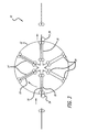
- Fig. 3 is a cross-sectional view of a duplexing device 10 designed in accordance with an illustrative embodiment of the present invention.
- the novel duplexer 10 includes a first mechanism 12 comprised of a predetermined number of slots 14, each slot 14 adapted to receive and hold a media sheet 16.
- the mechanism 12 is shaped like a "wagon wheel", with each slot 14 oriented along a radius of the wheel 12.
- the mechanism 12 is adapted to rotate about an axis that lies in the plane of the media sheet 16 and is perpendicular to the paper transport direction (parallel to a transverse axis of the sheet).
- Fig. 3 is a cross-sectional view of a duplexing device 10 designed in accordance with an illustrative embodiment of the present invention.
- the novel duplexer 10 includes a first mechanism 12 comprised of a predetermined number of slots 14, each slot 14 adapted to receive and hold a media sheet 16.
- the mechanism 12 is shaped like a "wagon wheel", with each
- the duplexer 10 also includes a mechanism for rotating the wheel 12.
- a controller 120 operates through a drive motor 118 (shown in Figs. 1 and 2) to cause the wheel 12 to be selectively rotated.
- Inversion of a media sheet 16 is accomplished by receiving a sheet 16 into a slot at an input position 18, rotating the mechanism 12 until the slot is in an output position 20, and outputting the sheet 16 at the output position 20. Manipulation of a sheet in this fashion results in the former trailing edge of the sheet becoming the new leading edge.
- the sheet 16 enters from the left into a slot oriented in the nine o'clock position, and exits to the right from the same slot, but oriented in the three o'clock position.
- Other input and output locations may be chosen without departing from the scope of the present invention. The input and output locations do not necessarily need to be on opposite sides.
- the duplexer 10 is shown with six slots 14.
- the invention is not limited to the number of slots 14 in the rotating mechanism 12.
- the mechanism 12 can have two, or more slots 14 without departing from the scope of the present teachings.
- the mechanism 12 may have a significantly larger number of slots, the number of slots being limited only by potential interference of the components of adjacent slots.
- one media sheet can enter a slot at the input position 18, while another sheet simultaneously exits from a slot at the output position 20. If the mechanism 12 has more than two slots, a slot does not rotate immediately from the input position 18 to the output position 20. It stops at one or more intermediate positions. For example, in the illustrative embodiment of Fig. 3 (which has six slots 14), after a first media sheet enters a first slot at the input position 18 (nine o'clock), the wheel 12 rotates to orient the next slot at the input position 18. The first media sheet remains in the first slot which is now at the first intermediate position 22 (eleven o'clock in the example), and the next media sheet enters the slot which is now at the input position 18. The wheel 12 continues to rotate in this fashion, stopping at each indexing point to allow a sheet to enter at the input position 18 and a sheet to exit at the output position 20. Media sheets thus have time to dry while they are in the intermediate positions between the input and output positions.
- This method allows the gap between media sheets to be much smaller than the length of a sheet (as is required by prior art methods).
- the gap between sheets is determined by the time needed to rotate from one position to the next.
- An additional advantage is that dry time can be provided to whatever extent is desired (up to a certain limit) by increasing the number of slots in the mechanism 12. The larger the number of slots, the smaller the angular travel necessary between sheets (reducing the head-to-tail distance between pages and increasing throughput), and the longer dry time offered to each sheet (due to the greater number of cycles between entering the duplexer and exiting the duplexer).
- the slots 14 may include nip rollers 24 for inputting and outputting sheets 16, and holding sheets 16 in place.
- nip rollers 24 should be powered at the input and output positions, but stationary at all other points (to hold the media in place during rotation of the wagon wheel 12).
- the rotational power of these rollers 24 can be provided in a number of ways including (but not limited to) a friction drive wheel 26 (which does not rotate with the wagon wheel 12) which engages with one of the nip rollers 24 of a slot oriented at the input position 18, and another friction drive wheel 28 which does the same at the output position 20.
- the motion of these motors (and rollers), as well as the rotation of the wagon wheel, should be carefully controlled to start and stop as needed.
- Each slot should be at least as long as the longest media type required.
- the number of slots determines the angular rotation of the wheel for each cycle.
- the duplexer 10 may optionally include an operational mode for simplex printing.
- the wheel 12 remains stationary, and internal nip rollers 24 guide sheets straight through the mechanism 12 from the input position 18 to the output position 20.
- This embodiment requires a clear path from the input slot to the output slot (i.e. a hollow center).
- An edge sensor (not shown) can be employed upstream of the rotating mechanism 12 to provide trailing edge information, to ensure that a media sheet is properly positioned in the input slot (with the new leading edge being a predetermined distance from the nip rollers which reside in each slot).
Landscapes
- Engineering & Computer Science (AREA)
- Mechanical Engineering (AREA)
- Separation, Sorting, Adjustment, Or Bending Of Sheets To Be Conveyed (AREA)
- Registering Or Overturning Sheets (AREA)
- Handling Of Cut Paper (AREA)
- Delivering By Means Of Belts And Rollers (AREA)
Claims (8)
- Ein System (10) zum Wenden eines Medienblatts (16), das folgende Merkmale aufweist:ein Rad (12), das eine Mehrzahl von Schlitzen (14) aufweist, das angepasst ist, um das Medienblatt (16) aufzunehmen und zu halten, wobei jeder Schlitz (14) zumindest so lange wie der längste erforderliche Medientyp ist, undeinen Mechanismus (118) zum Drehen des Rads (12) um eine Achse, die in der Ebene des Medienblatts (16) liegt und senkrecht zu einer Medienblatttransportrichtung ist,wobei das Rad (12) eine hohle Mitte zum Bereitstellen eines freien Wegs zwischen einem ersten Schlitz, der an einer Eingangsposition (18) ausgerichtet ist, und einem zweiten Schlitz, der an einer Ausgangsposition (20) ausgerichtet ist, umfasst,wobei in einem ersten Betriebsmodus der Mechanismus (118) angepasst ist, um das Rad (12) zum Wenden eines Medienblatts (16) zu drehen, undwobei in einem zweiten Betriebsmodus das Rad (12) feststehend bleibt und zum Führen eines Medienblatts (16) von einem ersten Schlitz, der an der Eingangsposition (18) ausgerichtet ist, durch die hohle Mitte des Rads (12) zu einem zweiten Schlitz, der an der Ausgangsposition (20) ausgerichtet ist, angepasst ist.
- Das System gemäß Anspruch 1, bei dem das Rad (12) angepasst ist, um ein erstes Medienblatt aufzunehmen, während ein zweites Blatt abgeht.
- Das System gemäß Anspruch 1 oder 2, bei dem die Schlitze (14) entlang eines Radius des Rads (12) ausgerichtet sind.
- Das System gemäß einem der Ansprüche 1 bis 3, bei dem der Mechanismus (118) das Rad (12) derart dreht, dass eine Drehung aussetzt, wenn ein Schlitz (14) an der Eingangsposition (18) ausgerichtet ist.
- Das System gemäß einem der Ansprüche 1 bis 4, bei dem die Schlitze (14) eine Mehrzahl von Anpressrollen (24) umfassen, um die Medienblätter (16) am Platze zu halten.
- Das System gemäß Anspruch 5, das ferner einen zweiten Mechanismus (26) zum Eingeben des Medienblatts (16) mit einer vorderen Kante und einer hinteren Kante in das Rad (12) umfasst.
- Das System gemäß Anspruch 6, bei dem der zweite Mechanismus (26) ein Reibungsantriebsrad umfasst, das angepasst ist, um eine der Anpressrollen (24) eines Schlitzes, der an einer Ausgangsposition (18) ausgerichtet ist, in Eingriff zu nehmen.
- Das System gemäß Anspruch 5 oder 6, das ferner einen dritten Mechanismus (28) zum Ausgeben des Medienblatts aus dem Rad (12), wobei die hintere Kante vorne ist, umfasst.
Applications Claiming Priority (2)
| Application Number | Priority Date | Filing Date | Title |
|---|---|---|---|
| US419473 | 2003-04-21 | ||
| US10/419,473 US7420703B2 (en) | 2003-04-21 | 2003-04-21 | System and method for flipping a media sheet |
Publications (2)
| Publication Number | Publication Date |
|---|---|
| EP1471019A1 EP1471019A1 (de) | 2004-10-27 |
| EP1471019B1 true EP1471019B1 (de) | 2006-12-20 |
Family
ID=32962399
Family Applications (1)
| Application Number | Title | Priority Date | Filing Date |
|---|---|---|---|
| EP03023217A Expired - Lifetime EP1471019B1 (de) | 2003-04-21 | 2003-10-13 | System und Verfahren zum Wenden von Bögen |
Country Status (4)
| Country | Link |
|---|---|
| US (1) | US7420703B2 (de) |
| EP (1) | EP1471019B1 (de) |
| JP (1) | JP3876257B2 (de) |
| DE (1) | DE60310524D1 (de) |
Families Citing this family (5)
| Publication number | Priority date | Publication date | Assignee | Title |
|---|---|---|---|---|
| CN103387151B (zh) * | 2012-05-07 | 2015-10-14 | 浙江蓝宝机械有限公司 | 一种翻转式整理纸叠的齐纸装置 |
| DE102012021404A1 (de) * | 2012-10-30 | 2014-04-30 | Eastman Kodak Company | Bogenwendeeinheit und verfahren zum wenden eines bogens |
| DE102012021402A1 (de) * | 2012-10-30 | 2014-05-15 | Eastman Kodak Company | Bogenwendeeinheit und verfahren zum wenden eines bogens |
| DE102014006078A1 (de) * | 2014-04-25 | 2015-10-29 | Kolbus Gmbh & Co. Kg | Vorrichtung und Verfahren zum Wenden vorwiegend flächiger Produkte |
| JP7547904B2 (ja) * | 2020-04-01 | 2024-09-10 | 株式会社リコー | シート保持装置、画像形成装置、及び画像形成システム |
Citations (1)
| Publication number | Priority date | Publication date | Assignee | Title |
|---|---|---|---|---|
| US5709484A (en) * | 1995-04-24 | 1998-01-20 | Kunz Gmbh | Apparatus for double-sided printing of identification cards |
Family Cites Families (20)
| Publication number | Priority date | Publication date | Assignee | Title |
|---|---|---|---|---|
| DE558976C (de) | 1932-09-14 | Georg Keil | Aus zwei Druckwerken bestehende Schoen- und Widerdruckmaschine fuer Werkstuecke, insbesondere Bierglasuntersaetze | |
| DE32885C (de) | GANDEN-BERGER'sche MASCHINENFABRIK GEORG GÖBEL in Darmstadt | Schaufelrad zum Wenden der Billets an einer Billetdruckmaschine | ||
| DE917764C (de) | 1952-07-10 | 1954-09-09 | Waldhof Zellstoff Fab | Vorrichtung zum Wenden von Bogen, Platten od. dgl. aus Zellstoff, Papier od. dgl. |
| US4307800A (en) | 1979-12-03 | 1981-12-29 | Joa Curt G | Apparatus for alternating the folded and open edges of a succession of folded pads |
| JPS59190140A (ja) | 1983-04-12 | 1984-10-27 | Fuji Xerox Co Ltd | シ−ト状用紙の反転装置 |
| US4693464A (en) | 1984-12-20 | 1987-09-15 | Laurel Bank Machines Co., Ltd. | Apparatus for arranging the obverse and reverse sides of the bills or the like |
| JPS61188350A (ja) | 1985-02-13 | 1986-08-22 | Oki Electric Ind Co Ltd | 表裏反転機構 |
| GB2219990B (en) | 1988-06-22 | 1992-07-29 | Xerox Corp | Sheet stacking and inverting apparatus |
| JPH02215638A (ja) | 1989-02-15 | 1990-08-28 | Nec Corp | 紙葉類の先端逆転機構 |
| US5151077A (en) * | 1991-07-31 | 1992-09-29 | Ark, Inc. | Method and apparatus for perforating material |
| NL9400542A (nl) | 1994-04-06 | 1995-11-01 | Buhrs Zaandam Bv | Omkeerinrichting alsmede een werkwijze voor het omkeren van bijvoorbeeld grafische produkten. |
| JP3117894B2 (ja) | 1995-04-07 | 2000-12-18 | シャープ株式会社 | 用紙反転装置 |
| DE19527264A1 (de) * | 1995-07-26 | 1997-01-30 | Heidelberger Druckmasch Ag | Druckmaschine mit geradliniger Substratführung und Wendeeinrichtungen dafür |
| WO1999011551A1 (en) * | 1997-09-04 | 1999-03-11 | Xaar Technology Limited | Vacuum drums for printing, and duplex printers |
| IT1316314B1 (it) | 2000-01-31 | 2003-04-10 | Sitma Spa | Dispositivo di girata per prodotti grafici editoriali in una linea ditrasporto e/o confezionatrice |
| JP2001310503A (ja) | 2000-04-28 | 2001-11-06 | Canon Inc | 記録装置 |
| US6443450B1 (en) * | 2000-11-30 | 2002-09-03 | Xerox Corporation | Sheet stacking apparatus and method |
| EP1234791B1 (de) | 2001-02-19 | 2004-10-06 | Grapha-Holding AG | Vorrichtung für die Übernahme und Weitergabe von Druckprodukten |
| DE10116481A1 (de) | 2001-04-03 | 2002-10-10 | Hans Walter Mohr Gmbh | Vorrichtung zum Wenden |
| US6976673B2 (en) * | 2003-04-21 | 2005-12-20 | Hewlett-Packard Development Company, L.P. | System and method for flipping a media sheet |
-
2003
- 2003-04-21 US US10/419,473 patent/US7420703B2/en not_active Expired - Fee Related
- 2003-10-13 DE DE60310524T patent/DE60310524D1/de not_active Expired - Lifetime
- 2003-10-13 EP EP03023217A patent/EP1471019B1/de not_active Expired - Lifetime
-
2004
- 2004-04-15 JP JP2004120243A patent/JP3876257B2/ja not_active Expired - Fee Related
Patent Citations (1)
| Publication number | Priority date | Publication date | Assignee | Title |
|---|---|---|---|---|
| US5709484A (en) * | 1995-04-24 | 1998-01-20 | Kunz Gmbh | Apparatus for double-sided printing of identification cards |
Also Published As
| Publication number | Publication date |
|---|---|
| US20040208679A1 (en) | 2004-10-21 |
| JP3876257B2 (ja) | 2007-01-31 |
| DE60310524D1 (de) | 2007-02-01 |
| JP2004323239A (ja) | 2004-11-18 |
| US7420703B2 (en) | 2008-09-02 |
| EP1471019A1 (de) | 2004-10-27 |
Similar Documents
| Publication | Publication Date | Title |
|---|---|---|
| US7421241B2 (en) | Printing system with inverter disposed for media velocity buffering and registration | |
| US6782236B2 (en) | Duplex image forming apparatus | |
| US4579446A (en) | Both-side recording system | |
| US7416185B2 (en) | Inverter with return/bypass paper path | |
| US20060214364A1 (en) | Sheet registration within a media inverter | |
| JP4542994B2 (ja) | 用紙搬送装置及び画像形成装置 | |
| JP4193925B2 (ja) | 画像形成システム | |
| EP1471019B1 (de) | System und Verfahren zum Wenden von Bögen | |
| JP2004345769A (ja) | 用紙処理装置 | |
| US9108820B2 (en) | Sheet folding apparatus and image forming apparatus | |
| US6976673B2 (en) | System and method for flipping a media sheet | |
| JPH0635265A (ja) | 画像形成装置の両面ユニット | |
| US6042528A (en) | Apparatus for buffering, turning over, folding and orientating forms | |
| EP1968296B1 (de) | Verfahren für den Duplexdruck auf Blattmedien | |
| KR101273226B1 (ko) | 매체 수송 시스템 | |
| JP2019137517A (ja) | 画像形成装置 | |
| US8708337B2 (en) | Dual flip over roll inverter | |
| JPH1111771A (ja) | プリンタの用紙反転装置 | |
| JP2004050686A (ja) | プリンタ | |
| KR970010135A (ko) | 잉크제트 프린터의 양면인쇄장치 및 그 방법 | |
| JPS61150950A (ja) | シ−ト反転機構 | |
| JP2002154718A (ja) | 画像形成装置 | |
| JPH06255857A (ja) | 印字機の排紙装置 | |
| JPH1196310A (ja) | カード処理装置 | |
| JPH0412978A (ja) | 両面画像形成装置 |
Legal Events
| Date | Code | Title | Description |
|---|---|---|---|
| PUAI | Public reference made under article 153(3) epc to a published international application that has entered the european phase |
Free format text: ORIGINAL CODE: 0009012 |
|
| AK | Designated contracting states |
Kind code of ref document: A1 Designated state(s): AT BE BG CH CY CZ DE DK EE ES FI FR GB GR HU IE IT LI LU MC NL PT RO SE SI SK TR |
|
| AX | Request for extension of the european patent |
Extension state: AL LT LV MK |
|
| 17P | Request for examination filed |
Effective date: 20050210 |
|
| AKX | Designation fees paid |
Designated state(s): DE FR GB |
|
| GRAP | Despatch of communication of intention to grant a patent |
Free format text: ORIGINAL CODE: EPIDOSNIGR1 |
|
| GRAC | Information related to communication of intention to grant a patent modified |
Free format text: ORIGINAL CODE: EPIDOSCIGR1 |
|
| GRAS | Grant fee paid |
Free format text: ORIGINAL CODE: EPIDOSNIGR3 |
|
| GRAA | (expected) grant |
Free format text: ORIGINAL CODE: 0009210 |
|
| AK | Designated contracting states |
Kind code of ref document: B1 Designated state(s): DE FR GB |
|
| REG | Reference to a national code |
Ref country code: GB Ref legal event code: FG4D |
|
| REF | Corresponds to: |
Ref document number: 60310524 Country of ref document: DE Date of ref document: 20070201 Kind code of ref document: P |
|
| PG25 | Lapsed in a contracting state [announced via postgrant information from national office to epo] |
Ref country code: DE Free format text: LAPSE BECAUSE OF FAILURE TO SUBMIT A TRANSLATION OF THE DESCRIPTION OR TO PAY THE FEE WITHIN THE PRESCRIBED TIME-LIMIT Effective date: 20070321 |
|
| EN | Fr: translation not filed | ||
| PLBE | No opposition filed within time limit |
Free format text: ORIGINAL CODE: 0009261 |
|
| STAA | Information on the status of an ep patent application or granted ep patent |
Free format text: STATUS: NO OPPOSITION FILED WITHIN TIME LIMIT |
|
| 26N | No opposition filed |
Effective date: 20070921 |
|
| PG25 | Lapsed in a contracting state [announced via postgrant information from national office to epo] |
Ref country code: FR Free format text: LAPSE BECAUSE OF FAILURE TO SUBMIT A TRANSLATION OF THE DESCRIPTION OR TO PAY THE FEE WITHIN THE PRESCRIBED TIME-LIMIT Effective date: 20070810 |
|
| PG25 | Lapsed in a contracting state [announced via postgrant information from national office to epo] |
Ref country code: FR Free format text: LAPSE BECAUSE OF FAILURE TO SUBMIT A TRANSLATION OF THE DESCRIPTION OR TO PAY THE FEE WITHIN THE PRESCRIBED TIME-LIMIT Effective date: 20061220 |
|
| PGFP | Annual fee paid to national office [announced via postgrant information from national office to epo] |
Ref country code: GB Payment date: 20180925 Year of fee payment: 16 |
|
| GBPC | Gb: european patent ceased through non-payment of renewal fee |
Effective date: 20191013 |
|
| PG25 | Lapsed in a contracting state [announced via postgrant information from national office to epo] |
Ref country code: GB Free format text: LAPSE BECAUSE OF NON-PAYMENT OF DUE FEES Effective date: 20191013 |