EP1469366B1 - Ventil für Heizungsanlagen - Google Patents
Ventil für Heizungsanlagen Download PDFInfo
- Publication number
- EP1469366B1 EP1469366B1 EP04002639A EP04002639A EP1469366B1 EP 1469366 B1 EP1469366 B1 EP 1469366B1 EP 04002639 A EP04002639 A EP 04002639A EP 04002639 A EP04002639 A EP 04002639A EP 1469366 B1 EP1469366 B1 EP 1469366B1
- Authority
- EP
- European Patent Office
- Prior art keywords
- valve
- temperature sensor
- valve according
- room temperature
- adjusting
- Prior art date
- Legal status (The legal status is an assumption and is not a legal conclusion. Google has not performed a legal analysis and makes no representation as to the accuracy of the status listed.)
- Expired - Lifetime
Links
- 238000010438 heat treatment Methods 0.000 title claims description 14
- 238000006073 displacement reaction Methods 0.000 claims description 8
- 230000005540 biological transmission Effects 0.000 claims description 5
- 239000011295 pitch Substances 0.000 claims description 3
- 230000000712 assembly Effects 0.000 claims 1
- 238000000429 assembly Methods 0.000 claims 1
- 239000000463 material Substances 0.000 claims 1
- 229920003023 plastic Polymers 0.000 claims 1
- 239000004033 plastic Substances 0.000 claims 1
- 230000000717 retained effect Effects 0.000 claims 1
- 239000012530 fluid Substances 0.000 description 4
- 210000004907 gland Anatomy 0.000 description 2
- 230000001276 controlling effect Effects 0.000 description 1
- 238000001816 cooling Methods 0.000 description 1
- 230000008878 coupling Effects 0.000 description 1
- 238000010168 coupling process Methods 0.000 description 1
- 238000005859 coupling reaction Methods 0.000 description 1
- 230000001419 dependent effect Effects 0.000 description 1
- 239000008236 heating water Substances 0.000 description 1
- 230000013011 mating Effects 0.000 description 1
- 230000001105 regulatory effect Effects 0.000 description 1
- 238000007789 sealing Methods 0.000 description 1
- XLYOFNOQVPJJNP-UHFFFAOYSA-N water Substances O XLYOFNOQVPJJNP-UHFFFAOYSA-N 0.000 description 1
Images


Classifications
-
- G—PHYSICS
- G05—CONTROLLING; REGULATING
- G05D—SYSTEMS FOR CONTROLLING OR REGULATING NON-ELECTRIC VARIABLES
- G05D23/00—Control of temperature
- G05D23/01—Control of temperature without auxiliary power
- G05D23/02—Control of temperature without auxiliary power with sensing element expanding and contracting in response to changes of temperature
- G05D23/021—Control of temperature without auxiliary power with sensing element expanding and contracting in response to changes of temperature the sensing element being a non-metallic solid, e.g. elastomer, paste
- G05D23/023—Control of temperature without auxiliary power with sensing element expanding and contracting in response to changes of temperature the sensing element being a non-metallic solid, e.g. elastomer, paste the sensing element being placed outside a regulating fluid flow
Definitions
- the invention relates to a valve according to the preamble of claim 1.
- a valve of the type assumed to be known (DE 202 03 735 U1) with a combined sensor head already enables an independent adjustment of the room temperature sensor and the return temperature sensor.
- the return temperature sensor is set by a collar during assembly to a predetermined for the regulated heating circuit compatible water temperature.
- the collar is often no longer easily accessible to a user and not suitable for the adjustment of the return temperature by a user.
- the room temperature is only changed at the room temperature sensor.
- Such a valve has the disadvantage that the controllable room temperature range is restricted. For example, in extreme weather conditions, in which the room temperature sensor is set to the highest temperature level, the corresponding room temperature can not be achieved because the return temperature for it is too low.
- the invention has for its object to improve the operation of a valve with Kombifühlerkopf and to increase its scope.
- the adjusting sleeve can be provided with the adjustment facilitating hints and adjustment marks.
- the adjustment of the room temperature sensor may be coupled to that of the return temperature sensor. This eliminates the need for the user, the separate operation of the return temperature sensor without the area of use of the valve is reduced.
- Such a coupling can be achieved by fixed connection of the adjusting elements, wherein different strokes is made possible by different thread pitches of the Huaweiverstellium in a simple manner.
- the valve may be designed to be pivotable or have different connecting pieces, so that it can be used in different mounting positions. With corresponding fittings, it is also possible to control several heating circuits simultaneously with such a valve.
- a valve for controlling heating systems has a combined sensor head comprising a room temperature sensor 2 and a return temperature sensor 3 in a coaxial arrangement.
- the combined sensor head is fixed to a valve housing 1 which is pivotally received on one side in an inlet fitting 4 and on the other side in an outlet fitting 5.
- two heating circuits may be connected in inlet bores 4a and at the outlet fitting 5 in outlet bores 5a.
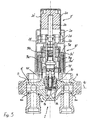
- the room temperature sensor 2 is accommodated essentially in an adjusting cap 2c rotatable about its longitudinal axis and the return temperature sensor 3 in a setting sleeve 3d rotatable relative thereto.
- the room temperature sensor 2 is of generally known type and therefore not shown here in detail. It has an expanding body 2a, which acts on a pressure member 2b.
- the room temperature sensor 2 is screwed onto a thread 2d on the return temperature sensor 3 with a counter thread 2e provided on its adjusting cap 2c.
- the return temperature sensor 3 also has a DehnMech 3a, which extends coaxially with the pressure member 2b and is supported on an abutment 3b, which is held by means of a threaded connection 3e in a collar 3c.
- the abutment 3b is prevented from rotating.
- the outer periphery of the adjusting ring 3c is connected to the adjusting sleeve 3d. A rotation of the adjusting sleeve 3d therefore leads to a displacement of the abutment 3b and the supporting thereon strain body 3a in the direction of the axis of rotation of the adjusting sleeve 3d.
- the abutment 3b is penetrated by a slotted transmission member 2g, at one end of the pressure member 2b engages a compensating spring 2f.
- the other end of the transmission member 2g is supported on the expansion body 3a.
- the Kombifühlerkopf is attached by means of a threaded ring 3f to a connecting piece 1d of the valve housing 1.
- valve stem 1b At the end remote from the abutment 3b end of the expansion body 3a is located on a valve stem 1b, which carries a valve plate 1a.
- the valve stem 1b is received in a gland 1h, which is screwed into the valve housing 1 and closes a valve chamber 1i.
- the valve stem 1b and the valve plate 1a are biased against the reverse direction of the valve with a return spring 1e.
- a heat-conducting element 1k is screwed in, which partially encloses the expansion body 3a. In this way, the temperature of the through-hole 1g supplied or discharged heating fluid is transferred to the expansion body 3a.
- the pressure member 2b Upon rotation of the room temperature sensor 2 to lower room temperatures, the pressure member 2b is moved in the direction of the valve housing 1.
- the compensation spring 2f is the transmission member 2g entrained, as long as the valve disk 1a has not reached its closed position. If the valve is already closed, only the compensating spring 2f is compressed.
- the transmission member 2g displaces the expansion body 3a, which transmits its displacement to the valve stem 1b, so that the flow area of the valve chamber 1i is reduced.
- the return spring 1e is tensioned.
- An increase in the room temperature acts by the expansion of the expansion body 2a in the same way.
- the return temperature of the heating fluid can be adjusted by turning the adjusting sleeve 3d.
- the rotation of the adjusting ring 3c causes a displacement of the abutment 3b, so that the valve disk 1a is displaced in one direction over the expansion body 3a abutting on the valve stem 1b or in the opposite direction by the return spring 1e.
- the heating fluid exceeds the set value, the expanding body 3a expands and closes the valve.
- the valve stem 1b is held in abutment with the expansion body 3a by the return spring 1e, so that the valve opens again.
- the adjusting cap 2c 'of the room temperature sensor 2' is made integral with the adjusting sleeve 3d 'of the return temperature sensor 3', so that rotation can only take place together.
- the adjusting cap 2c ' is rotatably supported by a thread 2d as in the first embodiment, in which it engages with a mating thread 2e.
- the thread 2d is on a on the adjusting ring 3c 'supporting support ring 2h intended. Upon rotation of the adjusting cap 2c ', this shifts together with the adjusting sleeve 3d' in its axial direction.
- a displacement of the adjusting sleeve 3d 'relative to the non-displaceable adjusting ring 3c' is made possible by a toothing provided on its outer circumference, which engages in an internal toothing 3g on the adjusting sleeve 3d '.
- the adjusting sleeve 3d takes with its rotation the adjusting ring 3c', so that the abutment 3b can adjust in the axial direction via the threaded connection 3e.
- the degree of adjustment depends on the thread pitch, so that a different size adjustment of pressure member 2b and 3 stretch body can be selected. Otherwise, the valve in the embodiment of FIG. 3 corresponds to the embodiment in FIG. 2 and will not be described again here.
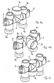
- Fig. 4a to 4c the valve housing 1 is shown with the fittings 4 and 5 in different pivotal positions of the connecting piece 1a.
- the position of the connecting piece 1a in Fig. 4a corresponds to the illustrations in Fig. 1 and 2.
- the axes of rotation of room temperature sensor 2 and return temperature sensor 3 and the axes of the inlet and outlet holes 4a and 5a lie in a plane.
- the heating fluid is supplied, for example, through the inlet bore 4a, flows through the valve housing 1 in an approximately horizontal direction and exits from the outlet hole 5a, wherein it enters and exits through the through holes 1g in the valve housing 1.
- the through holes 1f are closed by the connecting pieces 4 and 5.
- the valve housing 1 shown in Fig. 4b is compared with the connecting pieces 4 and 5 swung out by 90 ° from the plane of the drawing. In this position, the through holes 1f are aligned with the inlet and outlet holes 4a and 5a. The through holes 1g are closed by the connecting pieces 4 and 5. Upon rotation of the valve housing 1 about the pivot axis 1c by 180 °, as shown in Fig. 4c, all through-holes 1f and 1g are closed. In this position, for example, assembly work on the heating system can be made without the heating water must be completely drained.
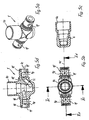
- the mounting of the valve housing 1 in the inlet and outlet Rantücken 4 and 5 are designed as rotary feedthroughs 6.
- the rotary feedthroughs 6 are, as shown in Fig. 5a to 5d, formed by two concentric with the pivot axis 1c extending annular grooves 11, are inserted in the sealing rings 1m.
Landscapes
- Physics & Mathematics (AREA)
- Fluid Mechanics (AREA)
- General Physics & Mathematics (AREA)
- Engineering & Computer Science (AREA)
- Automation & Control Theory (AREA)
- Temperature-Responsive Valves (AREA)
- Details Of Valves (AREA)
- Indication Of The Valve Opening Or Closing Status (AREA)
- Heat-Pump Type And Storage Water Heaters (AREA)
Description
- Die Erfindung betrifft ein Ventil nach dem Oberbegriff des Anspruchs 1.
- Ein Ventil der als bekannt vorausgesetzten Art (DE 202 03 735 U1) mit einem Kombifühlerkopf ermöglicht bereits eine unabhängige Einstellung von Raumtemperaturfühler und Rücklauftemperaturfühler. Der Rücklauftemperaturfühler wird durch einen Stellring bei der Montage auf eine vorgegebene für den geregelten Heizkreislauf verträgliche Wassertemperatur eingestellt. Der Stellring ist für einen Benutzer häufig nicht mehr ohne weiteres zugänglich und für die Verstellung der Rücklauftemperatur durch einen Benutzer nicht geeignet. Die Raumtemperatur wird jeweils ausschließlich am Raumtemperaturfühler verändert. Ein derartiges Ventil hat den Nachteil, daß der regelbare Raumtemperaturbereich eingeschränkt wird. Beispielsweise kann bei extremen Witterungsverhältnissen, bei denen der Raumtemperaturfühler auf die höchste Temperaturstufe eingestellt wird, die entsprechende Raumtemperatur nicht erreicht werden, weil die Rücklauftemperatur dafür zu niedrig ist.
- Der Erfindung liegt die Aufgabe zugrunde, die Bedienung eines Ventils mit Kombifühlerkopf zu verbessern und dessen Einsatzbereich zu vergrößern.
- Die Aufgabe wird durch die Merkmale des Patentanspruchs 1 gelöst.
- Durch die Einstellhülse kann die Rücklauftemperatur von einem Benutzer auf einfache Weise eingestellt werden. Dadurch vergrößert sich der verstellbare Temperaturbereich des Ventils und die Raumtemperatur lässt sich gegebenenfalls schneller erreichen. Die Einstellhülse kann mit die Einstellung erleichternden Hinweisen und Einstellzeichen versehen sein.
- In einer besonders vorteilhaften Ausführung des Ventils kann die Verstellung des Raumtemperaturfühlers mit der des Rücklauftemperaturfühlers gekoppelt sein. Dadurch entfällt für den Benutzer die separate Betätigung des Rücklauftemperaturfühlers, ohne dass der Einsatzbereich des Ventils verkleinert wird. Eine derartige Kopplung kann durch feste Verbindung der Einstellelemente erreicht werden, wobei unterschiedliche Stellhübe durch unterschiedliche Gewindesteigungen der Fühlerverstellelemente auf einfache Weise ermöglicht wird.
- In weitere Ausgestaltung der Erfindung kann das Ventil schwenkbar ausgebildet sein oder unterschiedliche Anschlussstutzen aufweisen, so dass es in unterschiedlichen Einbaulagen verwendet werden kann. Mit entsprechenden Anschlussstücken lassen sich mit einem solchen Ventil auch mehrere Heizkreise gleichzeitig regeln.
- Weitere vorteilhafte Ausgestaltungen der Erfindung ergeben sich aus den Unteransprüchen.
- Im folgenden werden zwei Ausführungsbeispiele der Erfindung anhand der Zeichnungen näher erläutert. Es zeigen:
- Figur 1 -
- eine perspektivische Ansicht eines zwischen Anschlussstücken angeordneten Ventils mit einem Kombifühlerkopf;
- Figur 2 -
- einen Schnitt entlang der Mittenebene des Ventils in einer ersten Ausführungsform mit in die Mittenebene geschwenktem Kombifühlerkopf nach Fig. 1;
- Figur 3 -
- einen Schnitt gemäß Fig. 2 durch ein Ventil in einer zweiten Ausführungsform;
- Figur 4a -
- eine perspektivische Ansicht des Ventilkörpers mit Ein- und Auslassstücken gemäß Fig. 2 und 3;
- Figur 4b -
- eine perspektivische Ansicht des Ventilkörpers mit Ein- und Auslassstücken gemäß Fig. 4a mit nach vorn geklapptem Anschlussstutzen gemäß Fig. 1;
- Figur 4c -
- eine perspektivische Ansicht des Ventilkörpers mit Ein- und Auslassstücken gemäß Figur 4a mit dem Anschlussstutzen in Absperrstellung;
- Figur 5a -
- eine perspektivische Ansicht des Ventilkörpers nach Fig. 4a;
- Figur 5b -
- eine Draufsicht auf den Ventilkörper nach Fig. 5a;
- Figur 5c -
- einen Schnitt durch den Ventilköper entlang der Schnittebene Vc - Vc in Fig. 5b;
- Figur 5d -
- einen Schnitt durch den Ventilkörper entlang der Schnittebene Vd - Vd in Fig. 5b.
- In den Zeichnungen sind gleiche Teile mit gleichen Bezugszeichen versehen, die sich im Bedarfsfall durch Hochstriche voneinander unterscheiden.
- Ein Ventil zur Regelung von Heizungsanlagen weist einen Kombifühlerkopf auf, der einen Raumtemperaturfühler 2 und einen Rücklauftemperaturfühler 3 in koaxialer Anordnung umfasst. Der Kombifühlerkopf ist an einem Ventilgehäuse 1 befestigt, das schwenkbar auf einer Seite in einem Einlass-Anschlussstück 4 und auf der anderen Seite in einem Auslass-Anschlussstück 5 aufgenommen ist. An dem Einlass-Anschlussstück 4 können zwei Heizkreise in Einlassbohrungen 4a und an dem Auslass-Anschlussstück 5 in Auslassbohrungen 5a angeschlossen werden.
- Bei einer ersten Ausführungsform des Ventils gemäß Fig. 2 ist der Raumtemperaturfühler 2 im wesentlichen in einer um seine Längsachse drehbaren Einstellkappe 2c und der Rücklauftemperaturfühler 3 in einer demgegenüber drehbaren Einstellhülse 3d untergebracht. Der Raumtemperaturfühler 2 ist von allgemein bekannter Bauart und daher hier nicht im einzelnen dargestellt. Er weist einen Dehnkörper 2a auf, der ein Druckglied 2b beaufschlagt. Der Raumtemperaturfühler 2 ist mit einem an seiner Einstellkappe 2c vorgesehenen Gegengewinde 2e auf ein Gewinde 2d am Rücklauftemperaturfühler 3 aufgeschraubt.
- Der Rücklauftemperaturfühler 3 besitzt ebenfalls einen Dehnkörper 3a, der sich koaxial zu dem Druckglied 2b erstreckt und sich an einem Widerlager 3b abstützt, das mittels einer Gewindeverbindung 3e in einem Stellring 3c gehalten wird. Das Widerlager 3b ist an einer Drehung gehindert. Der Außenumfang des Stellrings 3c ist mit der Einstellhülse 3d verbunden. Eine Drehung der Stellhülse 3d führt daher zu einer Verlagerung des Widerlagers 3b und des sich daran abstützenden Dehnkörpers 3a in Richtung der Drehachse der Einstellhülse 3d. Das Widerlager 3b wird von einem geschlitzten Übertragungsglied 2g durchsetzt, an dessen einen Ende das Druckglied 2b über eine Ausgleichsfeder 2f angreift. Das andere Ende des Übertragungsgliedes 2g stützt sich an dem Dehnkörper 3a ab. Der Kombifühlerkopf ist mittels eines Gewinderings 3f an einem Anschlussstutzen 1d des Ventilgehäuses 1 befestigt.
- An dem vom Widerlager 3b abgewandten Ende des Dehnkörpers 3a liegt ein Ventilschaft 1b an, der einen Ventilteller 1a trägt. Der Ventilschaft 1b ist in einer Stopfbuchse 1h aufgenommen, die in das Ventilgehäuse 1 eingeschraubt ist und eine Ventilkammer 1i verschließt. Der Ventilschaft 1b und der Ventilteller 1a sind mit einer Rückstellfeder 1e entgegen der Sperrrichtung des Ventils vorgespannt. In die Stopfbuchse 1h ist ein Wärmeleitelement 1k eingeschraubt, das den Dehnkörper 3a teilweise umschließt. Auf diese Weise wird die Temperatur der durch eine Durchgangsbohrung 1g zu- bzw. abgeführten Heizflüssigkeit auf den Dehnkörper 3a übertragen.
- Bei einer Drehung des Raumtemperaturfühlers 2 zu niedrigeren Raumtemperaturen wird das Druckglied 2b in Richtung des Ventilgehäuses 1 verschoben. Über die Ausgleichsfeder 2f wird das Übertragungsglied 2g mitgenommen, solange der Ventilteller 1a seine Schließstellung nicht erreicht hat. Ist das Ventil bereits geschlossen, so wird lediglich die Ausgleichsfeder 2f zusammengedrückt. Das Übertragungsglied 2g verschiebt den Dehnkörper 3a, der seine Verlagerung auf den Ventilschaft 1b überträgt, so dass der Durchflussquerschnitt der Ventilkammer 1i verringert wird. Dabei wird die Rückstellfeder 1e gespannt. Eine Erhöhung der Raumtemperatur wirkt durch die Ausdehnung des Dehnkörpers 2a in gleicher Weise.
- Die Rücklauftemperatur der Heizflüssigkeit kann durch verdrehen der Einstellhülse 3d eingestellt werden. Die Drehung des Stellrings 3c bewirkt eine Verlagerung des Widerlagers 3b, so dass der Ventilteller 1a in der einen Richtung über den am Ventilschaft 1b anliegenden Dehnkörper 3a oder in der Gegenrichtung durch die Rückstellfeder 1e verlagert wird. Wenn die Heizflüssigkeit den eingestellten Wert überschreitet, dehnt sich der Dehnkörper 3a aus und schließt das Ventil. Während der Abkühlung des Dehnkörpers 3a wird der Ventilschaft 1b durch die Rückstellfeder 1e an dem Dehnkörper 3a anliegend gehalten, so dass das Ventil wieder öffnet.
- Bei einer zweiten in Fig. 3 dargestellten Ausführungsform des Ventils ist die Einstellkappe 2c' des Raumtemperaturfühlers 2' einstückig mit der Einstellhülse 3d' des Rücklauftemperaturfühlers 3' ausgeführt, so dass eine Drehung nur gemeinsam erfolgen kann. Die Einstellkappe 2c' ist wie beim ersten Ausführungsbeispiel drehbar von einem Gewinde 2d gehalten, in das sie mit einem Gegengewinde 2e eingreift. Das Gewinde 2d ist an einem am Stellring 3c' sich abstützenden Stützring 2h vorgesehen. Bei einer Drehung der Einstellkappe 2c' verschiebt sich diese gemeinsam mit der Einstellhülse 3d' in ihrer Achsrichtung. Eine Verschiebung der Einstellhülse 3d' gegenüber dem unverschieblichen Stellring 3c' wird durch eine auf seinem Außenumfang vorgesehene Verzahnung ermöglicht, die in eine Innenverzahnung 3g an der Einstellhülse 3d' eingreift.
- Die Einstellhülse 3d' nimmt bei ihrer Drehung den Stellring 3c' mit, so dass sich das Widerlager 3b über die Gewindeverbindung 3e in Achsrichtung verstellen kann. Das Maß der Verstellung hängt dabei von der Gewindesteigung ab, so dass eine unterschiedlich große Verstellung von Druckglied 2b und Dehnkörper 3a gewählt werden kann. Im übrigen entspricht das Ventil in der Ausführung der Fig. 3 dem der Ausführung in Fig. 2 und soll hier nicht nochmals beschrieben werden.
- In Fig. 4a bis 4c ist das Ventilgehäuse 1 mit den Anschlussstücken 4 und 5 in unterschiedlichen Schwenkstellungen des Anschlussstutzens 1a dargestellt. Die Stellung des Anschlussstutzens 1a in Fig. 4a entspricht den Darstellungen in Fig. 1 und 2. Die Drehachsen von Raumtemperaturfühler 2 und Rücklauftemperaturfühler 3 sowie die Achsen der Ein- und Auslassbohrungen 4a und 5a liegen in einer Ebene. Dabei wird die Heizflüssigkeit beispielsweise durch die Einlassbohrung 4a zugeführt, durchströmt das Ventilgehäuse 1 in etwa horizontaler Richtung und tritt aus der Auslassbohrung 5a aus, wobei sie durch die Durchgangsbohrungen 1g in das Ventilgehäuse 1 einund austritt. Die Durchgangsbohrungen 1f sind durch die Anschlussstücke 4 und 5 verschlossen.
- Das in Fig. 4b dargestellte Ventilgehäuse 1 ist gegenüber den Anschlussstücken 4 und 5 um 90° aus der Zeichnungsebene herausgeschwenkt. In dieser Stellung fluchten die Durchgangsbohrungen 1f mit den Ein- und Auslassbohrungen 4a und 5a. Die Durchgangsbohrungen 1g sind durch die Anschlussstücke 4 und 5 verschlossen. Bei einer Drehung des Ventilgehäuses 1 um die Schwenkachse 1c um 180° sind, wie in Fig. 4c gezeigt, alle Durchgangsbohrungen 1f und 1g verschlossen. In dieser Stellung können beispielsweise Montagearbeiten an der Heizungsanlage vorgenommen werden, ohne dass das Heizwasser vollständig abgelassen werden muss.
- Die Lagerung des Ventilgehäuses 1 in den Einlass- und Auslass-Anschlusstücken 4 und 5 sind als Drehdurchführungen 6 ausgebildet. Die Drehdurchführungen 6 sind, wie aus Fig. 5a bis 5d ersichtlich, durch jeweils zwei konzentrisch zur Schwenkachse 1c verlaufende Ringnuten 11 gebildet, in die Dichtringe 1m eingelegt sind. Bei vollständig quer zur Schwenkachse 1c durch das Ventilgehäuse 1 hindurchführenden Durchgangsbohrungen 1f können gleichzeitig zwei an einander gegenüberliegende Einlassbohrungen 4a und Auslassbohrungen 5a angeschlossene Heizkreise mit dem Ventil geregelt werden.
Claims (15)
- Ventil für Heizungsanlagen, insbes. Fussbodenheizungen, mit einem Kombifühlerkopf (2, 3; 2', 3'), der einen Raumtemperaturfilhler (2; 2') und einen Rücklauftemperaturfühler (3; 3') umfasst, deren Dehnkörper (2a, 3a) unabhängig voneinander auf einen gemeinsamen, verschieblich im Ventilgehäuse (1) geführten Ventilschaft (1b) einwirken, wobei der Dehnkörper (3a) des Rücklauftemperaturfühlers (3; 3') sich an einem Widerlager (3b) abstützt, das mittels eines Stellrings (3c; 3c') in Achsrichtung des Ventilschaftes (1b) einstellbar ist, und ein auf den Ventilschaft (1b) wirkendes Druckglied (2b) des Raumtemperaturfühlers (2; 2') durch die Drehung der Einstellkappe (2c; 2c') des Raumtemperaturfühlers (2; 2') in Achsrichtung verstellbar ist, wobei das Druckglied (2b) koaxial zum Dehnkörper (3a) des Rücklauftemperaturfühlers (3) und koaxial zum Ventilschaft (1b) angeordnet ist,
dadurch gekennzeichnet,
dass der Stellring (3c; 3c') mit einer Einstellhülse (3d; 3d') in Eingriff steht, deren Drehung die Verlagerung des Widerlagers (3b) in Achsrichtung des Ventilschaftes (1b) bewirkt. - Ventil nach Anspruch 1,
dadurch gekennzeichnet,
dass die axiale Verlagerung des undrehbar gehaltenen Widerlagers (3b) durch eine Gewindeverbindung (3e) zwischen unverschieblichem Stellring (3c; 3c') und Widerlager (3b) bewirkt wird und die Verlagerung des Druckgliedes (2b) durch ein am Stellring (3c; 3c') sich abstützendes Gewinde (2d), in das der Raumtemperaturfühler (2; 2') mit einem Gegengewinde (2e) eingreift. - Ventil nach Anspruch 1 oder 2
dadurch gekennzeichnet,
dass die Einstellkappe (2c) des Raumtemperaturfühlers (2) an der Einstellhülse (3d) drehbar geführt und gegenüber dieser verlagerbar ist. - Ventil nach Anspruch 1 oder 2
dadurch gekennzeichnet,
dass die Einstellhülse (3d') mit der Einstellkappe (2c') undrehbar verbunden ist und gegenüber dem Stellring (3c') eine axiale Verschiebung zulässt. - Ventil nach mindestens einem der Ansprüche1, 2 oder 4,
dadurch gekennzeichnet,
dass die Einstellkappe (2c') und die Einstellhülse (3d') als einheitliches Kunststoff-Spritzgussteil herstellbar ist. - Ventil nach mindestens einem der Ansprüche 1 ,2, 4 oder 5,
dadurch gekennzeichnet,
dass die Verstellung des Widerlagers (3b) zwangsläufig proportional zur Verstellung des Druckgliedes (2b) erfolgt. - Ventil nach Anspruch 6,
dadurch gekennzeichnet,
dass die Gewindeverbindung (3e) zwischen Stellring (3c') und Widerlager (3b) und das Gewinde (2d) am Raumtemperaturfühler (2') unterschiedliche Steigungen aufweisen, deren Unterschied der Proportionalität der verstellung von Widerlager (3b) und Druckglied (2b) entspricht. - Ventil nach mindestens einem der Ansprüche 1 bis 7,
dadurch gekennzeichnet,
dass das Ventilgehäuse (1) mit dem daran befestigten Kombifühlerkopf (2, 3; 2',3') um eine Schwenkachse (1c) schwenkbar in Anschlussstücken (4; 5) von Ein- und Auslass des Ventilgehäuses (1) gelagert ist. - Ventil nach Anspruch 8,
dadurch gekennzeichnet,
dass die Schwenkachse (1c) rechtwinklig zur Achsrichtung des Ventilschaftes (1b) verläuft. - Ventil nach Anspruch 8 und 9,
dadurch gekennzeichnet,
dass die beiden Einlass und Auslass aufnehmenden Enden des Ventilgehäuses (1) als Drehdurchführungen (6) ausgebildet sind. - Ventil nach mindestens einem der Ansprüche 8 bis 10,
dadurch gekennzeichnet,
dass die Enden des Ventilgehäuses (1) jeweils zwei radial zur Schwenkachse (1c) des Ventilgehäuses (1) verlaufende Durchgangsbohrungen (1f; 1g) aufweisen, von denen jeweils mindestens eine in Abhängigkeit von der Schwenkstellung des Ventilgehäuses (1) durch die Anschlussstücke (4; 5) versperrt ist. - Ventil nach mindestens einem der Ansprüche 8 bis 11,
dadurch gekennzeichnet,
dass in einer Schwenkstellung des Ventilgehäuses (1) alle Durchgangsbohrungen (1f; 1g) versperrt sind. - Ventil nach mindestens einem der Ansprüche 8 bis 12,
dadurch gekennzeichnet,
dass die Anschlussstücke (4; 5) jeweils mindestens zwei unterschiedliche Einlass- (4a) und Auslassbohrungen (5a) für durch dasselbe Ventil geregelte, getrennte Heizkreisläufe mit unterschiedlichen Zu- bzw. Ablaufrichtungen aufweisen. - Ventil nach mindestens einem der Ansprüche1 bis 8,
dadurch gekennzeichnet,
dass das Ventilgehäuse (1) mit den Anschlussstücken (4; 5) fest verbunden ist und zwei radial zur Durchströmrichtung verlaufende Anschlussstutzen (1d) zur Befestigung des Kombifühlerkopfes (2, 3; 2' 3') aufweist, von denen jeweils eine verschließbar ist. - Ventil nach Anspruch 14,
dadurch gekennzeichnet,
dass die Anschlussstutzen (1d) unter 90° versetzt zueinander angeordnet sind.
Applications Claiming Priority (2)
| Application Number | Priority Date | Filing Date | Title |
|---|---|---|---|
| DE10307359 | 2003-02-21 | ||
| DE10307359A DE10307359B3 (de) | 2003-02-21 | 2003-02-21 | Ventil für Heizungsanlagen |
Publications (3)
| Publication Number | Publication Date |
|---|---|
| EP1469366A2 EP1469366A2 (de) | 2004-10-20 |
| EP1469366A3 EP1469366A3 (de) | 2005-06-15 |
| EP1469366B1 true EP1469366B1 (de) | 2006-11-29 |
Family
ID=32695224
Family Applications (1)
| Application Number | Title | Priority Date | Filing Date |
|---|---|---|---|
| EP04002639A Expired - Lifetime EP1469366B1 (de) | 2003-02-21 | 2004-02-06 | Ventil für Heizungsanlagen |
Country Status (4)
| Country | Link |
|---|---|
| EP (1) | EP1469366B1 (de) |
| AT (1) | ATE347130T1 (de) |
| DE (2) | DE10307359B3 (de) |
| DK (1) | DK1469366T3 (de) |
Cited By (1)
| Publication number | Priority date | Publication date | Assignee | Title |
|---|---|---|---|---|
| DE202011051835U1 (de) | 2011-11-02 | 2013-02-04 | U.S.H.-Innovationen Gmbh | Gehäuseformling für ein Heizungsventil |
Families Citing this family (2)
| Publication number | Priority date | Publication date | Assignee | Title |
|---|---|---|---|---|
| DE102005011937B4 (de) * | 2005-03-14 | 2014-04-03 | Afriso-Euro-Index Gmbh | Ventilanordnung für einen Heizkörper einer Warmwasser-Heizungsanlage |
| DE102010054979B4 (de) * | 2010-12-17 | 2025-05-08 | Danfoss A/S | Ventilanordnung und Verfahren zum Betätigen eines Ventils |
Family Cites Families (3)
| Publication number | Priority date | Publication date | Assignee | Title |
|---|---|---|---|---|
| GB1152381A (en) * | 1966-05-24 | 1969-05-14 | Dole Valve Co | Improvements in or relating to Fluid Flow Control Valves |
| DE29805473U1 (de) * | 1998-03-25 | 1998-06-10 | U.S.H. Fittings + Kunststoffteile GmbH, 33689 Bielefeld | Rücklauftemperaturbegrenzer |
| DE20203735U1 (de) | 2002-03-07 | 2003-07-24 | U.S.H. Innovationen GmbH, 33758 Schloß Holte-Stukenbrock | Kombiventil für Heizungsanlagen |
-
2003
- 2003-02-21 DE DE10307359A patent/DE10307359B3/de not_active Expired - Fee Related
-
2004
- 2004-02-06 EP EP04002639A patent/EP1469366B1/de not_active Expired - Lifetime
- 2004-02-06 DK DK04002639T patent/DK1469366T3/da active
- 2004-02-06 DE DE502004002136T patent/DE502004002136D1/de not_active Expired - Lifetime
- 2004-02-06 AT AT04002639T patent/ATE347130T1/de active
Cited By (3)
| Publication number | Priority date | Publication date | Assignee | Title |
|---|---|---|---|---|
| DE202011051835U1 (de) | 2011-11-02 | 2013-02-04 | U.S.H.-Innovationen Gmbh | Gehäuseformling für ein Heizungsventil |
| EP2589843A1 (de) | 2011-11-02 | 2013-05-08 | U.S.H.-Innovationen GmbH | Gehäuseformling für ein Heizungsventil |
| EP2589843B1 (de) | 2011-11-02 | 2015-03-25 | U.S.H.-Innovationen GmbH | Gehäuseformling für ein Heizungsventil |
Also Published As
| Publication number | Publication date |
|---|---|
| EP1469366A2 (de) | 2004-10-20 |
| DE10307359B3 (de) | 2004-08-12 |
| ATE347130T1 (de) | 2006-12-15 |
| EP1469366A3 (de) | 2005-06-15 |
| DK1469366T3 (da) | 2007-04-02 |
| DE502004002136D1 (de) | 2007-01-11 |
Similar Documents
| Publication | Publication Date | Title |
|---|---|---|
| EP0242675A2 (de) | Mischbatterie | |
| DE112004000164B4 (de) | Pneumatisch angetriebenes Motorwerkzeug mit verstellbarem Auslaßdeflektor für die Abluft | |
| EP1400658A1 (de) | Turbolader | |
| EP0731297B1 (de) | Stellantriebssystem für Schaltgetriebe von Kraftfahrzeugen | |
| EP0607621A1 (de) | Pneumatischer Stellantrieb | |
| DE19602796B4 (de) | Steuerventil für kleinen Durchfluß | |
| DE69512892T2 (de) | Thermostatgeregeltes mischventil | |
| DE2515019C2 (de) | Kolben-Zylinderaggregat für eine Stell- oder Arbeitsvorrichtung | |
| EP0731298A2 (de) | Stellantrieb für Schaltgetriebe von Kraftfahrzeugen | |
| DE8324276U1 (de) | Drosselvorrichtung | |
| EP1469366B1 (de) | Ventil für Heizungsanlagen | |
| EP2251578B1 (de) | Drehgriff für eine Sanitärarmatur | |
| DE3300623A1 (de) | Ventil, insbesondere thermostatventil fuer warmwasserheizkoerper | |
| DE60012901T2 (de) | Kolben- zylinder- vorrichtung mit mittel zur verriegelung der kolbenstange | |
| EP0504582B1 (de) | Thermostatkopf für das Steuerventil eines Heizkörpers | |
| AT393307B (de) | Thermostatisches mischventil | |
| DE4317604A1 (de) | Drosselventil | |
| EP1246039B1 (de) | Sanitäres Thermostatventil | |
| EP1039191B1 (de) | Ventilkartuschenanordnung | |
| DE2414701A1 (de) | Handsteuereinrichtung zum orientieren der scheinwerfer eines fahrzeuges | |
| DE3850806T2 (de) | Kupplung mit innerer Kraftverstärkung. | |
| EP2550461B1 (de) | Vorrichtung zum verriegeln eines axial verschiebbaren bauteils einer hydraulischen anlage | |
| DE4425584C1 (de) | Sanitäres Thermostatventil | |
| EP1102147A2 (de) | Ventil, insbesondere Thermostatventil für Heizungsanlagen | |
| DE10039840B4 (de) | Drehschieberventil mit verkürztem Drehstab |
Legal Events
| Date | Code | Title | Description |
|---|---|---|---|
| PUAI | Public reference made under article 153(3) epc to a published international application that has entered the european phase |
Free format text: ORIGINAL CODE: 0009012 |
|
| AK | Designated contracting states |
Kind code of ref document: A2 Designated state(s): AT BE BG CH CY CZ DE DK EE ES FI FR GB GR HU IE IT LI LU MC NL PT RO SE SI SK TR |
|
| AX | Request for extension of the european patent |
Extension state: AL LT LV MK |
|
| PUAL | Search report despatched |
Free format text: ORIGINAL CODE: 0009013 |
|
| AK | Designated contracting states |
Kind code of ref document: A3 Designated state(s): AT BE BG CH CY CZ DE DK EE ES FI FR GB GR HU IE IT LI LU MC NL PT RO SE SI SK TR |
|
| AX | Request for extension of the european patent |
Extension state: AL LT LV MK |
|
| 17P | Request for examination filed |
Effective date: 20051102 |
|
| AKX | Designation fees paid |
Designated state(s): AT BE BG CH CY CZ DE DK EE ES FI FR GB GR HU IE IT LI LU MC NL PT RO SE SI SK TR |
|
| GRAP | Despatch of communication of intention to grant a patent |
Free format text: ORIGINAL CODE: EPIDOSNIGR1 |
|
| GRAS | Grant fee paid |
Free format text: ORIGINAL CODE: EPIDOSNIGR3 |
|
| GRAA | (expected) grant |
Free format text: ORIGINAL CODE: 0009210 |
|
| AK | Designated contracting states |
Kind code of ref document: B1 Designated state(s): AT BE BG CH CY CZ DE DK EE ES FI FR GB GR HU IE IT LI LU MC NL PT RO SE SI SK TR |
|
| PG25 | Lapsed in a contracting state [announced via postgrant information from national office to epo] |
Ref country code: IT Free format text: LAPSE BECAUSE OF FAILURE TO SUBMIT A TRANSLATION OF THE DESCRIPTION OR TO PAY THE FEE WITHIN THE PRESCRIBED TIME-LIMIT;WARNING: LAPSES OF ITALIAN PATENTS WITH EFFECTIVE DATE BEFORE 2007 MAY HAVE OCCURRED AT ANY TIME BEFORE 2007. THE CORRECT EFFECTIVE DATE MAY BE DIFFERENT FROM THE ONE RECORDED. Effective date: 20061129 Ref country code: IE Free format text: LAPSE BECAUSE OF FAILURE TO SUBMIT A TRANSLATION OF THE DESCRIPTION OR TO PAY THE FEE WITHIN THE PRESCRIBED TIME-LIMIT Effective date: 20061129 Ref country code: CZ Free format text: LAPSE BECAUSE OF FAILURE TO SUBMIT A TRANSLATION OF THE DESCRIPTION OR TO PAY THE FEE WITHIN THE PRESCRIBED TIME-LIMIT Effective date: 20061129 Ref country code: SK Free format text: LAPSE BECAUSE OF FAILURE TO SUBMIT A TRANSLATION OF THE DESCRIPTION OR TO PAY THE FEE WITHIN THE PRESCRIBED TIME-LIMIT Effective date: 20061129 Ref country code: FI Free format text: LAPSE BECAUSE OF FAILURE TO SUBMIT A TRANSLATION OF THE DESCRIPTION OR TO PAY THE FEE WITHIN THE PRESCRIBED TIME-LIMIT Effective date: 20061129 Ref country code: SI Free format text: LAPSE BECAUSE OF FAILURE TO SUBMIT A TRANSLATION OF THE DESCRIPTION OR TO PAY THE FEE WITHIN THE PRESCRIBED TIME-LIMIT Effective date: 20061129 Ref country code: RO Free format text: LAPSE BECAUSE OF FAILURE TO SUBMIT A TRANSLATION OF THE DESCRIPTION OR TO PAY THE FEE WITHIN THE PRESCRIBED TIME-LIMIT Effective date: 20061129 |
|
| REG | Reference to a national code |
Ref country code: GB Ref legal event code: FG4D Free format text: NOT ENGLISH |
|
| REG | Reference to a national code |
Ref country code: CH Ref legal event code: EP |
|
| REG | Reference to a national code |
Ref country code: IE Ref legal event code: FG4D Free format text: LANGUAGE OF EP DOCUMENT: GERMAN |
|
| REF | Corresponds to: |
Ref document number: 502004002136 Country of ref document: DE Date of ref document: 20070111 Kind code of ref document: P |
|
| REG | Reference to a national code |
Ref country code: SE Ref legal event code: TRGR |
|
| PG25 | Lapsed in a contracting state [announced via postgrant information from national office to epo] |
Ref country code: BG Free format text: LAPSE BECAUSE OF FAILURE TO SUBMIT A TRANSLATION OF THE DESCRIPTION OR TO PAY THE FEE WITHIN THE PRESCRIBED TIME-LIMIT Effective date: 20070228 Ref country code: MC Free format text: LAPSE BECAUSE OF NON-PAYMENT OF DUE FEES Effective date: 20070228 |
|
| PG25 | Lapsed in a contracting state [announced via postgrant information from national office to epo] |
Ref country code: ES Free format text: LAPSE BECAUSE OF FAILURE TO SUBMIT A TRANSLATION OF THE DESCRIPTION OR TO PAY THE FEE WITHIN THE PRESCRIBED TIME-LIMIT Effective date: 20070312 |
|
| GBT | Gb: translation of ep patent filed (gb section 77(6)(a)/1977) |
Effective date: 20070305 |
|
| REG | Reference to a national code |
Ref country code: DK Ref legal event code: T3 |
|
| PG25 | Lapsed in a contracting state [announced via postgrant information from national office to epo] |
Ref country code: PT Free format text: LAPSE BECAUSE OF FAILURE TO SUBMIT A TRANSLATION OF THE DESCRIPTION OR TO PAY THE FEE WITHIN THE PRESCRIBED TIME-LIMIT Effective date: 20070430 |
|
| ET | Fr: translation filed | ||
| REG | Reference to a national code |
Ref country code: IE Ref legal event code: FD4D |
|
| PLBE | No opposition filed within time limit |
Free format text: ORIGINAL CODE: 0009261 |
|
| STAA | Information on the status of an ep patent application or granted ep patent |
Free format text: STATUS: NO OPPOSITION FILED WITHIN TIME LIMIT |
|
| 26N | No opposition filed |
Effective date: 20070830 |
|
| PG25 | Lapsed in a contracting state [announced via postgrant information from national office to epo] |
Ref country code: GR Free format text: LAPSE BECAUSE OF FAILURE TO SUBMIT A TRANSLATION OF THE DESCRIPTION OR TO PAY THE FEE WITHIN THE PRESCRIBED TIME-LIMIT Effective date: 20070301 |
|
| PGFP | Annual fee paid to national office [announced via postgrant information from national office to epo] |
Ref country code: DK Payment date: 20080215 Year of fee payment: 5 |
|
| PGFP | Annual fee paid to national office [announced via postgrant information from national office to epo] |
Ref country code: GB Payment date: 20080206 Year of fee payment: 5 Ref country code: SE Payment date: 20080218 Year of fee payment: 5 |
|
| PGFP | Annual fee paid to national office [announced via postgrant information from national office to epo] |
Ref country code: FR Payment date: 20080131 Year of fee payment: 5 |
|
| REG | Reference to a national code |
Ref country code: CH Ref legal event code: PL |
|
| PG25 | Lapsed in a contracting state [announced via postgrant information from national office to epo] |
Ref country code: LI Free format text: LAPSE BECAUSE OF NON-PAYMENT OF DUE FEES Effective date: 20080229 Ref country code: CH Free format text: LAPSE BECAUSE OF NON-PAYMENT OF DUE FEES Effective date: 20080229 |
|
| PG25 | Lapsed in a contracting state [announced via postgrant information from national office to epo] |
Ref country code: EE Free format text: LAPSE BECAUSE OF FAILURE TO SUBMIT A TRANSLATION OF THE DESCRIPTION OR TO PAY THE FEE WITHIN THE PRESCRIBED TIME-LIMIT Effective date: 20061129 |
|
| PG25 | Lapsed in a contracting state [announced via postgrant information from national office to epo] |
Ref country code: CY Free format text: LAPSE BECAUSE OF FAILURE TO SUBMIT A TRANSLATION OF THE DESCRIPTION OR TO PAY THE FEE WITHIN THE PRESCRIBED TIME-LIMIT Effective date: 20061129 Ref country code: LU Free format text: LAPSE BECAUSE OF NON-PAYMENT OF DUE FEES Effective date: 20070206 |
|
| PG25 | Lapsed in a contracting state [announced via postgrant information from national office to epo] |
Ref country code: TR Free format text: LAPSE BECAUSE OF FAILURE TO SUBMIT A TRANSLATION OF THE DESCRIPTION OR TO PAY THE FEE WITHIN THE PRESCRIBED TIME-LIMIT Effective date: 20061129 Ref country code: HU Free format text: LAPSE BECAUSE OF FAILURE TO SUBMIT A TRANSLATION OF THE DESCRIPTION OR TO PAY THE FEE WITHIN THE PRESCRIBED TIME-LIMIT Effective date: 20070530 |
|
| EUG | Se: european patent has lapsed | ||
| REG | Reference to a national code |
Ref country code: DK Ref legal event code: EBP |
|
| GBPC | Gb: european patent ceased through non-payment of renewal fee |
Effective date: 20090206 |
|
| REG | Reference to a national code |
Ref country code: FR Ref legal event code: ST Effective date: 20091030 |
|
| PG25 | Lapsed in a contracting state [announced via postgrant information from national office to epo] |
Ref country code: FR Free format text: LAPSE BECAUSE OF NON-PAYMENT OF DUE FEES Effective date: 20090302 Ref country code: GB Free format text: LAPSE BECAUSE OF NON-PAYMENT OF DUE FEES Effective date: 20090206 |
|
| PG25 | Lapsed in a contracting state [announced via postgrant information from national office to epo] |
Ref country code: DK Free format text: LAPSE BECAUSE OF NON-PAYMENT OF DUE FEES Effective date: 20090831 |
|
| PGFP | Annual fee paid to national office [announced via postgrant information from national office to epo] |
Ref country code: BE Payment date: 20100329 Year of fee payment: 7 Ref country code: NL Payment date: 20100228 Year of fee payment: 7 |
|
| PG25 | Lapsed in a contracting state [announced via postgrant information from national office to epo] |
Ref country code: SE Free format text: LAPSE BECAUSE OF NON-PAYMENT OF DUE FEES Effective date: 20090207 |
|
| BERE | Be: lapsed |
Owner name: U.S.H.-INNOVATIONEN G.M.B.H. Effective date: 20110228 |
|
| REG | Reference to a national code |
Ref country code: NL Ref legal event code: V1 Effective date: 20110901 |
|
| PG25 | Lapsed in a contracting state [announced via postgrant information from national office to epo] |
Ref country code: BE Free format text: LAPSE BECAUSE OF NON-PAYMENT OF DUE FEES Effective date: 20110228 |
|
| PG25 | Lapsed in a contracting state [announced via postgrant information from national office to epo] |
Ref country code: NL Free format text: LAPSE BECAUSE OF NON-PAYMENT OF DUE FEES Effective date: 20110901 |
|
| PGFP | Annual fee paid to national office [announced via postgrant information from national office to epo] |
Ref country code: AT Payment date: 20130228 Year of fee payment: 10 |
|
| REG | Reference to a national code |
Ref country code: AT Ref legal event code: MM01 Ref document number: 347130 Country of ref document: AT Kind code of ref document: T Effective date: 20140206 |
|
| PG25 | Lapsed in a contracting state [announced via postgrant information from national office to epo] |
Ref country code: AT Free format text: LAPSE BECAUSE OF NON-PAYMENT OF DUE FEES Effective date: 20140206 |
|
| PGFP | Annual fee paid to national office [announced via postgrant information from national office to epo] |
Ref country code: DE Payment date: 20150216 Year of fee payment: 12 |
|
| REG | Reference to a national code |
Ref country code: DE Ref legal event code: R119 Ref document number: 502004002136 Country of ref document: DE |
|
| PG25 | Lapsed in a contracting state [announced via postgrant information from national office to epo] |
Ref country code: DE Free format text: LAPSE BECAUSE OF NON-PAYMENT OF DUE FEES Effective date: 20160901 |