EP1468941B1 - Abfallsammler - Google Patents
Abfallsammler Download PDFInfo
- Publication number
- EP1468941B1 EP1468941B1 EP04003709A EP04003709A EP1468941B1 EP 1468941 B1 EP1468941 B1 EP 1468941B1 EP 04003709 A EP04003709 A EP 04003709A EP 04003709 A EP04003709 A EP 04003709A EP 1468941 B1 EP1468941 B1 EP 1468941B1
- Authority
- EP
- European Patent Office
- Prior art keywords
- flap
- bowden cable
- waste receptacle
- housing
- foot pedal
- Prior art date
- Legal status (The legal status is an assumption and is not a legal conclusion. Google has not performed a legal analysis and makes no representation as to the accuracy of the status listed.)
- Expired - Lifetime
Links
Images


Classifications
-
- B—PERFORMING OPERATIONS; TRANSPORTING
- B65—CONVEYING; PACKING; STORING; HANDLING THIN OR FILAMENTARY MATERIAL
- B65F—GATHERING OR REMOVAL OF DOMESTIC OR LIKE REFUSE
- B65F1/00—Refuse receptacles; Accessories therefor
- B65F1/14—Other constructional features; Accessories
- B65F1/16—Lids or covers
- B65F1/1607—Lids or covers with filling openings
-
- B—PERFORMING OPERATIONS; TRANSPORTING
- B65—CONVEYING; PACKING; STORING; HANDLING THIN OR FILAMENTARY MATERIAL
- B65F—GATHERING OR REMOVAL OF DOMESTIC OR LIKE REFUSE
- B65F1/00—Refuse receptacles; Accessories therefor
- B65F1/14—Other constructional features; Accessories
- B65F1/16—Lids or covers
- B65F1/1623—Lids or covers with means for assisting the opening or closing thereof, e.g. springs
- B65F1/163—Pedal-operated lids
Definitions
- the present invention relates to a waste collector having the features of the preamble of claim 1.
- the known waste collector from which the invention proceeds (US-A-5 163 574), has a housing in the lower area and a head part closing the housing at the top in the upper area.
- the head part has a closed by a flap opening.
- the flap is pivotable inwardly by operation of a bottom of the housing arranged foot pedal.
- the housing has a rectangular outline, but the description does not limit to rectangular housing.
- the prior art mentioned in the description also mentions waste collectors with approximately cylindrically shaped housings (US Pat. No. 4,081,105).
- a Bowden cable is provided which bridges the essential part of the distance in the vertical direction between the foot pedal and the flap.
- the flap is spring-biased in the closing direction and is pivoted inwardly against the spring preload by power transmission by means of the Bowden cable when pedaling on the foot pedal.
- One end of the core of the Bowden cable engages a tab on the inside of the flap, the other end of the soul of the Bowden cable is directly connected to the foot pedal.
- the sheath of the Bowden cable is fixed in the housing in a straight line.
- the Bowden cable consists of a shell made of sturdy plastic material and a soul designed as a metal cable.
- the cross-sectional shape of the used cylindrically shaped housing for optimized routing of the Bowden cable within the housing, namely at least partially following an approximately spiral-shaped path around the circumference of the housing.
- an inner bucket can be placed into the housing of the waste collector and the Bowden cable then runs between the inner bucket and the outer housing, so in principle on a curved path. In this way, the Bowden cable can be guided to the rear of the housing and at the same time upwards in a kind of spiral track.
- the Bowden cable is reliable as a power transmission member, resilient and allows a variety of movements.
- the Bowden cable is so flexible that it can be installed in principle in any way within the housing of the garbage collector to be guided by the attached at the front in the lower part foot pedal to an upper rear area, so that from there the in the upper front region of the housing located pivotable flap of the insertion opening can pivot inwards. A sufficiently large opening is guaranteed.
- the flap of the insertion opening may for example have a rectangular outline.
- the entire opening mechanism for the pivoting flap can be accommodated to save space, so that the Bowden cable between the outer housing and the inner bucket can be installed and also occupy the remaining parts for the storage and management of the Bowden cable no space in areas that interfere with the function of the waste bin.
- the upper end of the Bowden cable can be acted upon by a type of tab or a similar component which is connected to the flap.
- the flap of the insertion opening can pivot about the axis of a hinge, preferably provided in the hinge region, a return spring is that when you release the foot pedal ensures that the flap moves back to the starting position (closed position).
- This may for example be a leg spring, which is subjected to torsion in tensile force through the Bowden cable and thereby provides the required restoring force available.
- attachment points that define the Bowden cable on the outside of the waste bin inside.
- the lower end of the Bowden cable in particular the outer pull, is preferably mounted in the lower region on the front side on the inside above the foot pedal on the outer housing of the waste collector.
- a corresponding angle part or another bearing element can be used, which is attached to the housing.
- the inner cable of the Bowden cable engages at a suitable location on the foot pedal or on a part connected to the foot pedal.
- the foot pedal preferably projects through the housing of the waste collector, for example through slots in the housing inwards and continues there in a pivotally mounted component.
- the lower end of the Bowden cable engages this component, preferably in the vicinity of the area in which the foot pedal protrudes inwardly into the housing.
- the lower end of the Bowden cable can be determined in a suitable manner, so that the Bowden cable performs the lowering movement of the foot pedal and thus the pivotal movement of said component with.
- This stroke of the Bowden cable down when lowering the foot pedal causes a train of the upper end of the Bowden cable, which pulls the pivotally mounted flap of the insertion opening inwards.
- the outer jacket of a Bowden cable is fixed to at least one abutment at a distance from the point of application of the inner cable to the flap to be opened. It is important that you already at the beginning of the opening movement on actuation the Bowden cable generates a sufficient torque and that even at the end of the pivoting movement of the flap is still given sufficient torque to ensure sufficient traction and to achieve the largest possible angle in the pivotal movement of the flap. It has proved to be structurally advantageous if the Bowden cable is arranged so that the connecting line between the point of application of the Bowden cable and the attachment point of the outer jacket extends to the abutment approximately in the direction of opening of the flap at the beginning of the opening movement.
- the attachment point of the outer jacket of the Bowden cable at its abutment is at least approximately equal to the point of attack of the inner cable on the flap, that is, that the Bowden cable before the opening movement of the point of attack on the flap not down, but at least horizontally or obliquely upwards.
- abutment for the outer sheath of the Bowden cable is for example a sheet metal part, which may be, for example, an angle plate.
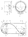
- FIG. 1 The illustration shows a schematically simplified longitudinal section through a refuse collector according to the invention, which is designated overall by 10. It can be seen in the front lower portion of the foot pedal 11, which is attached via a bracket 12 about a horizontal axis 13 pivotally mounted on the housing wall of the waste collector. One recognizes this attachment also in the plan view of Fig. 3. If you now around the visible in Fig. 1 inwardly hinged flap 15 to open the foot pedal 11 is pressed and pressed down, then pivots the bracket 12 about the axis 13 and thus pulls the down on the bow-mounted Bowden cable. From Fig. 1 it can be seen that the lower end of the inner cable of the Bowden cable, which is here designated 16, is connected to the bracket 12.
- the outer jacket 17 is laid within the housing 14 of the waste collector in an approximately spiral path so that the Bowden cable from the front lower portion to the rear upper portion and thereby follows the cylindrical wall of the housing 14 so that the interior of the housing 14 remains free for an inner container to be accommodated there.
- This inner container which is not shown in FIGS. 1 and 3, receives the waste to be dumped.
- the flap 15 pivots inwards about a horizontal axis lying approximately in its upper region (see also FIG. 6), so that, viewed from the outside, for the waste collector 10, a preferably rectangular or depending on the embodiment If necessary, flap also gives round insertion opening.
- a recognizable in Fig. 1 mounting bracket 18 which can be attached to the housing wall.
- the foot pedal 11 extends, as can be seen from Fig. 4, with two webs 19 through slots 20 in the housing wall through and is connected there via a fastening part 21 with the bracket 12.
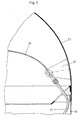
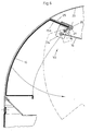
- the Bowden cable whose lower end, as seen in Fig. 1, is connected to the foot pedal 11 and whose course also results from Fig. 1, is shown in its upper rear portion in the detail view of FIG. There are seen the upper end portion of the outer shell 17. There are tabs 22 attached to the upper dome-shaped head portion 23 of the garbage collector, this head part is removable, so you can take out the (not shown) inner bucket. At the tabs 22, the upper end portion of the outer jacket 17 of the Bowden cable is attached. The inner cable 16 then runs, as seen in Fig. 5, further from the rear end of the dome-shaped head portion 23 to the front of the waste bin, where the flap 15 is located. The front upper area with the flap is shown in an enlarged sectional view in Fig. 6, wherein complementing the Fig. 6 and Fig. 5 in principle.
- leg spring 26 is subjected to torsion and tensioned. If the foot pedal 11 is released and thus leaves the traction on the Bowden cable, then the flap 15, 15a is moved back to its original position by the restoring force of the leg spring 26.
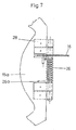
- the leg spring 26 with the leg 26 a which is fixed to the bend 25. Furthermore, one sees the two internal parts of the hinge, which are attached to the dome-shaped head part 23, while the two outer parts 28 of the hinge are attached to the bend 15a of the flap 15.
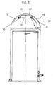
- a variant of a waste collector according to the invention will be explained in more detail with reference to FIGS. 8 and 9.
- the power transmission of at least one Bowden cable in the upper dome-shaped head part of the waste bin on the flap closing the opening 15 structurally slightly different solved to 15 when opening the flap to achieve the largest possible tilt angle and favorable balance of power when opening the door.
- the outer shell 17 is fixed to an abutment 30 in the form of an angle plate and thus ends at a distance from the point 31 of the recorded from the outer sheath 17 Bowden cable on the flap 15.
- This inner cable of the Bowden cable follows the connecting line 33 from the attachment point 32 of the outer shell 17 to the point 31 of the inner cable at the flap.
- abutment 30 is a three-angled angle plate, which is attached to the fixed part of the dome-shaped head portion 23 with a kind of flange 30a.
- a hook 34 is attached to which one end 35 of the inner cable is fixed.
- a fastener for the outer shell 17 is a guide nipple 36 which is attached to the bend 30 b of the angle plate 30. It can be seen that the guide nipple 36 and thus the attachment point 32 of the outer shell 17 is different from the previously with reference to Figures 1 to 6 described embodiment is arranged higher in the dome-shaped head portion 23 as the point of application 31 of the inner cable to the hook 34 and thus on the flap 15. The inner cable thus extends from the attachment point 32 to the point 31 in one slightly descending connecting line 33.
- the hinge axis of the flap 15, that is, the horizontal axis 27 about which it pivots is characterized in that the hook 34 is provided spaced from the point of application 31 of the Bowden cable, so that right at the beginning of the pulling movement is given sufficient torque. Also, the balance of power and the torque after the flap 15 has already covered a certain pivoting continues to be low. From the starting position shown in Fig. 9, the flap 15 passes during its pivotal movement a vertical position and then pivots further inward, with a large pivot angle of, for example, 90 ° or more can be achieved, resulting in a correspondingly large opening for the waste.
- the angle plate 30 has basically a trapezoidal shape with the obtuse angled leg 30b on which the nipple 36 is fixed, one opposite this longer horizontal leg 30c, which extends to the flap 15, one of this then turn obtuse downward angled leg 30d and one of the lower end outgoing approximately at right angles angled leg 30a, which is parallel to an angled portion 25 of the dome-shaped head portion 23 and fixed there.
- the insertion flap 15 has, similar to the previously described embodiment, an angled portion 15a in the upper region, which extends approximately parallel to the angled portion 25.
- the attached to this angled portion 15a hook 34 extends from this bend 15a from initially approximately at right angles down. In the lower area of the hook 34 has an approximately U-shaped a receiving forming formation, in which then the end 35 of the inner cable is fixed.
Landscapes
- Engineering & Computer Science (AREA)
- Mechanical Engineering (AREA)
- Refuse Receptacles (AREA)
- Toilet Supplies (AREA)
- Lock And Its Accessories (AREA)
- External Artificial Organs (AREA)
- Auxiliary Devices For And Details Of Packaging Control (AREA)
Description
- Die vorliegende Erfindung betrifft einen Abfallsammler mit den Merkmalen des Oberbegriffs von Anspruch 1.
- Der bekannte Abfallsammler, von dem die Erfindung ausgeht (US-A-5 163 574), weist im unteren Bereich ein Gehäuse auf sowie ein das Gehäuse oben verschließendes Kopfteil im oberen Bereich. Das Kopfteil weist eine durch eine Klappe verschlossene Einwurföffnung auf. Die Klappe ist durch Betätigung eines unten am Gehäuse angeordneten Fußpedals einwärts schwenkbar. In der zeichnerischen Darstellung hat das Gehäuse einen rechteckigen Umriß, die Beschreibung schränkt jedoch auf rechteckige Gehäuse nicht ein. In der Beschreibung genannter Stand der Technik erwähnt auch Abfallsammler mit etwa zylindrisch ausgebildeten Gehäusen (US-A-4 081 105).
- Zwischen dem Fußpedal und der Klappe ist ein Bowdenzugs vorgesehen, der den wesentlichen Teil der Distanz in vertikaler Richtung zwischen dem Fußpedal und der Klappe überbrückt. Die Klappe ist in Schließrichtung federvorgespannt und wird durch Kraftübertragung mittels des Bowdenzugs beim Treten auf das Fußpedal entgegen der Federvorspannung einwärts geschwenkt. Ein Ende der Seele des Bowdenzugs greift an einer Lasche an der Innenseite der Klappe an, das andere Ende der Seele des Bowdenzugs ist unmittelbar mit dem Fußpedal verbunden. Die Hülle des Bowdenzugs ist im Gehäuse in gerader Linie fest verlegt. Der Bowdenzug besteht aus einer Hülle aus stabilem Kunststoffmaterial und aus einer als Metallkabel ausgeführten Seele.
- Die Praxis hat gezeigt, daß trotz der Hülle aus stabilem Kunststoffmaterial die Funktionseigenschaften der Öffnungsmechanik dieses Abfallsammlers noch nicht optimal sind, so daß der Erfindung das Problem zugrunde liegt, den bekannten Abfallsammler in seinen Funktionseigenschaften zu verbessern.
- Das zuvor aufgezeigte Problem ist bei einem Abfallsammler mit den Merkmalen des Oberbegriffs von Anspruch 1 durch das Merkmal des kennzeichnenden Teils von Anspruch 1 gelöst.
- Unter Beibehaltung eines Bowdenzugs als Kraftübertragungsmittel zwischen Fußpedal und Klappe des Abfallsammlers wird die Querschnittsform des etwa zylindrisch ausgebildeten Gehäuses zu einer optimierten Verlegung des Bowdenzugs innerhalb des Gehäuses genutzt, nämlich mindestens teilweise auf einer etwa spiralförmigen Bahn dem Umfang des Gehäuses folgend. Dadurch besteht die Möglichkeit, daß ein Inneneimer in das Gehäuse des Abfallsammlers hineingestellt werden kann und der Bowdenzug dann zwischen Inneneimer und äußerem Gehäuse verläuft, also im Prinzip auf einer Kurvenbahn. Auf diese Weise kann der Bowdenzug zur Rückseite des Gehäuses und gleichzeitig nach oben geführt werden in einer Art spiralförmigen Bahn. Wird über das Fußpedal auf das untere Ende des Bowdenzugs eine Zugkraft ausgeübt, resultiert daraus eine Zugbewegung des oberen Endes, so daß man den Bowdenzug an der zu schwenkenden Klappe der Einwurföffnung angreifen lassen und diese Klappe einwärts ziehen kann.
- Der Bowdenzug ist als Kraftübertragungsglied zuverlässig, belastbar und läßt eine Vielzahl von Bewegungen zu. Der Bowdenzug ist so flexibel, daß er im Prinzip in einem beliebigen Weg innerhalb des Gehäuses des Abfallsammlers verlegt werden kann, um von dem an der Vorderseite im unteren Bereich angebrachten Fußpedal zu einem oberen rückwärtigen Bereich geführt zu werden, so daß man von dort aus die im oberen vorderen Bereich des Gehäuses befindliche schwenkbare Klappe der Einwurföffnung nach innen schwenken kann. Eine ausreichend große Einwurföffnung wird so gewährleistet. Die Klappe der Einwurföffnung kann beispielsweise einen rechteckigen Umriß haben.
- Die gesamte Öffnungsmechanik für die schwenkbare Klappe kann platzsparend untergebracht werden, so daß der Bowdenzug zwischen dem Außengehäuse und dem Inneneimer verlegt werden kann und auch die übrigen Teile für die Lagerung und Führung des Bowdenzugs keinen Raum in Bereichen beanspruchen, die die Funktion des Abfallsammlers stören. Der Raum oberhalb und hinter der Klappe in dem kugelförmigen Kopfteil, welches in der Regel vom übrigen Gehäuse abnehmbar ist, steht zur Verfügung.
- Man kann das obere Ende des Bowdenzugs beispielsweise an einer Art Lasche oder einem ähnlichen Bauelement angreifen lassen, welches mit der Klappe verbunden ist. Die Klappe der Einwurföffnung kann um die Achse eines Scharniers schwenken, wobei im Scharnierbereich vorzugsweise eine Rückholfeder vorgesehen ist, die bei Loslassen des Fußpedals dafür sorgt, daß sich die Klappe in die Ausgangsstellung (Verschlußstellung) zurückbewegt. Dies kann beispielsweise eine Schenkelfeder sein, die bei Zugkraft durch den Bowdenzug auf Torsion beansprucht wird und dadurch die erforderliche Rückstellkraft zur Verfügung stellt.
- Vorzugsweise sind an einer oder mehreren Stellen Befestigungspunkte, die den Bowdenzug am Außengehäuse des Abfallsammlers innenseitig festlegen. Das untere Ende des Bowdenzugs, insbesondere des Außenzugs, ist vorzugsweise im unteren Bereich an der Vorderseite innenseitig oberhalb des Fußpedals am äußeren Gehäuse des Abfallsammlers gelagert. Hierzu kann beispielsweise ein entsprechendes Winkelteil oder ein anderes Lagerelement verwendet werden, welches an dem Gehäuse angebracht wird. Der Innenzug des Bowdenzugs greift an einer geeigneten Stelle am Fußpedal an bzw. an einem mit dem Fußpedal verbundenen Teil. Das Fußpedal ragt vorzugsweise durch das Gehäuse des Abfallsammlers, beispielsweise durch Schlitze im Gehäuse nach innen und setzt sich dort in einem schwenkbar gelagerten Bauteil fort. Vorzugsweise greift das untere Ende des Bowdenzugs an diesem Bauteil an, vorzugsweise in der Nähe des Bereichs, in dem das Fußpedal nach innen in das Gehäuse hineinragt. An diesem Bauteil kann das untere Ende des Bowdenzugs in geeigneter Weise festgelegt werden, so daß der Bowdenzug die Absenkbewegung des Fußpedals und somit die Schwenkbewegung des genannten Bauteils mit vollzieht. Dieser Hub des Bowdenzugs nach unten beim Absenken des Fußpedals bewirkt einen Zug des oberen Endes des Bowdenzugs, welcher die schwenkbar gelagerte Klappe der Einwurföffnung nach innen zieht.
- Bei einer möglichen bevorzugten Variante der Erfindung ist vorgesehen, daß der Außenmantel eines Bowdenzugs an wenigstens einem Widerlager mit Abstand von dem Angriffspunkt des Innenzugs an der zu öffnenden Klappe festgelegt ist. Dabei ist es wichtig, daß man bereits zu Beginn der Öffnungsbewegung bei Betätigung des Bowdenzugs ein ausreichendes Drehmoment erzeugt und daß auch gegen Ende der Schwenkbewegung der Klappe noch ein ausreichendes Drehmoment gegeben ist um eine genügende Zugkraft zu gewährleisten und einen möglichst großen Winkel bei der Schwenkbewegung der Klappe zu erzielen. Dabei hat es sich als konstruktiv vorteilhaft erwiesen, wenn man den Bowdenzug so anordnet, daß die Verbindungslinie zwischen dem Angriffspunkt des Bowdenzugs und dem Befestigungspunkt des Außenmantels an dem Widerlager etwa in Richtung der Öffnungsrichtung der Klappe zu Beginn der Öffnungsbewegung verläuft. Weiterhin ist es besonders bevorzugt, daß der Befestigungspunkt des Außenmantels des Bowdenzugs an seinem Widerlager mindestens etwa in Höhe des Angriffspunkts des Innenzugs an der Klappe liegt, das heißt, daß der Bowdenzug vor Beginn der Öffnungsbewegung von dem Angriffspunkt an der Klappe ausgehend nicht nach unten, sondern mindestens horizontal oder schräg nach oben verläuft. Dazu kann man ein entsprechend geformtes Widerlager in dem kuppelförmigen Kopfteil des Gehäuses des Abfallsammlers unterbringen. Als Widerlager für den Außenmantel des Bowdenzugs dient beispielsweise ein Blechteil, welches zum Beispiel ein Winkelblech sein kann. Man kann so den Verlauf des Bowdenzugs zur Erzielung günstiger Kräfteverhältnisse optimieren, ohne daß der Bowdenzug dabei zu weit in den Raum unterhalb des kuppelförmigen Kopfteils hineinragt, da ein solcher sich radial im Gehäuse erstreckender Bowdenzug das Einwerfen des Abfalls nach Öffnen der Klappe behindern würde. Es ist also vorteilhaft, wenn auch in diesem oberen Teil der Bowdenzug möglichst nahe der Gehäusekontur des Abfallsammlers folgt und auch das Widerlager und alle für die funktionsfähige Anbringung des Bowdenzugs benötigten Elemente den verfügbaren freien Innenraum des Gehäuses nicht reduzieren.
- Die in den Unteransprüchen genannten Merkmale betreffen bevorzugte Weiterbildungen der erfindungsgemäßen Aufgabenlösung. Weitere konstruktive Details sowie weitere Vorteile bevorzugter Ausführungsvarianten ergeben sich aus der nachfolgenden Detailbeschreibung.
- Nachfolgend wird die vorliegenden Erfindung anhand von Ausführungsbeispielen unter Bezugnahme auf die beiliegenden Zeichnungen näher beschrieben. Darin zeigen
- Fig. 1
- eine schematisch vereinfachte Schnittansicht durch einen Abfallsammler gemäß der Erfindung;
- Fig. 2
- eine Vorderansicht des Abfallsammlers im unteren Bereich,
- Fig. 3
- eine horizontale Schnittdarstellung durch den unteren Bereich des Gehäuses entlang der Linie III - III von Fig. 1;
- Fig. 4
- eine vergrößerte Detaildarstellung eines Ausschnitts aus Fig. 3 im Bereich des Fußpedals;
- Fig. 5
- eine vergrößerte Detaildarstellung im oberen rückwärtigen Bereich des Gehäuseinneren;
- Fig. 6
- eine vergrößerte Detailansicht des oberen vorderen Bereichs des Gehäuseinneren;
- Fig. 7
- eine vergrößerte Detailansicht im Scharnierbereich der schwenkbaren Klappe in der Draufsicht;
- Fig. 8
- eine schematisch vereinfachte Schnittansicht durch einen Abfallsammler gemäß einer Variante der Erfindung;
- Fig. 9
- eine vergrößerte Detailansicht eines Ausschnitts im Bereich des kuppelförmigen Kopfteils des Abfallsammlers gemäß der Variante von Fig. 8.
- Zunächst wird auf Fig. 1 Bezug genommen. Die Darstellung zeigt einen schematisch vereinfachten Längsschnitt durch einen erfindungsgemäßen Abfallsammler, der insgesamt mit 10 bezeichnet ist. Man erkennt im vorderen unteren Bereich das Fußpedal 11, welches über einen Bügel 12 um eine horizontale Achse 13 schwenkbar an der Gehäusewand des Abfallsammlers befestigt ist. Man erkennt diese Befestigung auch in der Draufsicht von Fig. 3. Wenn man nun um die in Fig. 1 erkennbare nach innen schwenkbare Klappe 15 zum Öffnen das Fußpedal 11 betätigt und herunterdrückt, dann schwenkt der Bügel 12 um die Achse 13 und zieht damit den an dem Bügel befestigten Bowdenzug herunter. Aus Fig. 1 ist erkennbar, dass das untere Ende des Innenzugs des Bowdenzugs, der hier mit 16 bezeichnet ist, mit dem Bügel 12 verbunden ist. Der Außenmantel 17 ist innerhalb des Gehäuses 14 des Abfallsammlers in einer etwa spiralförmigen Bahn so verlegt, dass der Bowdenzug von dem vorderen unteren Bereich zum rückwärtigen oberen Bereich verläuft und dabei der zylindrischen Wandung des Gehäuse 14 folgt, damit der Innenraum des Gehäuses 14 frei bleibt für ein dort aufzunehmendes Innenbehältnis. Dieses Innenbehältnis, welches in den Fig. 1 und Fig. 3 nicht dargestellt ist, nimmt den einzuwerfenden Abfall auf. Bei Betätigung des Fußpedals 11 schwenkt die Klappe 15 um eine etwa in ihrem oberen Bereich liegende horizontale Achse einwärts (siehe auch Fig. 6), so dass sich für den Abfallsammler 10 in der Ansicht von außen gesehen, eine vorzugsweise rechteckige oder je nach Ausführung der Klappe gegebenenfalls auch runde Einwurföffnung ergibt.
- Als Widerlager für das untere Ende des Außenmantels 17 des Bowdenzugs dient beispielsweise ein in Fig. 1 erkennbarer Befestigungswinkel 18, der an der Gehäusewand befestigt werden kann. Das Fußpedal 11 erstreckt sich wie man aus Fig. 4 erkennen kann, mit zwei Stegen 19 durch Schlitze 20 in der Gehäusewandung hindurch und ist dort über ein Befestigungsteil 21 mit dem Bügel 12 verbunden.
- Der Bowdenzug dessen unteres Ende, wie man aus Fig. 1 erkennt, mit dem Fußpedal 11 verbunden ist und dessen Verlauf sich ebenfalls aus Fig. 1 ergibt, ist in seinem oberen rückwärtigen Bereich in der Detailansicht gemäß Fig. 5 dargestellt. Dort erkennt man den oberen Endbereich des Außenmantels 17. Es sind Laschen 22 an dem oberen kuppelförmigen Kopfteil 23 des Abfallsammlers angebracht, wobei dieses Kopfteil abnehmbar ist, damit man den (nicht dargestellten) Inneneimer herausnehmen kann. An den Laschen 22 ist der obere Endbereich des Außenmantels 17 des Bowdenzugs befestigt. Der Innenzug 16 verläuft dann, wie man in Fig. 5 erkennt, weiter von dem rückwärtigen Ende des kuppelförmigen Kopfteils 23 zur Vorderseite des Abfallsammlers, wo sich die Klappe 15 befindet. Der vordere obere Bereich mit der Klappe ist in vergrößerter Schnittdarstellung in Fig. 6 gezeigt, wobei sich die Fig. 6 und Fig. 5 im Prinzip ergänzen.
- Man sieht in Fig. 6 den Innenzug 16, der endseitig an einer Lasche 24 befestigt ist, wobei diese Lasche wiederum mit der schwenkbaren Klappe 15 verbunden ist. Oberhalb der Lasche 24 befindet sich an dem kuppelförmigen Kopfteil 23 eine Abwinklung 25, an der eine Schenkelfeder 26 mit ihrem einen Schenkel befestigt ist, wobei der andere Schenkel der Schenkelfeder 26 an der Lasche 24 befestigt ist. Wenn nun bei Betätigung des Fußpedals 11 (siehe Fig. 1) eine Zugkraft auf den Bowdenzug ausgeübt wird, dann zieht dieser an der Lasche 24 und bewegt die Klappe 15 einwärts in die gestrichelte Stellung gemäß Fig. 6, in der die Einwurföffnung frei ist. Die Klappe 15 schwenkt dabei um die horizontale Achse 27, die auch die Achse der Schenkelfeder 26 ist. Dabei wird die Schenkelfeder 26 auf Torsion beansprucht und gespannt. Wird das Fußpedal 11 losgelassen und lässt damit die Zugkraft auf den Bowdenzug nach, dann wird durch die Rückstellkraft der Schenkelfeder 26 die Klappe 15, 15a wieder in ihre Ausgangsstellung zurückbewegt. In der vergrößerten Draufsicht gemäß Fig. 7 erkennt man die Schenkelfeder 26 mit dem Schenkel 26a, der an der Abwinklung 25 festgelegt ist. Weiterhin sieht man die beiden Innenteile des Scharniers, welche an dem kuppelförmigen Kopfteil 23 angebracht sind, während die beiden Außenteile 28 des Scharniers an der Abwinklung 15a der Klappe 15 angebracht sind.
- Nachfolgend wird unter Bezugnahme auf die Fig. 8 und 9 eine Variante eines erfindungsgemäßen Abfallsammlers näher erläutert. Bei dieser Variante ist die Kraftübertragung von mindestens einem Bowdenzug im oberen kuppelförmigen Kopfteil des Abfallsammlers auf die die Einwurföffnung verschließende Klappe 15 konstruktiv etwas anders gelöst, um beim Öffnen der Klappe 15 einen möglichst großen Schwenkwinkel zu erzielen sowie günstige Kräfteverhältnisse beim Öffnen der Klappe. Man erkennt, dass der Außenmantel 17 an einem Widerlager 30 in Form eines Winkelblechs festgelegt ist und damit mit Abstand zu dem Angriffspunkt 31 des von dem Außenmantel 17 aufgenommenen Bowdenzugs an der Klappe 15 endet. Dieser Innenzug des Bowdenzugs folgt der Verbindungslinie 33 von dem Befestigungspunkt 32 des Außenmantels 17 bis zum Angriffspunkt 31 des Innenzugs an der Klappe. Diesbezügliche Einzelheiten sind aus der vergrößerten Detaildarstellung gemäß Fig. 9 besser erkennbar. Als Widerlager 30 dient ein dreifach abgewinkeltes Winkelblech, welches an dem feststehenden Teil des kuppelförmigen Kopfteils 23 mit einer Art Flansch 30a befestigt ist. An der Klappe 15 ist ein Haken 34 angebracht, an dem das eine Ende 35 des Innenzugs festgelegt ist. Als Befestigungselement für den Außenmantel 17 dient ein Führungsnippel 36, der an der Abwinklung 30b des Winkelblechs 30 befestigt ist. Man erkennt, dass der Führungsnippel 36 und somit der Befestigungspunkt 32 des Außenmantels 17 anders als bei dem zuvor unter Bezugnahme auf die Figuren 1 bis 6 beschriebenen Ausführungsbeispiel in dem kuppelförmigen Kopfteil 23 höher angeordnet ist als der Angriffspunkt 31 des Innenzugs an dem Haken 34 und somit an der Klappe 15. Der Innenzug erstreckt sich somit von dem Befestigungspunkt 32 zu dem Angriffspunkt 31 in einer leicht absteigenden Verbindungslinie 33.
- Die Gelenkachse der Klappe 15, das heißt die horizontale Achse 27, um die diese schwenkt ist dadurch, dass der Haken 34 vorgesehen ist zu dem Angriffspunkt 31 des Bowdenzugs beabstandet, so dass gleich zu Beginn der Zugbewegung ein ausreichendes Drehmoment gegeben ist. Auch sind die Kräfteverhältnisse und das Drehmoment nachdem die Klappe 15 bereits einen gewissen Schwenkweg zurückgelegt hat weiterhin günstig. Aus der in Fig. 9 dargestellten Ausgangsposition passiert die Klappe 15 bei ihrer Schwenkbewegung eine vertikale Position und schwenkt dann weiter einwärts, wobei ein großer Schwenkwinkel von beispielsweise 90° oder mehr erzielt werden kann, wodurch sich auch eine entsprechend große Einwurföffnung für den Abfall ergibt.
- Das Winkelblech 30 hat dem Grunde nach eine Trapezform mit dem stumpfwinklig abgewinkelten Schenkel 30b, an dem der Nippel 36 festgelegt ist, einem gegenüber diesem längeren horizontalen Schenkel 30c, der sich zur Klappe 15 hin erstreckt, einem von diesem dann wiederum stumpfwinklig nach unten abgewinkelten Schenkel 30d sowie einem von dessen unterem Ende ausgehenden etwa wiederum rechtwinklig abgewinkelten Schenkel 30a, der parallel zu einer Abwinklung 25 des kuppelförmigen Kopfteils 23 verläuft und dort festgelegt ist. Die Einwurfklappe 15 weist ähnlich wie bei dem zuvor beschriebenen Ausführungsbeispiel im oberen Bereich eine Abwinklung 15a auf, die etwa parallel zu der Abwinklung 25 verläuft. Der an dieser Abwinklung 15a angebrachte Haken 34 erstreckt sich von dieser Abwinklung 15a aus zunächst etwa rechtwinklig nach unten. Im unteren Berech hat der Haken 34 eine etwa U-förmige eine Aufnahme bildende Ausformung, in der dann das Ende 35 des Innenzugs festgelegt ist.
Claims (13)
- Abfallsammler (10) mit einem im unteren Bereich vorgesehenen, etwa zylindrischen Gehäuse (14) sowie mit einem das Gehäuse (14) oben verschließenden kuppelförmigen Kopfteil(23) im oberen Bereich, wobei das Kopfteil (23) an der Frontseite des Abfallsammlers (10) eine durch eine Klappe (15) verschließbare Einwurföffnungaufweist, wobei die Klappe (15) durch Betätigung eines unten am Gehäuse (14) an der Frontseite des Abfallsammlers (10) angeordneten Fußpedals (11) einwärts schwenkbar ist,
wobei zwischen dem Fußpedal (11) und der Klappe (15) ein von der Frontseite zur Rückseite des Abfallsammlers (10) geführter Bowdenzug vorgesehen ist, der zumindest einen wesentlichen Teil der Distanz in vertikaler Richtung zwischen dem Fußpedal (11) und der Klappe (15) überbrückt, und
wobei ein Ende des Bowdenzugs an der die Einwurföffnung verschließenden Klappe (15) angreift und das andere Ende des Bowdenzugs mit dem Fußpedal (11) in Verbindung steht,
dadurch gekennzeichnet,
daß der Bowdenzug innerhalb des Gehäuses (14) zumindest teilweise auf einer etwa spiralförmigen Bahn dem Umfang des Gehäuses (14) folgend verlegt ist. - Abfallsammler (10) nach Anspruch 1, dadurch gekennzeichnet,
daß ein Ende des Innenzugs (16) des Bowdenzugs mit einem schwenkbar gelagerten Bügel (12) verbunden ist, der sich im Inneren des Gehäuses (14) befindet und mit dem außen am Gehäuse (14) angeordneten Fußpedal (11) verbunden ist. - Abfallsammler (10) nach einem der voranstehenden Ansprüche, dadurch gekennzeichnet,
daß der Bowdenzug innerhalb des Gehäuses (14) von der Fußpedalseite zur Rückseite sowie von unten nach oben geführt ist. - Abfallsammler (10) nach einem der voranstehenden Ansprüche, dadurch gekennzeichnet,
daß der Bowdenzug im oberen Bereich des Gehäuses (14) innerhalb des Kopfteils (23) von der Rückseite des Gehäuses (14) mindestens teilweise radial auf die Klappe (15) zu verläuft. - Abfallsammler (10) nach einem der Ansprüche 1 bis 4, dadurch gekennzeichnet, daß das obere Ende des Innenzugs (16) des Bowdenzugs an einem an der Innenseite mit der Klappe (15) verbundenen Teil angreift und bei Absenken des Fußpedals (11) auf dieses Teil eine Zugkraft ausübt.
- Abfallsammler (10) nach Anspruch 5, dadurch gekennzeichnet, daß das obere Ende des Innenzugs (16) an einer mit der Klappe (15) verbundenen Lasche (24) oder dergleichen angreift.
- Abfallsammler (10) nach einem der Ansprüche 1 bis 6, dadurch gekennzeichnet, daß die Klappe (15) um die Achse (27) eines Scharniers, welches sich an der Innenseite der Klappe (15) befindet, schwenkbar befestigt ist.
- Abfallsammler (10) nach einem der Ansprüche 1 bis 7, dadurch gekennzeichnet, daß die Klappe (15) bei Nachlassen der Zugkraft des Bowdenzugs durch die Rückstellkraft einer Feder (26) in die Ausgangsposition zurückgeschwenkt wird.
- Abfallsammler (10) nach Anspruch 8, dadurch gekennzeichnet, daß die Feder (26) eine bei Betätigung der Klappe (15) auf Torsion beanspruchte Schenkelfeder ist.
- Abfallsammler (10) nach einem der Ansprüche 1 bis 9, dadurch gekennzeichnet, daß der Außenmantel (17) des Bowdenzugs an wenigstens einem Widerlager (30) mit Abstand von dem Angriffspunkt (31) des Innenzugs (16) des Bondenzugs an der zu öffnenden Klappe (15) festgelegt ist.
- Abfallsammler (10) nach Anspruch 10, dadurch gekennzeichnet, daß die Verbindungslinie (33) zwischen dem Angriffspunkt (31) des Innenzung (16) und dem Befestigungspunkt (32) des Außenmantels (17) an dem Widerlager (30) etwa in Richtung der Öffnungsrichtung der Klappe (15) zu Beginn der Öffnungsbewegung verläuft.
- Abfallsammler (10) nach Anspruch 10 oder 11 dadurch gekennzeichnet, daß der Befestigungspunkt (32) des Außenmantels(17) des Bowdenzugs an dem Widerlager (30) mindestens etwa in Höhe des Angriffspunkts (31) des Innenzugs (16) an der Klappe (15) liegt.
- Abfallsammler (10) nach einem der Ansprüche 10 bis 12, dadurch gekennzeichnet, daß das Widerlager (30) ein Blech, vorzugsweise ein mindestens teilweise abgewinkeltes Blech (Winkelblech), umfaßt.
Applications Claiming Priority (2)
| Application Number | Priority Date | Filing Date | Title |
|---|---|---|---|
| DE10316157A DE10316157A1 (de) | 2003-04-09 | 2003-04-09 | Abfallsammler |
| DE10316157 | 2003-04-09 |
Publications (2)
| Publication Number | Publication Date |
|---|---|
| EP1468941A1 EP1468941A1 (de) | 2004-10-20 |
| EP1468941B1 true EP1468941B1 (de) | 2007-04-11 |
Family
ID=32892323
Family Applications (1)
| Application Number | Title | Priority Date | Filing Date |
|---|---|---|---|
| EP04003709A Expired - Lifetime EP1468941B1 (de) | 2003-04-09 | 2004-02-19 | Abfallsammler |
Country Status (3)
| Country | Link |
|---|---|
| EP (1) | EP1468941B1 (de) |
| AT (1) | ATE359217T1 (de) |
| DE (2) | DE10316157A1 (de) |
Families Citing this family (1)
| Publication number | Priority date | Publication date | Assignee | Title |
|---|---|---|---|---|
| CN110448256A (zh) * | 2019-07-29 | 2019-11-15 | 华帝股份有限公司 | 一种洗碗机 |
Family Cites Families (8)
| Publication number | Priority date | Publication date | Assignee | Title |
|---|---|---|---|---|
| DE7419741U (de) * | 1974-06-08 | 1974-09-26 | Pueschmann G | Abfallkorb für Autobahnparkplätze oder dergl |
| US1427472A (en) * | 1921-05-21 | 1922-08-29 | Charles C Huber | Garbage container |
| US2759625A (en) * | 1954-06-17 | 1956-08-21 | Ritter John | Refuse container |
| DE3508446A1 (de) * | 1985-03-09 | 1986-09-18 | Reinhard Gabriel, KFZ, Maschinen- und Surfgerätebau, 8963 Waltenhofen | Fernbedienung fuer behaelterklappdeckel |
| DE8913105U1 (de) | 1989-11-06 | 1991-03-14 | Westermann Kg, 59759 Arnsberg | Abfalleimer mit Inneneimer und am Außeneimer anscharniertem Deckel |
| US5163574A (en) * | 1991-02-25 | 1992-11-17 | Sosan Folarin O | Pedal trash bin |
| US5671859A (en) * | 1996-02-01 | 1997-09-30 | Sheu; Miin-Tsang | Door control device for a large garbage container |
| US6390321B1 (en) * | 2000-08-10 | 2002-05-21 | Hwan Yih Enterprise Co., Ltd. | Garbage can with a push-open cap connected with a pedal interactive device |
-
2003
- 2003-04-09 DE DE10316157A patent/DE10316157A1/de not_active Ceased
-
2004
- 2004-02-19 AT AT04003709T patent/ATE359217T1/de not_active IP Right Cessation
- 2004-02-19 DE DE502004003444T patent/DE502004003444D1/de not_active Expired - Lifetime
- 2004-02-19 EP EP04003709A patent/EP1468941B1/de not_active Expired - Lifetime
Also Published As
| Publication number | Publication date |
|---|---|
| ATE359217T1 (de) | 2007-05-15 |
| DE502004003444D1 (de) | 2007-05-24 |
| EP1468941A1 (de) | 2004-10-20 |
| DE10316157A1 (de) | 2004-10-28 |
Similar Documents
| Publication | Publication Date | Title |
|---|---|---|
| EP2020328B1 (de) | Tankklappeneinheit | |
| EP2226437B1 (de) | Spülkasten und Verfahren zum zuführen eines Zusatzmittels bei einem solchen Spülkasten | |
| EP2147178B1 (de) | Scharnieranordnung | |
| EP2274561B1 (de) | Haushaltsgerät | |
| DE10111096A1 (de) | Anordnung einer Frontklappe an einem Fahrzeug | |
| DE60125639T2 (de) | Scharnierstruktur für Motorhaube | |
| DE202010003833U1 (de) | Möbelscharnier | |
| EP2545234B1 (de) | Kraftfahrzeugschloss mit kraftübertragung auf den schlosskasten | |
| EP2281095A1 (de) | Scharnierelement und gehäuse für ein haushaltsgerät | |
| DE102008021337A1 (de) | Scharnierelement und Gehäuse für ein Haushaltsgerät | |
| DE102015122587A1 (de) | Kraftfahrzeugschloss mit Drehfallenabstützung | |
| DE102008021343A1 (de) | Haushaltsgerät | |
| DE3129285C2 (de) | "Behälterdeckel, insbesondere für Großraummüllbehälter | |
| DE102008021340A1 (de) | Scharnierelement und Gehäuse für ein Haushaltsgerät | |
| EP1493688B1 (de) | Abfallsammler | |
| DE4026392C2 (de) | Knickstütze für die Aufstelldächer von Fahrzeugen oder dergleichen | |
| WO1995019306A1 (de) | Schliessvorrichtung für müllbehälter | |
| EP2436615B1 (de) | Müllschleuse | |
| EP1468941A1 (de) | Abfallsammler | |
| DE19911589C5 (de) | Fahrzeugsitz, insbesondere Kraftfahrzeugsitz, mit einer Betätigungseinrichtung | |
| DE3631276C1 (en) | Refuse collector with a lid which can be lifted by spring force | |
| DE102015212411A1 (de) | Schloss mit Hilfsmotor für eine Klappe eines Kraftfahrzeugs | |
| DE69417991T2 (de) | Fussbetätigbarer Müllbehälter | |
| DE69809343T2 (de) | Unterputzspülkasten für eine Doppelkontrolle eines Spülsystems | |
| CH459878A (de) | Zur Aufnahme von Abfällen bestimmter Haushalts-Treteimer aus Kunststoff |
Legal Events
| Date | Code | Title | Description |
|---|---|---|---|
| PUAI | Public reference made under article 153(3) epc to a published international application that has entered the european phase |
Free format text: ORIGINAL CODE: 0009012 |
|
| AK | Designated contracting states |
Kind code of ref document: A1 Designated state(s): AT BE BG CH CY CZ DE DK EE ES FI FR GB GR HU IE IT LI LU MC NL PT RO SE SI SK TR |
|
| AX | Request for extension of the european patent |
Extension state: AL LT LV MK |
|
| 17P | Request for examination filed |
Effective date: 20040908 |
|
| 17Q | First examination report despatched |
Effective date: 20050418 |
|
| AKX | Designation fees paid |
Designated state(s): AT BE BG CH CY CZ DE DK EE ES FI FR GB GR HU IE IT LI LU MC NL PT RO SE SI SK TR |
|
| GRAP | Despatch of communication of intention to grant a patent |
Free format text: ORIGINAL CODE: EPIDOSNIGR1 |
|
| GRAS | Grant fee paid |
Free format text: ORIGINAL CODE: EPIDOSNIGR3 |
|
| GRAA | (expected) grant |
Free format text: ORIGINAL CODE: 0009210 |
|
| AK | Designated contracting states |
Kind code of ref document: B1 Designated state(s): AT BE BG CH CY CZ DE DK EE ES FI FR GB GR HU IE IT LI LU MC NL PT RO SE SI SK TR |
|
| PG25 | Lapsed in a contracting state [announced via postgrant information from national office to epo] |
Ref country code: SI Free format text: LAPSE BECAUSE OF FAILURE TO SUBMIT A TRANSLATION OF THE DESCRIPTION OR TO PAY THE FEE WITHIN THE PRESCRIBED TIME-LIMIT Effective date: 20070411 Ref country code: FI Free format text: LAPSE BECAUSE OF FAILURE TO SUBMIT A TRANSLATION OF THE DESCRIPTION OR TO PAY THE FEE WITHIN THE PRESCRIBED TIME-LIMIT Effective date: 20070411 |
|
| REG | Reference to a national code |
Ref country code: GB Ref legal event code: FG4D Free format text: NOT ENGLISH |
|
| REG | Reference to a national code |
Ref country code: CH Ref legal event code: EP |
|
| REG | Reference to a national code |
Ref country code: IE Ref legal event code: FG4D Free format text: LANGUAGE OF EP DOCUMENT: GERMAN |
|
| REF | Corresponds to: |
Ref document number: 502004003444 Country of ref document: DE Date of ref document: 20070524 Kind code of ref document: P |
|
| GBT | Gb: translation of ep patent filed (gb section 77(6)(a)/1977) |
Effective date: 20070608 |
|
| PG25 | Lapsed in a contracting state [announced via postgrant information from national office to epo] |
Ref country code: SE Free format text: LAPSE BECAUSE OF FAILURE TO SUBMIT A TRANSLATION OF THE DESCRIPTION OR TO PAY THE FEE WITHIN THE PRESCRIBED TIME-LIMIT Effective date: 20070711 |
|
| PG25 | Lapsed in a contracting state [announced via postgrant information from national office to epo] |
Ref country code: ES Free format text: LAPSE BECAUSE OF FAILURE TO SUBMIT A TRANSLATION OF THE DESCRIPTION OR TO PAY THE FEE WITHIN THE PRESCRIBED TIME-LIMIT Effective date: 20070722 |
|
| PG25 | Lapsed in a contracting state [announced via postgrant information from national office to epo] |
Ref country code: PT Free format text: LAPSE BECAUSE OF FAILURE TO SUBMIT A TRANSLATION OF THE DESCRIPTION OR TO PAY THE FEE WITHIN THE PRESCRIBED TIME-LIMIT Effective date: 20070911 |
|
| ET | Fr: translation filed | ||
| REG | Reference to a national code |
Ref country code: IE Ref legal event code: FD4D |
|
| PG25 | Lapsed in a contracting state [announced via postgrant information from national office to epo] |
Ref country code: BG Free format text: LAPSE BECAUSE OF FAILURE TO SUBMIT A TRANSLATION OF THE DESCRIPTION OR TO PAY THE FEE WITHIN THE PRESCRIBED TIME-LIMIT Effective date: 20070711 Ref country code: CZ Free format text: LAPSE BECAUSE OF FAILURE TO SUBMIT A TRANSLATION OF THE DESCRIPTION OR TO PAY THE FEE WITHIN THE PRESCRIBED TIME-LIMIT Effective date: 20070411 Ref country code: IE Free format text: LAPSE BECAUSE OF FAILURE TO SUBMIT A TRANSLATION OF THE DESCRIPTION OR TO PAY THE FEE WITHIN THE PRESCRIBED TIME-LIMIT Effective date: 20070411 Ref country code: DK Free format text: LAPSE BECAUSE OF FAILURE TO SUBMIT A TRANSLATION OF THE DESCRIPTION OR TO PAY THE FEE WITHIN THE PRESCRIBED TIME-LIMIT Effective date: 20070411 |
|
| PLBE | No opposition filed within time limit |
Free format text: ORIGINAL CODE: 0009261 |
|
| STAA | Information on the status of an ep patent application or granted ep patent |
Free format text: STATUS: NO OPPOSITION FILED WITHIN TIME LIMIT |
|
| PG25 | Lapsed in a contracting state [announced via postgrant information from national office to epo] |
Ref country code: SK Free format text: LAPSE BECAUSE OF FAILURE TO SUBMIT A TRANSLATION OF THE DESCRIPTION OR TO PAY THE FEE WITHIN THE PRESCRIBED TIME-LIMIT Effective date: 20070411 |
|
| 26N | No opposition filed |
Effective date: 20080114 |
|
| PG25 | Lapsed in a contracting state [announced via postgrant information from national office to epo] |
Ref country code: IT Free format text: LAPSE BECAUSE OF FAILURE TO SUBMIT A TRANSLATION OF THE DESCRIPTION OR TO PAY THE FEE WITHIN THE PRESCRIBED TIME-LIMIT Effective date: 20070411 Ref country code: GR Free format text: LAPSE BECAUSE OF FAILURE TO SUBMIT A TRANSLATION OF THE DESCRIPTION OR TO PAY THE FEE WITHIN THE PRESCRIBED TIME-LIMIT Effective date: 20070712 |
|
| PG25 | Lapsed in a contracting state [announced via postgrant information from national office to epo] |
Ref country code: RO Free format text: LAPSE BECAUSE OF FAILURE TO SUBMIT A TRANSLATION OF THE DESCRIPTION OR TO PAY THE FEE WITHIN THE PRESCRIBED TIME-LIMIT Effective date: 20070411 |
|
| REG | Reference to a national code |
Ref country code: CH Ref legal event code: PL |
|
| PG25 | Lapsed in a contracting state [announced via postgrant information from national office to epo] |
Ref country code: CH Free format text: LAPSE BECAUSE OF NON-PAYMENT OF DUE FEES Effective date: 20080229 Ref country code: MC Free format text: LAPSE BECAUSE OF NON-PAYMENT OF DUE FEES Effective date: 20080228 Ref country code: LI Free format text: LAPSE BECAUSE OF NON-PAYMENT OF DUE FEES Effective date: 20080229 |
|
| PG25 | Lapsed in a contracting state [announced via postgrant information from national office to epo] |
Ref country code: EE Free format text: LAPSE BECAUSE OF FAILURE TO SUBMIT A TRANSLATION OF THE DESCRIPTION OR TO PAY THE FEE WITHIN THE PRESCRIBED TIME-LIMIT Effective date: 20070411 |
|
| PG25 | Lapsed in a contracting state [announced via postgrant information from national office to epo] |
Ref country code: AT Free format text: LAPSE BECAUSE OF NON-PAYMENT OF DUE FEES Effective date: 20080219 |
|
| PG25 | Lapsed in a contracting state [announced via postgrant information from national office to epo] |
Ref country code: CY Free format text: LAPSE BECAUSE OF FAILURE TO SUBMIT A TRANSLATION OF THE DESCRIPTION OR TO PAY THE FEE WITHIN THE PRESCRIBED TIME-LIMIT Effective date: 20070411 |
|
| PG25 | Lapsed in a contracting state [announced via postgrant information from national office to epo] |
Ref country code: LU Free format text: LAPSE BECAUSE OF NON-PAYMENT OF DUE FEES Effective date: 20080219 Ref country code: HU Free format text: LAPSE BECAUSE OF FAILURE TO SUBMIT A TRANSLATION OF THE DESCRIPTION OR TO PAY THE FEE WITHIN THE PRESCRIBED TIME-LIMIT Effective date: 20071012 |
|
| PG25 | Lapsed in a contracting state [announced via postgrant information from national office to epo] |
Ref country code: TR Free format text: LAPSE BECAUSE OF FAILURE TO SUBMIT A TRANSLATION OF THE DESCRIPTION OR TO PAY THE FEE WITHIN THE PRESCRIBED TIME-LIMIT Effective date: 20070411 |
|
| PGFP | Annual fee paid to national office [announced via postgrant information from national office to epo] |
Ref country code: BE Payment date: 20100401 Year of fee payment: 7 |
|
| BERE | Be: lapsed |
Owner name: HAILO-WERK RUDOLF LOH G.M.B.H. & CO. KG Effective date: 20110228 |
|
| PG25 | Lapsed in a contracting state [announced via postgrant information from national office to epo] |
Ref country code: BE Free format text: LAPSE BECAUSE OF NON-PAYMENT OF DUE FEES Effective date: 20110228 |
|
| REG | Reference to a national code |
Ref country code: DE Ref legal event code: R082 Ref document number: 502004003444 Country of ref document: DE Representative=s name: VON ROHR PATENTANWAELTE PARTNERSCHAFT MBB, DE |
|
| PGFP | Annual fee paid to national office [announced via postgrant information from national office to epo] |
Ref country code: GB Payment date: 20130218 Year of fee payment: 10 Ref country code: FR Payment date: 20130301 Year of fee payment: 10 |
|
| PGFP | Annual fee paid to national office [announced via postgrant information from national office to epo] |
Ref country code: NL Payment date: 20130219 Year of fee payment: 10 |
|
| REG | Reference to a national code |
Ref country code: NL Ref legal event code: V1 Effective date: 20140901 |
|
| GBPC | Gb: european patent ceased through non-payment of renewal fee |
Effective date: 20140219 |
|
| PG25 | Lapsed in a contracting state [announced via postgrant information from national office to epo] |
Ref country code: NL Free format text: LAPSE BECAUSE OF NON-PAYMENT OF DUE FEES Effective date: 20140901 |
|
| REG | Reference to a national code |
Ref country code: FR Ref legal event code: ST Effective date: 20141031 |
|
| PG25 | Lapsed in a contracting state [announced via postgrant information from national office to epo] |
Ref country code: GB Free format text: LAPSE BECAUSE OF NON-PAYMENT OF DUE FEES Effective date: 20140219 Ref country code: FR Free format text: LAPSE BECAUSE OF NON-PAYMENT OF DUE FEES Effective date: 20140228 |
|
| PGFP | Annual fee paid to national office [announced via postgrant information from national office to epo] |
Ref country code: DE Payment date: 20160218 Year of fee payment: 13 |
|
| REG | Reference to a national code |
Ref country code: DE Ref legal event code: R119 Ref document number: 502004003444 Country of ref document: DE |
|
| PG25 | Lapsed in a contracting state [announced via postgrant information from national office to epo] |
Ref country code: DE Free format text: LAPSE BECAUSE OF NON-PAYMENT OF DUE FEES Effective date: 20170901 |