EP1468828A2 - Dispositif de support et de chauffage d'outils - Google Patents
Dispositif de support et de chauffage d'outils Download PDFInfo
- Publication number
- EP1468828A2 EP1468828A2 EP04005689A EP04005689A EP1468828A2 EP 1468828 A2 EP1468828 A2 EP 1468828A2 EP 04005689 A EP04005689 A EP 04005689A EP 04005689 A EP04005689 A EP 04005689A EP 1468828 A2 EP1468828 A2 EP 1468828A2
- Authority
- EP
- European Patent Office
- Prior art keywords
- plate
- electrical
- heating
- honeycomb frame
- openings
- Prior art date
- Legal status (The legal status is an assumption and is not a legal conclusion. Google has not performed a legal analysis and makes no representation as to the accuracy of the status listed.)
- Granted
Links
Images

Classifications
-
- B—PERFORMING OPERATIONS; TRANSPORTING
- B41—PRINTING; LINING MACHINES; TYPEWRITERS; STAMPS
- B41F—PRINTING MACHINES OR PRESSES
- B41F16/00—Transfer printing apparatus
-
- E—FIXED CONSTRUCTIONS
- E03—WATER SUPPLY; SEWERAGE
- E03F—SEWERS; CESSPOOLS
- E03F5/00—Sewerage structures
- E03F5/14—Devices for separating liquid or solid substances from sewage, e.g. sand or sludge traps, rakes or grates
-
- B—PERFORMING OPERATIONS; TRANSPORTING
- B41—PRINTING; LINING MACHINES; TYPEWRITERS; STAMPS
- B41F—PRINTING MACHINES OR PRESSES
- B41F19/00—Apparatus or machines for carrying out printing operations combined with other operations
- B41F19/02—Apparatus or machines for carrying out printing operations combined with other operations with embossing
- B41F19/06—Printing and embossing between a negative and a positive forme after inking and wiping the negative forme; Printing from an ink band treated with colour or "gold"
- B41F19/064—Presses of the reciprocating type
- B41F19/068—Presses of the reciprocating type motor-driven
-
- B—PERFORMING OPERATIONS; TRANSPORTING
- B44—DECORATIVE ARTS
- B44B—MACHINES, APPARATUS OR TOOLS FOR ARTISTIC WORK, e.g. FOR SCULPTURING, GUILLOCHING, CARVING, BRANDING, INLAYING
- B44B5/00—Machines or apparatus for embossing decorations or marks, e.g. embossing coins
- B44B5/02—Dies; Accessories
- B44B5/028—Heated dies
-
- E—FIXED CONSTRUCTIONS
- E03—WATER SUPPLY; SEWERAGE
- E03F—SEWERS; CESSPOOLS
- E03F5/00—Sewerage structures
- E03F5/10—Collecting-tanks; Equalising-tanks for regulating the run-off; Laying-up basins
- E03F5/101—Dedicated additional structures, interposed or parallel to the sewer system
-
- B—PERFORMING OPERATIONS; TRANSPORTING
- B41—PRINTING; LINING MACHINES; TYPEWRITERS; STAMPS
- B41P—INDEXING SCHEME RELATING TO PRINTING, LINING MACHINES, TYPEWRITERS, AND TO STAMPS
- B41P2219/00—Printing presses using a heated printing foil
-
- B—PERFORMING OPERATIONS; TRANSPORTING
- B41—PRINTING; LINING MACHINES; TYPEWRITERS; STAMPS
- B41P—INDEXING SCHEME RELATING TO PRINTING, LINING MACHINES, TYPEWRITERS, AND TO STAMPS
- B41P2219/00—Printing presses using a heated printing foil
- B41P2219/30—Printing dies
- B41P2219/31—Heating means
-
- B—PERFORMING OPERATIONS; TRANSPORTING
- B41—PRINTING; LINING MACHINES; TYPEWRITERS; STAMPS
- B41P—INDEXING SCHEME RELATING TO PRINTING, LINING MACHINES, TYPEWRITERS, AND TO STAMPS
- B41P2219/00—Printing presses using a heated printing foil
- B41P2219/30—Printing dies
- B41P2219/32—Printing dies with means for attaching printing elements to the holder
-
- B—PERFORMING OPERATIONS; TRANSPORTING
- B41—PRINTING; LINING MACHINES; TYPEWRITERS; STAMPS
- B41P—INDEXING SCHEME RELATING TO PRINTING, LINING MACHINES, TYPEWRITERS, AND TO STAMPS
- B41P2219/00—Printing presses using a heated printing foil
- B41P2219/30—Printing dies
- B41P2219/33—Supports for printing dies
Definitions
- the present invention relates to a device for supporting and heating of tools in the form of metal plates used for embossing hot and / or cutting and transfer by hot pressing of portions of films, preferably metallic, on a paper or cardboard substrate mainly.
- Such operations are, for example, carried out in a machine comprising a platen press, in which a sheet of cardboard is brought there to be printed with given patterns from a strip generally metallized pipe between this sheet and the upper box spring heating.
- the pressure required to transfer the metallized film onto the sheet of cardboard is given by the movable lower bed base of the press platinum.
- This movable bed base is generally equipped with a stamping plate, against which the counterparts of each of the tools in the form of upper box spring plate.
- These tools are generally known from a person skilled in the art under the term of stereotypes. So in a vertical movement periodic, the lower bed base will press the counterparts against the clichés correspondents, sandwiching the cardboard sheet above which is stretched the metallized strip.
- the heating of the pictures is therefore made in contact with the nests chassis of bees which, itself, is in direct contact with the upper box spring heating.
- the latter constitutes a heavy and massive part capable of withstand the high pressures generated by the lower movable base during stamping the metallic strip and sometimes even during an operation simultaneous embossing of the sheet.
- Stamping and embossing strength varies depending on the total surface of the patterns to be stamped and can be typically of the order of 1 to 5 MN for areas of worked leaves of almost one approximately square meter. It is inside this box spring that the device resides to heat the honeycomb chassis and therefore the clichés being fixed there.
- Such a box spring generally comprises a massive block rendered secured to the machine frame. Against the lower surface of this block is found at least one support plate, in the thickness of which a plurality of parallel conduits are machined making it possible to house a twenty electric heaters. This support plate is still divided into ten zones, so that the heaters are located in each of these zones, can be supplied together with independently. To this end, an electrical supply network takes also placed inside the upper box spring and connects each group heating body to an external power source. In order to adjust the temperature of the photos to an optimal value, generally between 50 ° C and 180 ° C, the electrical circuit is provided with a thermostatic regulation connected to a plurality of thermal probes. These the latter are generally housed as close as possible to the honeycomb chassis and are distributed according to the areas defined by the different groups of heater.
- Patent FR2'639'005 describes a hot foil stamping device analogous to that exposed so far.
- the heating device of one of the box springs has six independent heating elements separated from each other others by intervals of the order of a millimeter.
- Each heating element consists of a stack of different plates.
- Under this plate is a copper plate acting as a heat distributor.
- Below this last is another milled plate of grooves in which are placed the heating resistors.
- This set of plates rests finally on a last plate formed by compact plastic strips alternated with honeycomb slats. This last plate constitutes a thermal insulation preventing excess heat dispersion to the rest of the bedspring.
- Such heaters have multiple disadvantages which do not facilitate the improvement of the performance of these machines and also make them not very versatile.
- these disadvantages we will mainly mention the great thermal inertia of the many parts massive of these heaters which decrease the performance of the machine when it comes to quickly adapting to new temperature.
- Such a situation can arise, during the same work stamping, when a batch of cardboard sheets is no longer in the same temperature than the previous batch.
- the reasons for such a difference in temperature between these two batches of sheets which can be directly linked to their place of storage, with uneven ambient temperatures, or be due to an increase in machine speed.
- By working sheets of cardboard at a lower temperature it will be necessary to compensate for the heat loss of the plates coming into contact with these sheets in shortest possible time.
- the thermal inertia of all the parts that include the heating devices known to date may require no less than ten minutes before the thermal probes can capture the temperature variation.
- the reaction time to be able to correct such sudden temperature differences is therefore very long compared to the production speed which can be of the order of 4000 or even 7000 sheets per hour.
- Another disadvantage is the difficulty of the systems heating systems to regulate the temperature.
- the heating zones being relatively coarse surfaces, regulating the temperature of areas bordering the honeycomb chassis is generally difficult to get it satisfactorily. Indeed, these peripheral areas are subjected to a temperature gradient which shows a decrease in the temperature of the shot as we approach the edge of the heating plate. This decrease is caused either naturally by surrounding conditions, where the ambient air is at a much lower temperature to that of the stereotypes, either artificially by a wind tunnel placed upstream of the platen press, used to facilitate detachment of the rest of the strip metallic, once stamped on the cardboard sheet. Therefore, if these zones are located not far from the periphery of the heating plate, their temperature can never be made uniform. There will follow a notable reduction in the quality of the transfer of the metallized strip, or even the appearance of faults in these places.
- heaters as described, are difficult to repair and maintain.
- the main organs subject to breakdown being the electrical resistances and the temperature probes.
- the area heating system which could even cripple the entire machine in the event that one or even several photographs were found, even partially, in this area.
- the object of the present invention is to remedy, at least in part, to the aforementioned drawbacks.
- the object of the present invention allows quick and user-friendly adaptability of cutting and stamping machines thanks to a much simpler device to set up and remove from a ordinary box spring. It thus considerably reduces the times necessary to carry out these transformations and improves the versatility of these production machines. It also increases energy efficiency of heating plates, choosing and targeting precisely the different zones to be heated, to decrease the power necessary heating and thereby reduce consumption costs by electricity.
- the object of the present invention also covers the possibility of no longer having to systematically resort to the arrangement of temperature inside the box spring thanks to a system self-regulation integrated in each heating element. In addition, it presents the advantage of considerably reducing the heating and cooling of the machine, respectively before and after production of a given job.
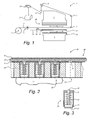
- FIG. 1 shows schematically the main organs a platen press 1 in which the device 20 for supporting and heating of the present invention is arranged therein.
- the platen press 1 is essentially consists of a fixed upper bed base 2 and a box spring lower 3 movable in the vertical direction. Between these box springs at least a metallic film or strip 4, unwound from a reel 5 by a pair of feed rollers 6. Thanks to the arrangement of a plurality of feed rollers reference 7, this metallized strip then goes around the upper bed base 2. It is tensioned by a pair of drive rollers 8 before being removed from the machine by a deflection member 9 and to be evacuated by a pair of brushes 10 towards a recovery tank 11.
- a substrate such as a sheet 12 of cardboard or other material, is deposited on the lower base by a transport member, for example a clamp bar 13 mounted on a chain train 14, as partially shown.
- the lower bed base 3 is equipped with a stamping plate 15 against which at least one counterpart 16 is fixed there.
- the support and heating device 20 of the invention equipped with at least one plate 17 intended to be heated.
- a new sheet 12 is routed and positioned by the clamp bars 13 on the lower bed base 3 equipped with counterparts 16.
- a new portion of metallized strip 4 is unwound from the coil 5 and then stopped next to the pictures 17.
- the rise of the lower bed base 3 being then actuated, it causes the closing of the platen press 1 during which each counterpart 16 comes to fit into the corresponding plate 17. Being sandwiched between these two organs, the sheet 12 and the portion of metallized strip 4 are strongly compressed against each other.
- This compression force to which is added the heat given off by the plate heated, used to cut the imprint of plate 17 in the metallic strip 4 and stick this imprint against the sheet 12 using an adhesive layer specific to each metallized strip.
- a blower 18 allows to breathe air to facilitate separation of sheet 12 from the remaining skeleton metallic strip which sometimes tends to stick to it. Sheet 12 stamped is then removed from the press by the clamp bar 13 and a new cycle can begin.
- FIG. 2 illustrates in more detail the device 20 for supporting and heating which allows to fix the stereotypes 17 of the upper box spring and to raise their temperature up to an optimal working value.
- the device 20 comprises in particular a first non-conductive insulating plate 21 electricity or even thermally insulating, against which is supported by a bottom sheet 22 of copper for example. Against the in front of this sheet is pressed an insulating surface 23 having a almost infinite ohmic resistance.
- the assembly constituted by the insulating plate 21, the bottom plate 22 and the insulating surface 23 can form a whole and constitute thus an organ called base plate 40.
- a honeycomb frame 24 comes then be positioned against this base plate 40, more precisely against the insulating surface 23.
- This chassis is identical in all respects to those used for hot stamping operations in known platen presses of the skilled person.
- a honeycomb chassis has a multitude openings 25, also distributed over its entire surface, and has dimensions substantially equal to the maximum sheet size that it is possible to work with the press in question. Being very expensive to realize, it will be understood that it is also advantageous not to necessarily have to use a specific chassis to be able to implement the object of the present invention.
- the openings 25 are preferably circular in shape and right through the thickness of the honeycomb chassis 24. Through each opening 25 we can see a hole 26 made in the insulating surface 23 so that it is also possible to see part of the bottom sheet 22.
- the openings 25 and the holes 26 are preferably concentric as illustrated in FIG. 2.
- Each opening 25 can receive an independent heating element 30, taking at least support, at one of its ends, against the stripped part of the bottom plate 22 and having, at the other end, a front part intended to come into contact with the back a plate 17 plated and fixed against the outside surface of the nests chassis bee 24.
- FIG. 3 gives a schematic illustration of an element heater 30 of the device 20 of the present invention.
- Each element heater consists in particular of a capsule 31 manufactured in a insulating material which does not allow electrical current to pass.
- This capsule 31 is crossed by an electrode essentially consisting of a bar 32.
- One end of this bar crosses the hole 26 of the insulating surface 23 and comes into contact with the bottom plate 22, and the other end supports a seat 33 sliding along the vertical axis of the bar.
- Elastic means such as a compression spring 34, pushes this seat 33 in direction of the exterior of the opening 25, facing the back of the plate 17.
- the spring of compression 34 is preferably integral, at its ends, respectively from the inner bottom of the capsule 31 and the inner surface of the seat 33.
- any electrical resistance 35 of the heating element 30 is always found properly pressed against the back of plate 17 when the latter is fixed on the honeycomb frame 24. It is intended that the heating element 30 comes snap into opening 25 so that it is easily removable. However, any other means of attachment allowing it to be put on and easily removing it from the opening 25 may also be suitable.
- the bar 32 and the seat 33 constitute one of the electrodes of the support and heating device 20, while the honeycomb frame 24 and plate 17 constitute the other electrode of this device.
- the bottom sheet 22 is therefore connected to the positive polarity of the source electric power and the honeycomb frame 24 is connected to the polarity negative so that the visible parts, such as the chassis and the plate, of the electrical circuit are connected to earth and thus presents no danger when the device is powered on.
- the insulating plate 21, the insulating surface 23 and the capsule insulating 31 which consist in electrically separating the bottom sheet 22 from all the other parts of the device 20 connected to the ground of the platen press 1.
- the electric source not forming part of the present invention, it will not be not described in more detail here.
- the network of electrical wires allowing to connect the bottom plate 22 and the honeycomb chassis 24 to the terminals respective to the electrical source, has no particularities. However, we will still mention that these connections are useful achievable in a very simple way given the access, particularly easy from the outside, offered by both the bottom plate and the honeycomb frame.
- the device 20 of the present invention has no network of internal conductors for the power supply of the electrical organs which it comprises.
- the plates 17 are fixed by means of tight clamps in a few selected openings of the honeycomb frame, near the plate 17. Contributing nothing to the understanding of the present invention, these fastening means have simply not been shown in FIG. 2. However, it will be noted that the device 20 of the present invention therefore allows advantageously to keep this method of fixing the pictures. He never forced therefore by no means the user to invest to equip themselves with a fixing means specific to the device of the present invention.
- the electrical resistors 35 can be present, for example, in the form of ceramic pellets used for heated glue guns in the field of building construction. They can therefore be easily found in specialized shops. These lozenges generally exist in different types, each of which corresponds to a different ohmic resistance.
- the device of the present invention can advantageously be equipped with different electrical resistors 35, depending on the specificity of the work carried out in the platen press. It is therefore also possible to have at the same time, in the device 20, several pads of different ohmic resistances. So it would become possible to heat more part of a plate compared to another or in relation to the rest of the photo for example.
- the device of the present invention makes it possible to place the heating elements 30 at will over the entire surface of the chassis 24, and more judiciously to place them at least inside the covered areas by snapshots 17. Thus, only these snapshots and the chassis surfaces that they occupy will actually be heated by the heating elements 30.
- the pellets, forming the electrical resistors 35 are in direct contact with plate 17. It also results in a gain not negligible from an energy point of view.
- certain types of these resistances electric vehicles could have an inherent self-regulatory power of these pastilles.
- these lozenges could have a composition chemical whose ohmic resistance varies according to the difference between the actual temperature of the tablet and a determined maximum temperature.
- regulating the electric current consumed by each resistor would be done automatically and independently until the tablet reaches the maximum set temperature for which it was designed.
- the heating elements 30 located not far from the blower 18 would automatically absorb more electrical current than those located more in the center of the honeycomb frame, this in order to compensate for the loss of heat generated by the movement of air from the blower. Thanks to that local compensation, which sometimes could even be punctual, a snapshot 17 located near the blower 18 could therefore be heated to a value of almost uniformly.
- this kind of pastilles would no longer require having to systematically use the arrangement of temperature sensors to control the regulation of the different zones heated.
- the support device 20 and heater of the present invention comprises only a few elements and, on the other hand, that the latter are almost all in the form of plates, can be very easily mounted against the bare upper box spring any platen press. Conversely, the disassembly of the device 20 to equip the box spring with tools for cutting cardboard sheets presents no more difficulties.
- FIG. 4 represents a variant of the preferred device of this invention.
- This variant consists in using a base plate 40 formed of a plurality of successive inseparable, insulating and conductive layers 41 42, replacing the insulating plate 21, the bottom plate 22 and the insulating surface 23.
- Such plates are known under the name of circuits multi-layer prints and are commonly used in the field of electronics and IT for making electronic cards, such as graphics cards, motherboards or expansion cards for example. Serving as a support, these multi-layer circuits are therefore a kind of millefeuilles conductive and insulating layers on which are generally soldered electronic components
- the electronic cards To that the electric current can be brought to the surface, from the different conductive layers 42 internal to external surface contacts 44, the electronic cards usually have vias 43, a kind of small rivet insulated metal, which cross all the upper conductive layers, without making electrical contact, until reaching their destination layer at which they are electrically and mechanically connected by a weld 45.
- the heating element 30 comprises an envelope 51 insulator similar to the capsule 31 referred to in Figure 3.
- an insulating jacket 52 containing the main desired members, namely a piston 53 actuated by an elastic actuator 54 such as a compression spring, an electrical resistance 35, a cap 55 conductor and an electronic device 56 which can be a measurement device such as a thermal probe for example.
- the electrical resistance 35 is connected to a medium voltage source via a first electrode 61 intended to be connected to one of the contacts 44 whose potential equivalent to the voltage of 230V for example, and through a second electrode 62 intended to be connected to a second contact 44 whose potential is equivalent to zero voltage for example.
- a third electrode 63 intended to be connected to the last contact 44, allows to put the electronic device 56 under a low voltage, for example 5V, thanks to the potential difference existing between the second and the third electrode.
- the electrodes 61, 62 and 63 are regularly arranged around the insulating jacket 52 and pass through this last through passages 57, to be able to be connected to the element electrical or suitable electronic component.
- the piston 53 is preferably made of insulating material.
- an elastic actuator 54 as a spring
- a piston 53 both conductors.
- the organ electronics 56 is, in the example illustrated in FIG. 5, arranged inside the piston 53.
- the purpose of the cap 55 is here to double the contact surface of electrical resistor 35, thereby improving diffusion heat against plate 17, while keeping this protected pellet at inside the envelope 51.
- This cap 55 can also be produced in a material such as copper or mica as far as this material has good thermal conductivity. However, it could be also considering removing this cap 55 or replacing it simply by the electronic measuring device 56. It is quite clear that the number of electrodes provided in the variant of the heating element 30 could be different in order to obtain either an improvement of this element, or a simplification of its design for example.
Landscapes
- Engineering & Computer Science (AREA)
- Mechanical Engineering (AREA)
- Health & Medical Sciences (AREA)
- Life Sciences & Earth Sciences (AREA)
- Hydrology & Water Resources (AREA)
- Public Health (AREA)
- Water Supply & Treatment (AREA)
- Resistance Heating (AREA)
- Lining Or Joining Of Plastics Or The Like (AREA)
- Printing Methods (AREA)
- Control Of Resistance Heating (AREA)
- Perforating, Stamping-Out Or Severing By Means Other Than Cutting (AREA)
- Casting Or Compression Moulding Of Plastics Or The Like (AREA)
- Moulds For Moulding Plastics Or The Like (AREA)
- Yarns And Mechanical Finishing Of Yarns Or Ropes (AREA)
- Press Drives And Press Lines (AREA)
- Labeling Devices (AREA)
Abstract
Description
- La figure 1 représente, par un schéma de principe, les principaux organes intervenant dans une machine à estamper équipée de l'objet de la présente invention;
- La figure 2 représente schématiquement l'objet de la présente invention dans une vue partielle en coupe verticale;
- La figure 3 représente schématiquement un élément chauffant du dispositif de la présente invention dans une vue en coupe partielle verticale,
- La figure 4 représente schématiquement une variante du dispositif illustré à la figure 2 dans une vue partielle en coupe verticale;
- La figure 5 représente schématiquement une variante d'un élément chauffant tel que représenté dans la figure 4.
Claims (15)
- Dispositif (20) de support et de chauffage d'outils (17), en forme de plaquette métallique, utilisés pour le gaufrage à chaud et/ou le découpage et le transfert par pression à chaud de portions de films (4) sur un substrat (12) dans une machine (1) équipée d'au moins un sommier (2) et d'au moins un châssis nids d'abeilles (24) définissant deux faces parallèles traversées d'une pluralité d'ouvertures (25), caractérisé en ce qu'il comprend une plaque de base (40) appliquée contre l'une des faces du châssis nids d'abeilles (24) et formée d'une alternance d'au moins une surface isolante (21, 23, 41 ) et d'un moins une surface conductrice (22, 42, 44) permettant d'alimenter au moins un élément chauffant (30) pouvant être inséré à l'intérieur de chacune desdites ouvertures (25) en vue d'échauffer un outil (17) fixé contre la seconde face de ce châssis nids d'abeilles (24).
- Dispositif (20) selon la revendication 1, caractérisé en ce que la plaque de base (40) est constituée d'une tôle de fond (22) conductrice contre les faces de laquelle sont appliquées une plaque isolante (21), respectivement une surface isolante (23) perforée d'une pluralité de trous (26) en regard desdites ouvertures (25) du châssis nids d'abeilles (24).
- Dispositif (20) selon la revendication 2, caractérisé en ce que l'élément chauffant (30) comprend une capsule (31 ) isolante traversée d'une électrode (32) dont l'une des extrémités prend appui contre la tôle de fond (22), au travers de l'ouverture (26), et dont l'autre extrémité (33) est dotée d'une résistance électrique (35) destinée à venir au contact d'un outil (17) fixé contre l'une des faces dudit châssis nids d'abeilles (24).
- Dispositif (20) selon la revendication 3, caractérisé en ce que ladite autre extrémité de l'électrode (32) se compose d'une assise (33) poussée vers l'extérieur de l'ouverture (25) par un moyen élastique (34).
- Dispositif (20) selon la revendication 4, caractérisé en ce que ladite assise (33) est montée sur une articulation.
- Dispositif (20) selon la revendication 2, caractérisé en ce que ladite tôle de fond (22) est connectée à la borne positive d'une source d'énergie électrique et en ce que le châssis nids d'abeilles est relié à la borne négative de cette même source.
- Dispositif (20) selon la revendication 1, caractérisé en ce que la plaque de base (40) est constituée d'un circuit imprimé multi-couches (41, 42, 44) comprenant une pluralité de vias (43) disposées au droit des ouvertures (25) du châssis nids d'abeilles (24).
- Dispositif (20) selon la revendication 7, caractérisé en ce que l'élément chauffant (30) comprend une enveloppe 51 à l'intérieur de laquelle sont disposées une pluralité d'électrodes (61, 62, 63) dont l'une de leurs extrémités est reliée à une des polarités d'au moins un organe électrique et/ou au moins un organe électronique (56) et dont leurs autres extrémités sont chacune destinées à venir en contact avec un des vias (43) de la plaque de base (40).
- Dispositif (20) selon la revendication 8, caractérisé en ce qu'au moins un desdits organes électriques est une résistance électrique (35)
- Dispositif (20) selon la revendication 3 et 9, caractérisé en ce que ladite résistance électrique (35) de l'élément chauffant (30) est constituée d'une pastille dont la composition chimique présente une résistance ohmique variant en fonction de l'écart entre la température réelle de la résistance électrique (35) et une température maximale de consigne.
- Dispositif (20) selon la revendication 8, caractérisé en ce que lesdits organes électriques et/ou électroniques et lesdites électrodes (61, 62, 63) sont rendus solidaires d'un piston (53) relié à un actuateur élastique (54) et coulissant le long d'un manteau (52) disposé à l'intérieur de l'enveloppe (51).
- Dispositif (20) selon la revendication 11, caractérisé en ce que l'actuateur élastique (54) constitue une desdites électrodes (61, 62, 63).
- Dispositif (20) selon la revendication 7, caractérisé en ce que le châssis nids d'abeilles (24) est réalisé dans une matière isolante.
- Dispositif (20) selon la revendication 1 caractérisé en ce que lesdits éléments chauffants (30) sont amovibles et sont fixés par encliquetage dans les ouvertures (25) du châssis nids d'abeilles (24).
- Dispositif (20) selon la revendication 1, caractérisé en ce que ladite machine (1) est une presse à platine initialement destinée au découpage et/ou au gaufrage de substrat (12).
Applications Claiming Priority (2)
| Application Number | Priority Date | Filing Date | Title |
|---|---|---|---|
| CH6842003 | 2003-04-16 | ||
| CH6842003 | 2003-04-16 |
Publications (3)
| Publication Number | Publication Date |
|---|---|
| EP1468828A2 true EP1468828A2 (fr) | 2004-10-20 |
| EP1468828A3 EP1468828A3 (fr) | 2009-12-09 |
| EP1468828B1 EP1468828B1 (fr) | 2011-01-12 |
Family
ID=32873503
Family Applications (1)
| Application Number | Title | Priority Date | Filing Date |
|---|---|---|---|
| EP04005689A Expired - Lifetime EP1468828B1 (fr) | 2003-04-16 | 2004-03-10 | Dispositif de support et de chauffage d'outils |
Country Status (11)
| Country | Link |
|---|---|
| US (1) | US6892633B2 (fr) |
| EP (1) | EP1468828B1 (fr) |
| JP (1) | JP2004314175A (fr) |
| KR (1) | KR100542779B1 (fr) |
| CN (1) | CN1332821C (fr) |
| AT (1) | ATE495012T1 (fr) |
| BR (1) | BRPI0401110A (fr) |
| CA (1) | CA2463327A1 (fr) |
| DE (1) | DE602004030969D1 (fr) |
| ES (1) | ES2357835T3 (fr) |
| TW (1) | TWI256342B (fr) |
Cited By (3)
| Publication number | Priority date | Publication date | Assignee | Title |
|---|---|---|---|---|
| WO2012034649A1 (fr) * | 2010-09-16 | 2012-03-22 | Bobst Sa | Dispositif de guidage de bandes pour machine d'estampage |
| WO2012034645A1 (fr) * | 2010-09-16 | 2012-03-22 | Bobst Sa | Dispositif d'impression par estampage |
| US20230001728A1 (en) * | 2021-07-01 | 2023-01-05 | Sekisui Kydex, Llc | Dye sublimation apparatus with a multi-zone independent heater control |
Families Citing this family (25)
| Publication number | Priority date | Publication date | Assignee | Title |
|---|---|---|---|---|
| DE102006008626B4 (de) * | 2006-02-24 | 2008-01-10 | Flooring Technologies Ltd. | Vorrichtung zur Veredelung von Bauplatten |
| DE102009025896A1 (de) * | 2009-06-03 | 2011-01-05 | Technische Universität Graz | Warmumformung mit Einlegematerial |
| TWI474920B (zh) * | 2011-04-05 | 2015-03-01 | Bobst Sa | 熱壓印裝置 |
| CN102229264B (zh) * | 2011-05-06 | 2014-01-15 | 中丰田光电科技(珠海)有限公司 | 定位图案光学纹路烫片布及其制备方法 |
| CN103358677A (zh) * | 2012-03-26 | 2013-10-23 | 李克晓 | 自动烫金(压凸)机蜂窝版版卡 |
| CN102950878B (zh) * | 2012-10-26 | 2015-12-16 | 深圳九星印刷包装集团有限公司 | 一种刀模 |
| US20170080701A1 (en) * | 2015-09-22 | 2017-03-23 | Tian-Sheng Liu | Upper platform with a cooling device, and a working method thereof |
| CN107913890B (zh) * | 2016-10-08 | 2024-08-23 | 宁波荣轩新材料有限公司 | 一种环保型垃圾处理设备 |
| CN107858740B (zh) * | 2017-11-24 | 2024-04-02 | 苏州市康普来新材料有限公司 | 新能源汽车逆变器散热片局部电镀治具 |
| WO2019130143A1 (fr) * | 2017-12-28 | 2019-07-04 | Primatech S.R.L. | Procédé d'accélération de marquage à chaud d'un substrat |
| CN110228288B (zh) * | 2018-03-05 | 2022-09-16 | 博斯特(上海)有限公司 | 吹气装置单元以及烫金模切设备 |
| CN109177474B (zh) * | 2018-09-28 | 2024-02-06 | 上海烟草集团有限责任公司 | 一种烫金设备 |
| US12291012B2 (en) | 2019-03-20 | 2025-05-06 | Bobst Mex Sa | Hot foil stamping press |
| TWI760709B (zh) * | 2019-04-05 | 2022-04-11 | 瑞士商巴柏斯特麥克斯合資公司 | 燙金印刷機 |
| CN111993770B (zh) * | 2020-08-14 | 2021-06-04 | 宜春酷加运动用品有限公司 | 一种具有过热保护的服装生产用压烫装置 |
| US11602945B2 (en) | 2020-10-22 | 2023-03-14 | Yong Jia Chen | Multi-purpose acid-etched metallic stamps and dies |
| CN112848483B (zh) * | 2021-01-08 | 2022-08-30 | 一重集团大连工程技术有限公司 | 用于碳素电极挤压机的电加热型嘴 |
| CN115366532B (zh) * | 2021-05-19 | 2025-05-16 | 昆山和誉祥电子材料有限公司 | 一种可拆卸的压印机加热结构 |
| CN114030280B (zh) * | 2021-10-20 | 2024-03-01 | 绍兴柯桥醉了数码纺织科技股份有限公司 | 一种裁片数码转印设备及其加工工艺 |
| CN116198209B (zh) * | 2021-11-30 | 2025-06-17 | 惠州比亚迪电子有限公司 | 一种基材边框渐变染色装置及方法 |
| CN114468492B (zh) * | 2021-12-22 | 2023-05-30 | 苏州朗坤自动化设备股份有限公司 | 一种智能手环贴胶带设备 |
| CN114228246B (zh) * | 2022-01-04 | 2024-03-26 | 山东鼎润锻压机床有限公司 | 一种pp蜂窝板围板箱在线同步压痕机的加热压制装置 |
| KR102768462B1 (ko) * | 2022-09-27 | 2025-02-13 | 동아대학교 산학협력단 | Stb소재의 전기저항 임피던스 전력제어 가열장치 |
| CN115782362B (zh) * | 2022-11-30 | 2025-08-01 | 上海新倬壮印刷科技有限公司 | 一种无网结太阳能网板用加热装置及其损坏pi膜清除工艺 |
| CN117099811B (zh) * | 2023-09-19 | 2024-09-03 | 临沂惠民早餐工程有限公司 | 一种受热均匀的面食生产加工用发面装置 |
Family Cites Families (21)
| Publication number | Priority date | Publication date | Assignee | Title |
|---|---|---|---|---|
| US3311692A (en) * | 1963-05-08 | 1967-03-28 | Union Carbide Corp | Gravure embossing of thermoplastics |
| US3547751A (en) * | 1967-05-02 | 1970-12-15 | Burton D Morgan | Honeycomb core made from sealed continuous thermoplastic sheets |
| US3584572A (en) * | 1968-02-19 | 1971-06-15 | Anthony Apicella | Method, apparatus and die adapted to simultaneously heat stamp, emboss and cut |
| US3683807A (en) * | 1970-02-24 | 1972-08-15 | Minnesota Mining & Mfg | Duplicating device and method utilizing heat building in an enclosed stack of sheets |
| FR2135471B1 (fr) * | 1971-05-04 | 1973-05-11 | Cellophane Sa | |
| JPS52158613U (fr) * | 1976-05-22 | 1977-12-02 | ||
| US4343670A (en) * | 1979-12-05 | 1982-08-10 | Rheological Systems, Inc. | Apparatus and process for hot-stamping containers |
| US4455933A (en) * | 1982-06-11 | 1984-06-26 | Bichsel Arthur W | Apparatus and method for simultaneously printing and embossing plastic and sealing and/or tear sealing the same |
| JPS60149094U (ja) * | 1984-03-14 | 1985-10-03 | 株式会社村田製作所 | 発熱体装置 |
| US4665303A (en) * | 1984-11-09 | 1987-05-12 | Fuji Photo Film Co., Ltd. | Thermal developing apparatus |
| US4867057A (en) * | 1987-10-21 | 1989-09-19 | American Greetings Corporation | Method and apparatus for simultaneously hot stamping and embossing sheet-like stock material such as paper |
| FR2639005B3 (fr) * | 1988-11-15 | 1991-09-06 | Brunet Jean | Nouveau dispositif de dorure a chaud adaptable aux presses a cylindre |
| EP0507028A1 (fr) * | 1991-04-04 | 1992-10-07 | Malden Mills Industries, Inc. | Traitement d'un tissu genre velours |
| US5562796A (en) * | 1994-05-24 | 1996-10-08 | Dorner Mfg. Corp. | Heat press for joining the spliced ends of a conveyor belt |
| US5517910A (en) * | 1995-01-03 | 1996-05-21 | Preco Industries, Inc. | Self-leveling die platen for die stamping presses |
| US5722320A (en) * | 1996-12-13 | 1998-03-03 | Kemet Corporation | Method and apparatus for aligning die stamping press platens |
| CH691361A5 (fr) * | 1997-06-13 | 2001-07-13 | Bobst Sa | Dispositif pour la fixation d'outils de transfert de films métalliques sur un substrat et procédé pour réaliser un gabarit pour le positionnement de ces outils. |
| JPH11105492A (ja) * | 1997-09-29 | 1999-04-20 | Chan In Kuan | 携帯用ホットスタンプ装置 |
| JP2001158411A (ja) * | 1999-12-02 | 2001-06-12 | Fujitsu Takamisawa Component Ltd | 昇華転写式印刷装置 |
| US6575089B2 (en) * | 2000-03-03 | 2003-06-10 | Eastman Kodak Company | Apparatus and method of heat embossing thin, low density polethylene films |
| US6800833B2 (en) * | 2002-03-29 | 2004-10-05 | Mariusch Gregor | Electromagnetically levitated substrate support |
-
2004
- 2004-03-10 AT AT04005689T patent/ATE495012T1/de not_active IP Right Cessation
- 2004-03-10 DE DE602004030969T patent/DE602004030969D1/de not_active Expired - Lifetime
- 2004-03-10 EP EP04005689A patent/EP1468828B1/fr not_active Expired - Lifetime
- 2004-03-10 ES ES04005689T patent/ES2357835T3/es not_active Expired - Lifetime
- 2004-03-17 TW TW093107063A patent/TWI256342B/zh not_active IP Right Cessation
- 2004-03-30 JP JP2004098376A patent/JP2004314175A/ja active Pending
- 2004-04-05 CN CNB2004100310095A patent/CN1332821C/zh not_active Expired - Fee Related
- 2004-04-06 CA CA002463327A patent/CA2463327A1/fr not_active Abandoned
- 2004-04-13 BR BR0401110-4A patent/BRPI0401110A/pt not_active IP Right Cessation
- 2004-04-15 US US10/826,043 patent/US6892633B2/en not_active Expired - Fee Related
- 2004-04-16 KR KR1020040026068A patent/KR100542779B1/ko not_active Expired - Fee Related
Cited By (12)
| Publication number | Priority date | Publication date | Assignee | Title |
|---|---|---|---|---|
| WO2012034649A1 (fr) * | 2010-09-16 | 2012-03-22 | Bobst Sa | Dispositif de guidage de bandes pour machine d'estampage |
| WO2012034645A1 (fr) * | 2010-09-16 | 2012-03-22 | Bobst Sa | Dispositif d'impression par estampage |
| CN103097137A (zh) * | 2010-09-16 | 2013-05-08 | 鲍勃斯脱梅克斯股份有限公司 | 用于通过烫印来印刷的装置 |
| CN103097136A (zh) * | 2010-09-16 | 2013-05-08 | 鲍勃斯脱梅克斯股份有限公司 | 用于烫印机的箔材导向装置 |
| US8839719B2 (en) | 2010-09-16 | 2014-09-23 | Bobst Mex Sa | Foil guiding device for stamping machine |
| KR101453702B1 (ko) * | 2010-09-16 | 2014-10-22 | 봅스트 맥스 에스에이 | 스탬핑에 의한 인쇄 장치 |
| US8881649B2 (en) | 2010-09-16 | 2014-11-11 | Bobst Mex Sa | Printing device using stamping |
| RU2537283C2 (ru) * | 2010-09-16 | 2014-12-27 | Бобст Мекс Са | Печатающее устройство с использованием тиснения |
| CN103097136B (zh) * | 2010-09-16 | 2015-04-08 | 鲍勃斯脱梅克斯股份有限公司 | 用于烫印机的箔材导向装置 |
| CN103097137B (zh) * | 2010-09-16 | 2015-05-20 | 鲍勃斯脱梅克斯股份有限公司 | 用于通过烫印来印刷的装置 |
| US20230001728A1 (en) * | 2021-07-01 | 2023-01-05 | Sekisui Kydex, Llc | Dye sublimation apparatus with a multi-zone independent heater control |
| US12240260B2 (en) * | 2021-07-01 | 2025-03-04 | Sekisui Kydex, Llc | Dye sublimation apparatus with a multi-zone independent heater control |
Also Published As
| Publication number | Publication date |
|---|---|
| DE602004030969D1 (de) | 2011-02-24 |
| US6892633B2 (en) | 2005-05-17 |
| CN1332821C (zh) | 2007-08-22 |
| EP1468828B1 (fr) | 2011-01-12 |
| CN1541855A (zh) | 2004-11-03 |
| EP1468828A3 (fr) | 2009-12-09 |
| BRPI0401110A (pt) | 2005-01-11 |
| TWI256342B (en) | 2006-06-11 |
| US20040206254A1 (en) | 2004-10-21 |
| KR100542779B1 (ko) | 2006-01-20 |
| TW200508034A (en) | 2005-03-01 |
| ATE495012T1 (de) | 2011-01-15 |
| CA2463327A1 (fr) | 2004-10-16 |
| KR20040090729A (ko) | 2004-10-26 |
| JP2004314175A (ja) | 2004-11-11 |
| ES2357835T3 (es) | 2011-05-03 |
Similar Documents
| Publication | Publication Date | Title |
|---|---|---|
| EP1468828B1 (fr) | Dispositif de support et de chauffage d'outils | |
| US11435682B2 (en) | Heater, fixing device, and image forming apparatus | |
| EP0121467B1 (fr) | Microconnecteur à haute densité de contacts | |
| JP2007518252A5 (fr) | ||
| FR2822295A1 (fr) | Generateur thermoelectrique a semi-conducteurs et ses procedes de fabrication | |
| JP2019525455A5 (fr) | ||
| FR2641436A1 (fr) | ||
| EP0368698B1 (fr) | Dispositif pour l'application d'une cire à épiler | |
| FR2859867A1 (fr) | Element chauffant pour appareil de cuisson | |
| EP0860212A1 (fr) | Applicateur de colle thermofusible et bâtonnet de colle conçu pour alimenter un tel applicateur | |
| EP3056070A1 (fr) | Module électrique, système électrique comportant un tel module électrique, procédés de fabrication correspondants | |
| US2487865A (en) | Photoelectric line scanning | |
| FR2568804A1 (fr) | Machine multi-electrodes pour usinage par decharges electriques | |
| US20220377853A1 (en) | Thin Film Heater | |
| US9007410B2 (en) | Heating head unit and heating head | |
| FR3009133A1 (fr) | Procede de fabrication d'un module thermoelectrique a base de film polymere | |
| CN102487107A (zh) | 导电性膜粘贴装置、结晶系太阳能电池组件装配装置及结晶系太阳能电池单体的连接方法 | |
| KR101892621B1 (ko) | 열전소자 및 그 제조 방법 | |
| EP0067752B1 (fr) | Cellule de couplage thermique et enceinte thermostatée comportant une telle cellule | |
| FR2464579A1 (fr) | Connecteur electrique a forte densite de conducteurs | |
| EP0239434B1 (fr) | Tête d'écriture thermique de type série pour imprimante | |
| FR2477074A1 (fr) | Imprimante agencable pour l'emploi d'un support d'impression choisi parmi une pluralite de supports de types differents | |
| JP4793053B2 (ja) | 面状発熱体 | |
| FR3021839A1 (fr) | Procede de fabrication d'un composant electrique configurable | |
| JP4674564B2 (ja) | 面状発熱体 |
Legal Events
| Date | Code | Title | Description |
|---|---|---|---|
| PUAI | Public reference made under article 153(3) epc to a published international application that has entered the european phase |
Free format text: ORIGINAL CODE: 0009012 |
|
| AK | Designated contracting states |
Kind code of ref document: A2 Designated state(s): AT BE BG CH CY CZ DE DK EE ES FI FR GB GR HU IE IT LI LU MC NL PL PT RO SE SI SK TR |
|
| AX | Request for extension of the european patent |
Extension state: AL LT LV MK |
|
| PUAL | Search report despatched |
Free format text: ORIGINAL CODE: 0009013 |
|
| AK | Designated contracting states |
Kind code of ref document: A3 Designated state(s): AT BE BG CH CY CZ DE DK EE ES FI FR GB GR HU IE IT LI LU MC NL PL PT RO SE SI SK TR |
|
| AX | Request for extension of the european patent |
Extension state: AL LT LV MK |
|
| RIC1 | Information provided on ipc code assigned before grant |
Ipc: B41F 16/00 20060101ALI20091103BHEP Ipc: B41F 19/02 20060101ALI20091103BHEP Ipc: B44C 1/17 20060101ALI20091103BHEP Ipc: B41F 19/06 20060101AFI20040728BHEP |
|
| 17P | Request for examination filed |
Effective date: 20100519 |
|
| GRAP | Despatch of communication of intention to grant a patent |
Free format text: ORIGINAL CODE: EPIDOSNIGR1 |
|
| AKX | Designation fees paid |
Designated state(s): AT BE BG CH CY CZ DE DK EE ES FI FR GB GR HU IE IT LI LU MC NL PL PT RO SE SI SK TR |
|
| GRAS | Grant fee paid |
Free format text: ORIGINAL CODE: EPIDOSNIGR3 |
|
| GRAA | (expected) grant |
Free format text: ORIGINAL CODE: 0009210 |
|
| AK | Designated contracting states |
Kind code of ref document: B1 Designated state(s): AT BE BG CH CY CZ DE DK EE ES FI FR GB GR HU IE IT LI LU MC NL PL PT RO SE SI SK TR |
|
| REG | Reference to a national code |
Ref country code: GB Ref legal event code: FG4D Free format text: NOT ENGLISH |
|
| REG | Reference to a national code |
Ref country code: CH Ref legal event code: EP |
|
| REG | Reference to a national code |
Ref country code: IE Ref legal event code: FG4D Free format text: LANGUAGE OF EP DOCUMENT: FRENCH |
|
| REF | Corresponds to: |
Ref document number: 602004030969 Country of ref document: DE Date of ref document: 20110224 Kind code of ref document: P |
|
| REG | Reference to a national code |
Ref country code: DE Ref legal event code: R096 Ref document number: 602004030969 Country of ref document: DE Effective date: 20110224 |
|
| REG | Reference to a national code |
Ref country code: ES Ref legal event code: FG2A Ref document number: 2357835 Country of ref document: ES Kind code of ref document: T3 Effective date: 20110503 |
|
| REG | Reference to a national code |
Ref country code: NL Ref legal event code: VDEP Effective date: 20110112 |
|
| PG25 | Lapsed in a contracting state [announced via postgrant information from national office to epo] |
Ref country code: SE Free format text: LAPSE BECAUSE OF FAILURE TO SUBMIT A TRANSLATION OF THE DESCRIPTION OR TO PAY THE FEE WITHIN THE PRESCRIBED TIME-LIMIT Effective date: 20110112 Ref country code: GR Free format text: LAPSE BECAUSE OF FAILURE TO SUBMIT A TRANSLATION OF THE DESCRIPTION OR TO PAY THE FEE WITHIN THE PRESCRIBED TIME-LIMIT Effective date: 20110413 Ref country code: PT Free format text: LAPSE BECAUSE OF FAILURE TO SUBMIT A TRANSLATION OF THE DESCRIPTION OR TO PAY THE FEE WITHIN THE PRESCRIBED TIME-LIMIT Effective date: 20110512 |
|
| REG | Reference to a national code |
Ref country code: IE Ref legal event code: FD4D |
|
| PG25 | Lapsed in a contracting state [announced via postgrant information from national office to epo] |
Ref country code: SI Free format text: LAPSE BECAUSE OF FAILURE TO SUBMIT A TRANSLATION OF THE DESCRIPTION OR TO PAY THE FEE WITHIN THE PRESCRIBED TIME-LIMIT Effective date: 20110112 Ref country code: PL Free format text: LAPSE BECAUSE OF FAILURE TO SUBMIT A TRANSLATION OF THE DESCRIPTION OR TO PAY THE FEE WITHIN THE PRESCRIBED TIME-LIMIT Effective date: 20110112 Ref country code: CY Free format text: LAPSE BECAUSE OF FAILURE TO SUBMIT A TRANSLATION OF THE DESCRIPTION OR TO PAY THE FEE WITHIN THE PRESCRIBED TIME-LIMIT Effective date: 20110112 Ref country code: NL Free format text: LAPSE BECAUSE OF FAILURE TO SUBMIT A TRANSLATION OF THE DESCRIPTION OR TO PAY THE FEE WITHIN THE PRESCRIBED TIME-LIMIT Effective date: 20110112 Ref country code: BG Free format text: LAPSE BECAUSE OF FAILURE TO SUBMIT A TRANSLATION OF THE DESCRIPTION OR TO PAY THE FEE WITHIN THE PRESCRIBED TIME-LIMIT Effective date: 20110412 Ref country code: AT Free format text: LAPSE BECAUSE OF FAILURE TO SUBMIT A TRANSLATION OF THE DESCRIPTION OR TO PAY THE FEE WITHIN THE PRESCRIBED TIME-LIMIT Effective date: 20110112 Ref country code: FI Free format text: LAPSE BECAUSE OF FAILURE TO SUBMIT A TRANSLATION OF THE DESCRIPTION OR TO PAY THE FEE WITHIN THE PRESCRIBED TIME-LIMIT Effective date: 20110112 |
|
| BERE | Be: lapsed |
Owner name: BOBST S.A. Effective date: 20110331 |
|
| PG25 | Lapsed in a contracting state [announced via postgrant information from national office to epo] |
Ref country code: DK Free format text: LAPSE BECAUSE OF FAILURE TO SUBMIT A TRANSLATION OF THE DESCRIPTION OR TO PAY THE FEE WITHIN THE PRESCRIBED TIME-LIMIT Effective date: 20110112 Ref country code: MC Free format text: LAPSE BECAUSE OF NON-PAYMENT OF DUE FEES Effective date: 20110331 Ref country code: IE Free format text: LAPSE BECAUSE OF FAILURE TO SUBMIT A TRANSLATION OF THE DESCRIPTION OR TO PAY THE FEE WITHIN THE PRESCRIBED TIME-LIMIT Effective date: 20110112 Ref country code: EE Free format text: LAPSE BECAUSE OF FAILURE TO SUBMIT A TRANSLATION OF THE DESCRIPTION OR TO PAY THE FEE WITHIN THE PRESCRIBED TIME-LIMIT Effective date: 20110112 |
|
| PLBE | No opposition filed within time limit |
Free format text: ORIGINAL CODE: 0009261 |
|
| STAA | Information on the status of an ep patent application or granted ep patent |
Free format text: STATUS: NO OPPOSITION FILED WITHIN TIME LIMIT |
|
| PG25 | Lapsed in a contracting state [announced via postgrant information from national office to epo] |
Ref country code: RO Free format text: LAPSE BECAUSE OF FAILURE TO SUBMIT A TRANSLATION OF THE DESCRIPTION OR TO PAY THE FEE WITHIN THE PRESCRIBED TIME-LIMIT Effective date: 20110112 Ref country code: CZ Free format text: LAPSE BECAUSE OF FAILURE TO SUBMIT A TRANSLATION OF THE DESCRIPTION OR TO PAY THE FEE WITHIN THE PRESCRIBED TIME-LIMIT Effective date: 20110112 Ref country code: SK Free format text: LAPSE BECAUSE OF FAILURE TO SUBMIT A TRANSLATION OF THE DESCRIPTION OR TO PAY THE FEE WITHIN THE PRESCRIBED TIME-LIMIT Effective date: 20110112 |
|
| 26N | No opposition filed |
Effective date: 20111013 |
|
| PG25 | Lapsed in a contracting state [announced via postgrant information from national office to epo] |
Ref country code: BE Free format text: LAPSE BECAUSE OF NON-PAYMENT OF DUE FEES Effective date: 20110331 |
|
| REG | Reference to a national code |
Ref country code: DE Ref legal event code: R097 Ref document number: 602004030969 Country of ref document: DE Effective date: 20111013 |
|
| PGFP | Annual fee paid to national office [announced via postgrant information from national office to epo] |
Ref country code: IT Payment date: 20120323 Year of fee payment: 9 |
|
| PGFP | Annual fee paid to national office [announced via postgrant information from national office to epo] |
Ref country code: ES Payment date: 20130313 Year of fee payment: 10 Ref country code: GB Payment date: 20130306 Year of fee payment: 10 Ref country code: FR Payment date: 20130409 Year of fee payment: 10 Ref country code: CH Payment date: 20130307 Year of fee payment: 10 |
|
| PG25 | Lapsed in a contracting state [announced via postgrant information from national office to epo] |
Ref country code: LU Free format text: LAPSE BECAUSE OF NON-PAYMENT OF DUE FEES Effective date: 20110310 |
|
| PG25 | Lapsed in a contracting state [announced via postgrant information from national office to epo] |
Ref country code: TR Free format text: LAPSE BECAUSE OF FAILURE TO SUBMIT A TRANSLATION OF THE DESCRIPTION OR TO PAY THE FEE WITHIN THE PRESCRIBED TIME-LIMIT Effective date: 20110112 |
|
| PG25 | Lapsed in a contracting state [announced via postgrant information from national office to epo] |
Ref country code: HU Free format text: LAPSE BECAUSE OF FAILURE TO SUBMIT A TRANSLATION OF THE DESCRIPTION OR TO PAY THE FEE WITHIN THE PRESCRIBED TIME-LIMIT Effective date: 20110112 |
|
| REG | Reference to a national code |
Ref country code: CH Ref legal event code: PL |
|
| GBPC | Gb: european patent ceased through non-payment of renewal fee |
Effective date: 20140310 |
|
| REG | Reference to a national code |
Ref country code: FR Ref legal event code: ST Effective date: 20141128 |
|
| PG25 | Lapsed in a contracting state [announced via postgrant information from national office to epo] |
Ref country code: FR Free format text: LAPSE BECAUSE OF NON-PAYMENT OF DUE FEES Effective date: 20140331 Ref country code: GB Free format text: LAPSE BECAUSE OF NON-PAYMENT OF DUE FEES Effective date: 20140310 Ref country code: LI Free format text: LAPSE BECAUSE OF NON-PAYMENT OF DUE FEES Effective date: 20140331 Ref country code: CH Free format text: LAPSE BECAUSE OF NON-PAYMENT OF DUE FEES Effective date: 20140331 |
|
| PG25 | Lapsed in a contracting state [announced via postgrant information from national office to epo] |
Ref country code: IT Free format text: LAPSE BECAUSE OF NON-PAYMENT OF DUE FEES Effective date: 20140310 |
|
| PGFP | Annual fee paid to national office [announced via postgrant information from national office to epo] |
Ref country code: DE Payment date: 20150305 Year of fee payment: 12 |
|
| PG25 | Lapsed in a contracting state [announced via postgrant information from national office to epo] |
Ref country code: ES Free format text: LAPSE BECAUSE OF NON-PAYMENT OF DUE FEES Effective date: 20140311 |
|
| REG | Reference to a national code |
Ref country code: DE Ref legal event code: R119 Ref document number: 602004030969 Country of ref document: DE |
|
| PG25 | Lapsed in a contracting state [announced via postgrant information from national office to epo] |
Ref country code: DE Free format text: LAPSE BECAUSE OF NON-PAYMENT OF DUE FEES Effective date: 20161001 |