EP1468809B1 - Dispositif de serrage maintenant une preforme pour soufflage par etirage bi-axial - Google Patents
Dispositif de serrage maintenant une preforme pour soufflage par etirage bi-axial Download PDFInfo
- Publication number
- EP1468809B1 EP1468809B1 EP02793400.9A EP02793400A EP1468809B1 EP 1468809 B1 EP1468809 B1 EP 1468809B1 EP 02793400 A EP02793400 A EP 02793400A EP 1468809 B1 EP1468809 B1 EP 1468809B1
- Authority
- EP
- European Patent Office
- Prior art keywords
- preform
- cylinder portion
- mouth cylinder
- molding
- leading end
- Prior art date
- Legal status (The legal status is an assumption and is not a legal conclusion. Google has not performed a legal analysis and makes no representation as to the accuracy of the status listed.)
- Expired - Fee Related
Links
Images


Classifications
-
- B—PERFORMING OPERATIONS; TRANSPORTING
- B29—WORKING OF PLASTICS; WORKING OF SUBSTANCES IN A PLASTIC STATE IN GENERAL
- B29C—SHAPING OR JOINING OF PLASTICS; SHAPING OF MATERIAL IN A PLASTIC STATE, NOT OTHERWISE PROVIDED FOR; AFTER-TREATMENT OF THE SHAPED PRODUCTS, e.g. REPAIRING
- B29C49/00—Blow-moulding, i.e. blowing a preform or parison to a desired shape within a mould; Apparatus therefor
- B29C49/42—Component parts, details or accessories; Auxiliary operations
- B29C49/4205—Handling means, e.g. transfer, loading or discharging means
-
- B—PERFORMING OPERATIONS; TRANSPORTING
- B29—WORKING OF PLASTICS; WORKING OF SUBSTANCES IN A PLASTIC STATE IN GENERAL
- B29C—SHAPING OR JOINING OF PLASTICS; SHAPING OF MATERIAL IN A PLASTIC STATE, NOT OTHERWISE PROVIDED FOR; AFTER-TREATMENT OF THE SHAPED PRODUCTS, e.g. REPAIRING
- B29C49/00—Blow-moulding, i.e. blowing a preform or parison to a desired shape within a mould; Apparatus therefor
- B29C49/42—Component parts, details or accessories; Auxiliary operations
- B29C2049/4294—Sealing means
-
- B—PERFORMING OPERATIONS; TRANSPORTING
- B29—WORKING OF PLASTICS; WORKING OF SUBSTANCES IN A PLASTIC STATE IN GENERAL
- B29C—SHAPING OR JOINING OF PLASTICS; SHAPING OF MATERIAL IN A PLASTIC STATE, NOT OTHERWISE PROVIDED FOR; AFTER-TREATMENT OF THE SHAPED PRODUCTS, e.g. REPAIRING
- B29C49/00—Blow-moulding, i.e. blowing a preform or parison to a desired shape within a mould; Apparatus therefor
- B29C49/42—Component parts, details or accessories; Auxiliary operations
- B29C49/58—Blowing means
- B29C2049/5827—Blowing means not touching the preform
-
- B—PERFORMING OPERATIONS; TRANSPORTING
- B29—WORKING OF PLASTICS; WORKING OF SUBSTANCES IN A PLASTIC STATE IN GENERAL
- B29C—SHAPING OR JOINING OF PLASTICS; SHAPING OF MATERIAL IN A PLASTIC STATE, NOT OTHERWISE PROVIDED FOR; AFTER-TREATMENT OF THE SHAPED PRODUCTS, e.g. REPAIRING
- B29C2949/00—Indexing scheme relating to blow-moulding
- B29C2949/07—Preforms or parisons characterised by their configuration
- B29C2949/0715—Preforms or parisons characterised by their configuration the preform having one end closed
-
- B—PERFORMING OPERATIONS; TRANSPORTING
- B29—WORKING OF PLASTICS; WORKING OF SUBSTANCES IN A PLASTIC STATE IN GENERAL
- B29C—SHAPING OR JOINING OF PLASTICS; SHAPING OF MATERIAL IN A PLASTIC STATE, NOT OTHERWISE PROVIDED FOR; AFTER-TREATMENT OF THE SHAPED PRODUCTS, e.g. REPAIRING
- B29C49/00—Blow-moulding, i.e. blowing a preform or parison to a desired shape within a mould; Apparatus therefor
- B29C49/02—Combined blow-moulding and manufacture of the preform or the parison
- B29C49/06—Injection blow-moulding
-
- B—PERFORMING OPERATIONS; TRANSPORTING
- B29—WORKING OF PLASTICS; WORKING OF SUBSTANCES IN A PLASTIC STATE IN GENERAL
- B29C—SHAPING OR JOINING OF PLASTICS; SHAPING OF MATERIAL IN A PLASTIC STATE, NOT OTHERWISE PROVIDED FOR; AFTER-TREATMENT OF THE SHAPED PRODUCTS, e.g. REPAIRING
- B29C49/00—Blow-moulding, i.e. blowing a preform or parison to a desired shape within a mould; Apparatus therefor
- B29C49/42—Component parts, details or accessories; Auxiliary operations
- B29C49/58—Blowing means
-
- B—PERFORMING OPERATIONS; TRANSPORTING
- B29—WORKING OF PLASTICS; WORKING OF SUBSTANCES IN A PLASTIC STATE IN GENERAL
- B29L—INDEXING SCHEME ASSOCIATED WITH SUBCLASS B29C, RELATING TO PARTICULAR ARTICLES
- B29L2031/00—Other particular articles
- B29L2031/712—Containers; Packaging elements or accessories, Packages
- B29L2031/7158—Bottles
Definitions
- the present invention relates to a structure for a preform holding jig to be used in a method of biaxial orientation blow molding of a bottle of a synthetic resin.
- Biaxial orientation blow-molded bottle made of a synthetic resin especially biaxial orientation blow-molded bottle of a polyethylene terephthalate resin are used in many fields and in large numbers as bottle containers, because they exhibit a number of excellent features.
- This biaxial orientation blow-molded bottle of a synthetic resin is generally manufactured by biaxially drawing in the axial direction and in the radial direction and blow-molding a preform, which has been injection-molded into a bottomed cylindrical shape, while heating it to a temperature capable of developing the orientation effect.
- a preform P which is so held by a holding jig 5 as is loosely fitted in an inverted posture by a guide cylinder member 10 and which is heated to a temperature capable of the drawing effect, is assembled with a blow mold 1 together with the holding jig 5 such that a neck ring P1 formed integrally with and circumferentially of the lower end of the outer circumference of a mouth cylinder portion P2 of the preform P is retained on a neck supporting flanged portion 3 of the blow mold 1.
- the preform P is axially drawn and molded in the axial direction by a drawing pin 16, which is inserted into a pin inserting bore 11 formed through in the center of the holding jig 5, and is drawn and molded in the radial direction with the blow air, which is pumped in through the pin inserting bore 11 or the drawing pin 16, so that a bottle P' is molded.
- JP-A-1997-314650 there is described a double blow molding method.
- This method includes: the step of biaxial orientation blow molding the preform into a primary intermediate molding; the step of heating and thermally shrinking the primary intermediate molding into a secondary intermediate molding; and the final step of blow molding the secondary intermediate molding into a bottle.
- the bottle manufactured can have little residual strain and a high heat resistance.
- WO 97/13632 shows a preform holding jig for biaxial orientation blow-molding, in which a support portion or retaining ring holds a preform having a bottomed cylindrical shape formed from a synthetic resin.
- a mouth cylinder portion is inserted into an end portion of a cylindrical jig body, in which a pin inserting bore is formed in the center for inserting a drawing pin therein.
- Said retaining ring is disposed in the inner circumference of the leading end portion of said jig body and gets in external contact with the mouth cylinder portion.
- the present invention has been conceived to solve the aforementioned problems of the prior art, and has a technical object to hold a preform stably in an assembled posture thereby to achieve a safe and high productivity of the biaxial orientation blow-molded bottle.
- Another technical object is to enlarge the passage of air into the preform thereby to achieve a high productivity of the biaxial orientation blow-molded bottle.
- the means of the invention as set forth in Claim 1, 2 and 7 has the followung configuration.
- the preform holding jig for biaxial orientation blow-molding mounting a support portion holding an assembled posture of a preform having a bottomed cylindrical shape formed by a synthetic resin which is assembled by inserting a mouth cylinder portion until an insertion limit, into the leading end portion of a cylindrical jig body in which a pin inserting bore is formed in the center for inserting a drawing pin therein.
- said support portion is disposed in the inner circumference of the leading end portion of said jig body at a position opposed to a peripheral projecting ridge of said mouth cylinder portion, and for making external contact with the outer circumference of said peripheral projecting ridge as to be capable of inserting and extracting said mouth cylinder portion.
- the support portion disposed in the inner circumference of the holding jig makes it possible to insert and extract the mouth cylinder portion so that the insertion and extraction can be performed, if necessary, in the manufacturing process of the bottle.
- the insertion limit of the mouth cylinder portion can be set, for example, by the neck ring formed integrally with and circumferentially of the lower end of the outer circumference of the mouth cylinder portion, by the upper end portion of the mouth cylinder portion and the leading end face of the jig body, or the peripheral abutment against the circumferential step portion suitably added.
- the support portion is constructed to hold the assembled posture of the preform with the holding jig while making contact with the outer circumference of the peripheral projecting ridge of the preform.
- the preform can be held stably in a predetermined assembled posture by the support portion, even when the molding jig is not only attached to but also detached from the blow mold, and the rocking motion of the preform can also be inhibited to prevent the occurrence of production troubles, as might otherwise be caused by losing the posture during the transfer. Therefore, the rocking of the posture of the secondary intermediate being heated in the double blow molding can be eliminated to prevent the defective phenomenon such as the bite of the mold.
- the peripheral projecting ridge is formed in a circumferential ridge shape on the outer circumference of the mouth cylinder portion and at a position below the helical ridge and is named the bead ring or the step portion, too, so that it is utilized as the retaining portion of a pilfer-proof cap.
- the secondary intermediate molding shrunk from the primary intermediate one is mounted in a split mold and is blow molded.
- This secondary intermediate molding is not always fixed due to the thermal shrinkage but is slightly smaller in most cases than the final molding. With a small deflection of the held posture, the defective phenomena such as the contact with the split mold or the bite by the split mold is caused. Therefore, the aforementioned holding jig as set forth in Claim 1 exhibits extremely effective actions and effects in the double blow molding method.
- this support portion holds the posture of the preform from the outside of the preform thereby to inhibit the rocking motion of the preform. This method makes it unnecessary to provide the posture holding portion in the mouth cylinder portion of the preform.
- the inside of the preform can be effectively utilized in its entire inside for the flow passage of the blow air so that the blow air flow can be used to the maximum. This makes it possible to shorten the blowing time period and the cooling time period by the air circulation after the blow thereby to improve the production efficiency.
- the means of the invention and fixes an O-ring in an inner circumference groove formed in the inner circumference of the leading end portion of the jig body thereby to construct the support portion.
- the mouth cylinder portion can be easily inserted and extracted while sliding with the O-ring.
- the O-ring supports makes external contact with the entire outer circumference of the peripheral projecting ridge so that the assembled posture of the preform can be held properly and stably and so that the structure of the support portion is simplified.
- the means of the invention assembles and fixes a holder spring in an inner circumference groove formed in the inner circumference of the leading end portion of the jig body, thereby to construct the support portion.
- the mouth cylinder portion can be easily inserted and extracted by utilizing the function of the holder spring, and the holder spring makes external contact with the outer circumference of the peripheral projecting ridge so that the posture of the preform can be held properly and stably by the elastic force of the holder spring, as set to a desired value.
- the means of the invention as set forth in Claim 3 is constructed by using the holder spring, which makes external contact with the outer circumference of the peripheral projecting ridge of the preform at a plurality of points positioned at substantially equally spaced central angles.
- the mouth cylinder portion is supported at a plurality of points positionedat the substantially equally spaced central angles, without making external contact with the entire outer circumference of the peripheral projecting ridge. Therefore, the attachment and detachment of the preform can be achieved smoothly and reliably with a low resistance to the insertion and extraction.
- the means of the invention as set forth in Claim 4 is constructed by using the holder spring makes external contact with the outer circumference of the peripheral projecting ridge of the preform at three points positioned at substantially equally spaced central angles.
- a two- or four-point support of the mouth cylinder portion is unstable, but the mouth cylinder portion is supported at the three points positioned at the substantially equally spaced central angles so that the deflection of the posture can be reliably suppressed. Because of this small number of supporting points, moreover, the resistance to the insertion and extraction can be so low that the attachment and detachment of the preform can be achieved smoothly and reliably.
- the means of the invention as set forth in Claim 5 is constructed such that the holder spring is made of a wire-shaped metal member and is generally C-shaped to include three straight portions positioned at the substantially equally spaced central angles, and two curved portions connecting the adjoining ones of the straight portions, so that the substantially central portions of the straight portions make external contact with the outer circumference of the peripheral projecting ridge.
- the holder spring has the simple shape which is formed of the generally C-shaped metal wire member, so that the three-point support can be reliably achieved with the two curved portions and the two end portions abutting elastically against the bottom face of the inner circumference groove and with the three straight portions making external contact with the outer circumference of the peripheral projecting ridge at their substantially central portions.
- the holder spring is enabled by its simple shape to have easy attachment and detachment and an excellent durability and can be freed of such a problem that it is brought away from the inner circumference groove by the attachment and detachment of the preform, thereby to achieve a high productivity.
- the simple jig it is possible to realize the attachment to and detachment from the inner circumference groove easily while simplifying the maintenance.
- the means of the invention as set forth in Claim 6 is constructed such that the metal member is formed to have such an elliptical section that its flattened portion makes external contact with the outer circumference of the peripheral projecting ridge.
- the mouth cylinder portion of the preform is inserted with the helical ridge portion formed on the outer circumference being sliding on the generally central portions of the straight portions of the holder spring.
- the sliding face is exemplified by the flattened portion of the metal member having the elliptical section so that the inserting operation of the preform can be smoothly achieved with the wire-shaped metal member being not caught by the groove of the helical ridge.
- the support portion is constructed: by mounting smoothly surfaced ball members in circular transverse holes , in the state opening onto the inner circumference of the cylindrical wall at the leading end portion of said jig body formed to at least three portions at a space of substantially equally central angles with respect to the center axis of said jig body , such that the ball members may be unable to come out and such that they are partially protruded in a pushed state by elastic members; and by providing seal portions in said transverse holes for exhibiting sealing properties against blow air.
- Claim 8 utilizes a function like a ball plunger, and the ball members move under pressure in the transverse holes so that the mouth cylinder portion of the preform can be smoothly inserted into and extracted from the holding jig by actions such as the rotations of the ball members.
- the assembled posture of the preform can be reliably held by the pressure of the elastic members.
- the ball members can be exemplified by those having little deformation due to an external force but an excellent surface slidability, such as stainless steel balls.
- the elastic members can be exemplified by an O-ring shaped member having elastic or rubbery properties or by a coil spring.
- the external contacting positions of the aforementioned O-ring, holder spring or balls with the peripheral projecting ridge can be determined according to the purpose or necessity. It is, however, preferable that the contacting positions are located by abutment against the lower end edge of the peripheral projecting ridge. Then, the lower end edge of the peripheral projecting ridge exhibits the function of the retaining member so that it can support the posture of the preform more reliably.
- the means of the invention as set forth in Claim 8 is constructed such that a neck ring formed integrally with and circumferentially of the lower end of the outer circumference of the mouth cylinder portion is made, with the jig body being attached to the blow mold, to make close abutment against an abutting step portion formed at the leading end open edge portion of the jig body.
- the neck ring makes abutment at its upper face against the abutting step portion to determine the insertion limit of the mouth cylinder portion. Moreover, the neck ring of the preform is clamped, when the preform is mounted in the blow mold, between the blow mold and the abutting step portion of the jig body so that the preform with respect to the blow mold is fixed in a predetermined assembled posture.
- the neck ring of the preform is clamped between the neck supporting flanged portion of the blow mold and the abutting step portion of the jig body.
- the neck ring makes close abutment against the abutting step portion so that the sealing against the blow air is achieved.
- the neck ring is positioned at the lower end of the outer circumference of the mouth cylinder portion of the preform so that the mouth cylinder portion is positioned in its entirety in the blow pressure atmosphere no matter whether its portion might be outside or inside.
- the blow pressure can act homogeneously on the entire surface of the mouth cylinder portion to prevent the occurrence of the defective deformation such as the radially enlarged deformation of the mouth cylinder portion.
- the means of the invention as set forth in Claim 9 is constructed such that with the mouth cylinder portion of the preform being inserted to the insertion limit into the leading end portion of the jig body thereby to hold the posture of the preform, all the construction portions are spaced by at least one half of the internal diameter of the mouth cylinder portion from the center axis of the preform.
- the construction in which with the posture of the preform being held, all the construction portions are spaced by at least one half of the internal diameter of the mouth cylinder portion from the center axis of the preform, is specified such that the column-shaped space having the internal diameter of the mouth cylinder portion but no portion to obstruct the flow of air is retained in the region from the pin inserting bore extending through the center of the jig body to the inside of the mouth cylinder portion of the preform.
- the pin inserting bore of the jig body for the passage to feed the air to the inside of the mouth cylinder portion and the inside of the preform is cleared of the portion which obstructs the flow of air into the preform.
- the passage of air can be widened to the limit so that the flow rate of the blow air can be increased to shorten the blow time period, and the flow rate at the air circulation time can be increased to improve the cooling efficiency thereby to achieve an improvement in the productivity.
- the air blow in the blow molding or the air circulation for cooling the bottle after blown is executed with the drawing pin being inserted in the holding jig and the preform.
- the blow air flows into the preform mainly from the clearance between the outer circumference of the drawing pin and the inner circumference of the mouth cylinder portion.
- the air flows through the passage formed in the drawing pin.
- the effective sectional area to be used for the blow air or circulation air to flow can be determined mainly by the external diameter of the drawing pin.
- the means of the invention as set forth in Claim 10 is constructed such that with a guide cylinder member having a leading end portion radially reduced in a tapered shape and adapted to be inserted into the mouth cylinder portion of the preform is so erected into the pin inserting bore that its leading end portion is protruded from the leading end of the jig body.
- the preform can be easily assembled with the holding jig by using the leading end portion of the guide cylinder member radially reduced in the tapered shape, as the guide. It is, therefore, possible to increase the degree of freedom of the precision design such as the holding jig transfer apparatus and to reduce the production troubles thereby to improve the productivity.
- the posture of the preform can be reliably held by the holding jig support portion of the present invention. Therefore, the guide cylinder member for holding the posture need not always be disposed inside of the preform so that the flow passage of the blow air can be accordingly widened substantially to the limit, as has been described hereinbefore. In the construction of the present invention, however, it is naturally one of branches for selection to employ that guide cylinder member in accordance with the mode of using the holding jig in the manufacture process and the necessity in the manufacture apparatus and the manufacture process.
- the means of the invention as set forth in Claim 11 is constructed such that a retained portion to be retained in an unextractable manner in a transfer apparatus is provided in the outer circumference of the root end portion of the jig body.
- means comprising a cylindrical jig body having a pin inserting bore formed therethrough at its center for a drawing pin to be inserted thereinto, and formed into a cylindrical shape having such an internal diameter that its leading end portion may make loose, external contact with the mouth cylinder portion of such a preform formed of a synthetic resin into a bottomed cylindrical shape, and with the mouth cylinder portion of the preform being inserted to the insertion limit into the leading end portion of the jig body thereby to hold the preform, all the construction portions are spaced by at least one half of the internal diameter of the mouth cylinder portion from the center axis of the preform.
- the construction in which with the posture of the preform being held, all the construction portions are spaced by at least one half of the internal diameter of the mouth cylinder portion from the center axis of the preform, is specified such that the column-shaped space having the internal diameter of the mouth cylinder portion but no portion to obstruct the flow of air is retained in the region from the pin inserting bore extending through the center of the jig body to the inside of the mouth cylinder portion of the preform.
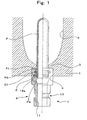
- Fig. 1 shows the state, in which a preform P is attached to a holding jig of a first embodiment according to the present invention and in which the holding jig is mounted in a blow mold 1.
- Fig. 3 shows the state, in which a drawing pin 16 is further inserted.
- Fig. 2 presents a front elevation having half longitudinal section and a top plan view showing a jig body 6.
- the jig body 6 is constructed by merging a fitted cylinder portion 9, which has an external diameter enlarged to be fitted in and assembled with an assembly recess 4 of the blow mold 1, with the upper end of a shank cylinder portion 7 , which has such a retained portion 17 of a circumference groove shape formed in the outer circumference as is to be assembled with the not-shown transfer apparatus and which has a relatively smaller external diameter.
- the shank cylinder portion 7 has an internal diameter slightly larger than that of a mouth cylinder portion P2 of the preform P.
- the fitted cylinder portion 9 has such an internal diameter at its lower portion as is equal to that of the shank cylinder portion 7 and such an internal diameter over a radially enlarged portion that it can make gentle, external contact with a peripheral projecting ridge P3 to receive the mouth cylinder portion P2 easily and that it is radially enlarged upward in a gently counter-tapered shape.
- An inner circumference groove 18a for assembling and holding an O-ring 21 is formed in the inner circumference of the fitted cylinder portion 9 above the height position, which confronts the peripheral projecting ridge P3 of the mouth cylinder portion P2 when the mouth cylinder portion P2 of the preform P is fitted in the fitted cylinder portion 9 from the opening of the upper portion (or the leading end portion) to bring the upper face of a neck ring P1 into abutment against a later-described abutting step portion 13.
- the abutting step portion 13 which makes abutment, while closely contacting, against the upper face of the neck ring P1 thereby to determine the fitting limit of the mouth cylinder portion P2 and to exhibit a sealing effect for the blow air.
- the mouth cylinder portion P2 is positioned in its entirety in the blow pressure atmosphere and is subjected to the uniform blow pressure all over its surface so that it can be prevented from being irregularly deformed or radially enlarged.
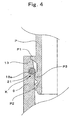
- a support portion K is constructed by assembling and fixing the O-ring 21 with the inner circumference groove 18a.
- This O-ring 21 makes external contact with the lower end edge of the peripheral projecting ridge P3 formed circumferentially of the mouth cylinder portion P2 of the preform P thereby to hold the posture of the preform P (as referred to Fig. 1 and Fig. 4 ).
- the neck ring P1 has its upper face abutting against the abutting step portion 13 of the fitted cylinder portion 9 (as referred to Fig. 4 ), and this abutting portion of the neck ring P1 is in the state to exhibit the active function to hold the posture of the preform P.
- the preform P has its posture supported at the two portions, i.e., the peripheral projecting ridge P3 and the neck ring P1 so that it can be held more reliably in its posture and inhibited in its rocking motion.
- the holding of the assembled position of the preform P with the holding jig should not be limited to the support by that support portion K and the abutting step portion 13 for the neck ring P1.
- the threaded portion of the mouth cylinder portion P2 and the mouth cylinder portion P2 are thermally crystallized (or blushed), for example, the abutment against the leading end face of the mouth cylinder portion P2 can also act to hold the posture.
- the preform P With the j igbody 6 is attached to the blowmold 1, moreover, the preform P is held in its posture by the action of the support portion K, and the neck ring P1 is reliably clamped between the abutting step portion 13 and a neck supporting flanged portion 3 of the blow mold 1. During the blow-drawing molding operation, therefore, the preform P can also be reliably inhibited.
- Fig. 3 shows the state, in which the drawing pin 16 is inserted in a pin inserting bore 11 of the jig body 6.
- the posture of the preform P can be reliably held by the support portion K making external contact with the mouth cylinder portion P2. Unlike the example of the prior art (as referred to Fig. 14 ), therefore, it is unnecessary to provide a guide cylinder member 10 on the inner side of the preform P for holding the posture.
- the shank cylinder portion 7 of the jig body 6 has an internal diameter slightly larger than that of the mouth cylinder portion P2 so that no portion to obstruct the flow of air exists.
- the diameter of the drawing pin 16 can be selected in conformity with a purpose.
- the posture to be taken by the preform P should not be limited to the described one but could be held in any direction according to the purpose or necessity, such as a posture in which the preform P is inserted upward or a posture in which the preform P is inserted horizontally.
- This variable posture has such an effect in the continuous production process, for example, as to widen the degree of freedom for designing or arranging the individual units of the transfer apparatus or the like.
- the support portion K is constructed by mounting a holder spring 22 in the inner circumference groove 18a in place of the O-ring 21 of the first embodiment.
- the holder spring 22 exhibits an inward fastening force with the force of the spring so that it can hold the posture of the preform P more reliably, while making external contact with the peripheral projecting ridge P3 of the preform P, can be inhibited in its rocking motion.
- Fig. 5 (a) shows one example of the holder spring 22, which is rounded in a coiled spring into an O-ring shape.
- This holder spring 22 is fitted in the inner circumference groove 18a with its inner circumference of the O-ring shape being partially protruded from the inner circumference of the fitted cylinder portion 9, and is brought for use into abutment against the lower end portion of the peripheral projecting ridge P3.
- Fig. 5(b) shows another example of the holder spring.
- the holder spring 22 can select the optimum shape, elastic force and so on according to the purpose while balancing the inserting and extracting properties of the mouth cylinder portion P2 and the posture holdability, durability and so on of the preform P.
- Fig. 6 presents a front elevation and a top plan view showing the jig body 6 of a third embodiment of the present invention.
- an outer circumference groove 18b for assembling and holding an outer circumference seal ring 26 having properties of rubber elasticity so that ball members 23 may make abutment against the lower end edge of the peripheral projecting ridge P3 of the mouth cylinder portion P2.
- From the bottom portion of the outer circumference groove 18b moreover, there are formed three circular transverse holes 19, which are so positioned at central angles equally spaced from each other with respect to the center axis of the fitted cylinder portion 9 as to extend through the wall of the fitted cylinder portion 9.
- the ball members 23 are made of stainless steel balls, and the transverse holes 19 are so shaped that their inner end portions are slightly radially reduced.
- the ball members 23 are fitted in those transverse holes 19 and when the outer circumference sealing ring 26 is so set in the outer circumference groove 18b as to hold the ball members 23 from the outside, the ball members 23 are partially protruded to the inner circumference of the fitted cylinder portion 9 (as referred to Fig. 7 ) while being pushed by the outer circumference seal ring 26.
- this outer circumference seal ring 26 constructs a seal portion for exhibiting the sealing properties against the blow pressure, thereby to perform a function to seal the blow air.
- the ball members 23 are partially retained by the lower end edge of the peripheral projecting ridge P3, thereby to make it possible to exhibit the functions to hold the posture of the preform P and to inhibit the rocking motion, more reliably.
- the attachment and detachment of the preform P can be executed without any high resistance by the actions such as the rotations of the ball members 23 (as referred to Fig. 7 ).
- Fig. 8 is an explanatory view of another or a fourth embodiment of the present invention utilizing the actions of the ball members 23.
- a spring 24 performs the function to apply the pressure to the ball member 23, and a plug 27 constructions the seal portion to exhibit the sealing properties against the blow air thereby to perform the function to seal the blow air.
- the actions by the ball members 23 as in the third embodiment and the fourth embodiment can also be achieved by helically assembling a commercially available ball plunger having a helical ridge in its outer circumference, with the transverse hole 19 having a helical ridge, in such a state as can hold the seal.
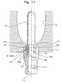
- Fig. 9 to Fig. 12 show a fifth embodiment of the present invention, in which a C-shaped spring 31 (as referred to Fig. 9 ) is used as the holder spring 22 and in which the guide cylinder member 10 is erected in the pin inserting bore 11 (as referred to Fig. 10 ).
- the shank cylinder portion 7 and the fitted cylinder portion 9 are made so separate that the guide cylinder member 10 may be added to the jig body 6, and the sealing properties of the two are retained by a seal portion 37.
- the remaining portions have a structure substantially similar to that of the first embodiment.
- the guide cylinder member 10 is erected from the upper end portion of the shank cylinder portion 7.
- this guide cylinder member 10 is radially reduced in a gently tapered shape toward the leading end portion so that it can be easily inserted into the mouth cylinder portion P2 of the preform P.
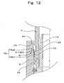
- three straight portions 32 slightly protrude at their generally central portions from an inner circumference 18a2 of the fitted cylinder portion 9 (as referred to Fig. 9 , Fig. 12 and so on). These three points can hold the posture of the preform P to inhibit the rocking motion more reliably while making external contact with the outer circumference, especially the lower end edge of the peripheral projecting ridge P3.
- this three-point supporting method can inhibit the rocking motion more reliably not only than the two-point support but also the four-point support.
- the three-point supporting method is featured in that it can achieve the attachment and detachment of the preform P can be easily achieved.
- this C-shaped spring 31 has a remarkably simple structure and an excellent durability and can be easily replaced by using a simple jig.
- the C-shaped spring 31 does not come out due to the aforementioned vibration or the like of the holding jig being moved but can reduce the trouble in the production so that it can achieve a high productivity.
- the metal member forming the C-shaped spring 31 is formed into an elliptical sectional shape (in which the ratio of the longer diameter to the shorter diameter is set at 2 : 1 (as referred to Fig. 9(b) ).
- the flattened portion 36 of this metal member makes external contact with the lower end edge of the outer circumference of the peripheral projecting ridge P3 (as referred to Fig. 12 ).
- the mouth cylinder portion P2 is inserted with the helical ridge formed on its outer circumference being sliding on the side face of the generally central portion of the straight portion 32 of the C-shaped spring 31.
- the flattened portion 36 of the metal member has the sliding face formed into the elliptical sectional shape so that the metal wire member can achieve the insertion smoothly without being caught by the helical groove.
- the posture of the preform P can be reliably held by the holding jig support portion K of the present invention. It is, therefore, not always necessary unlike the example (as referred to Fig. 14 ) of the prior art to provide the guide cylinder member 10 on the inner side of the preform P for holding the posture of the same. As has been described in connection with the first embodiment, however, the flow passage of the blow air can be accordingly enlarged substantially to the limit. In the construction of the present invention, it is naturally one of options to use the guide cylinder member 10 according to the mode of using the holding jig and the necessities in the manufacture process, the manufacture apparatus and so on.
- the present fifth embodiment is constructed by erecting the guide cylinder member 10.
- the mouth cylinder portion P2 of the preform P can be easily and smoothly assembled with the leading end portion of the jig body 6. It is possible to relax the precision for positioning the holding jig transfer apparatus, for example, and to reduce the production troubles more.
- the double blow molding is executed by using the holding jig of the present fifth embodiment to mold the bottle.
- a secondary intermediate molding is not always fixed in its shape due to the thermal shrinkage and it is made slightly smaller in its size than that of the final molding. But the secondary intermediate molding can be inhibited in its rocking motion and held in a predetermined posture,therefore, at the blow molding step the frequency of occurrence such as the contact with the bottle or the bite by the split mold could be reduced to suppress the percent defective to a remarkably low level.
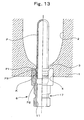
- Fig. 13 shows a sixth embodiment of the present invention, in which the support portion K is omitted from the first embodiment but in which the leading end portion of the jig body 6 is formed into a cylindrical shape having an internal diameter to make loose, external contact with the mouth cylinder portion P2.
- the jig body 6 can hold at least the posture of the preform P, in which the preform P is inverted and inserted in the jig body 6.
- the fitted cylinder portion 9 has such an internal diameter at its upper portion as can make gentle, external contact with the peripheral projecting ridge P3 to insert the mouth cylinder portion P2 easily thereinto and as is radially enlarged upward in a gently counter-tapered shape.
- the internal diameter and the tapered shape can be selected considering the balance of the inserting and extracting properties of the mouth cylinder portion P2 into the jig body 6 and the holdability of the posture.
- the neck ring P1 can be reliably clamped between the abutting step portion 13 and the neck supporting flanged portion 3 of the blow mold 1 thereby to suppress the rocking motion of the preform P being blown.
- the present invention has the construction thus far described so that it can have the following effects.
- the assembled postures of the preform and the blow molding can be reliably held, even when the molding jig is detached from the blow mold, to prevent the occurrence of production troubles, as might otherwise be caused by losing the posture during the transfer, and the deflection of the posture of the secondary intermediate being heated in the double blow molding can be eliminated to prevent the defective phenomenon such as the bite of the mold.
- the flow rate of the blow air can be increased to the excellent moldability and high productivity of a biaxial orientation blow-molded bottle.
- the O-ring supports the preform by making external contact with the entire outer circumference of the peripheral projecting ridge of the mouth cylinder portion so that the posture of the preform can be held properly and stably by the simple structure.
- the posture of the preform can be held properly and stably by the elastic force of the holder spring, as set to a desired value.
- the mouth cylinder portion is supported at a plurality of points positioned at the substantially equally spaced central angles, without making external contact with the entire outer circumference of the peripheral projecting ridge. Therefore, the attachment and detachment of the preform can be achieved smoothly and reliably with a low resistance to the insertion and extraction.
- the mouth cylinder portion is supported at the three points positioned at the substantially equally spaced central angles so that the deflection of the posture can be reliably suppressed. Because of this small number of supporting points, moreover, the resistance to the insertion and extraction can be so low that the attachment and detachment of the preform can be achieved smoothly and reliably.
- the holder spring has the simple shape which is formed of the generally C-shaped metal wire member, so that the three-point support can be reliably achieved.
- the holder spring can have easy attachment and detachment and an excellent durability and can be freed of such a problem that it is brought away from the inner circumference groove by the attachment and detachment of the preform. A high productivity can be achieved while simplifying the maintenance.
- the mouth cylinder portion of the preform is inserted with the helical ridge formed on the outer circumference being sliding on the generally central portions of the straight portions of the holder spring.
- the sliding face is exemplified by the flattened portion of the metal member having the elliptical section so that the inserting operation of the preform can be smoothly achieved with the wire-shaped metal member being not caught by the groove of the helical ridge.
- the ball members can act to hold the posture of the preform stably and to insert and extract the mouth cylinder portion of the preform smoothly and safely.
- the preform can be supported by the neck ring, too, so that the holding of its posture and the suppression of its rocking motion can be more reliably achieved.
- the sealing against the blow air can be achieved by the neck ring so that the blow pressure can act homogeneously on the entire surface of the mouth cylinder portion to prevent the occurrence of the defective deformation such as the radially enlarged deformation of the mouth cylinder portion.
- the holding jig is constructed by clearing the pin inserting bore of the jig body for the passage to feed the air to the inside of the mouth cylinder portion and the inside of the preform, of the portion which obstructs the flow of air into the preform.
- the passage of air can be widened to the limit so that the air flow rate can be increased to shorten the blow time period and to improve the cooling efficiency at the air circulation time thereby to achieve an improvement in the productivity.
- the preform can be easily assembled with the holding jig by using the leading end portion of the guide cylinder member radially reduced in the tapered shape, as the guide. It is, therefore, possible to increase the degree of freedom of the precision design such as the positioning of the holding jig transfer apparatus and to reduce the production troubles thereby to improve the productivity.
- the jig body is reliably fixed on the transfer apparatus by using the retained portion so that it is not raised together to prevent the troubles in the production.
- the holding jig is constructed by clearing the pin inserting bore of the jig body for the passage to feed the air to the inside of the mouth cylinder portion and the inside of the preform, of the portion which obstructs the flow of air into the preform.
- the passage of air can be widened to the limit so that the air flow rate can be increased to shorten the blow time period and to improve the cooling efficiency at the air circulation time thereby to achieve an improvement in the productivity.
- the inner circumference of the leading end portion of the holding jig makes loose, external contact with the mouth cylinder portion of the preform.
- the preform can be supported by the portion of the neck ring, too, so that the holding of its posture and the suppression of its rocking motion can be more reliably achieved.
- the sealing against the blow air can be achieved by the neck ring so that the blow pressure can act homogeneously on the entire surface of the mouth cylinder portion to prevent the occurrence of the defective deformation such as the radially enlarged deformation of the mouth cylinder portion.
- the jig body is reliably fixed on the transfer apparatus by using the retained portion so that it is not raised together to prevent the troubles in the production.
Claims (11)
- Montage de fixation de préforme pour un moulage par soufflage à orientation biaxiale sur lequel est montée une partie de support (K) maintenant une posture assemblée d'une préforme (P) ayant une forme cylindrique avec un fond formée par une résine synthétique qui est assemblée en insérant une partie de cylindre de goulot (P2), jusqu'à une limite d'insertion, dans la partie d'extrémité de tête d'un corps de montage cylindrique (6) au centre duquel un alésage d'insertion de tige (11) est formé pour l'insertion d'une tige d'étirage (16) dans celui-ci,
dans lequel ladite partie de support (K) est disposée dans la circonférence interne de la partie d'extrémité de tête dudit corps de montage (6) à une position opposée à une arête saillante périphérique (P3) de ladite partie de cylindre de goulot (P2), pour établir un contact élastique externe avec la circonférence externe de ladite arête saillante périphérique (P3) de manière à être capable d'insérer et d'extraire ladite partie de cylindre de goulot (P2),
et dans lequel un joint torique (21) est assemblé et fixé dans une gorge circonférentielle interne (18a) formée dans la circonférence interne de la partie d'extrémité de tête dudit corps de montage (6), pour réaliser de ce fait ladite partie de support (K). - Montage de fixation de préforme pour un moulage par soufflage à orientation biaxiale sur lequel est montée une partie de support (K) maintenant une posture assemblée d'une préforme (P) ayant une forme cylindrique avec un fond formée par une résine synthétique qui est assemblée en insérant une partie de cylindre de goulot (P2), jusqu'à une limite d'insertion, dans la partie d'extrémité de tête d'un corps de montage cylindrique (6) au centre duquel un alésage d'insertion de tige (11) est formé pour l'insertion d'une tige d'étirage (16) dans celui-ci,
dans lequel ladite partie de support (K) est disposée dans la circonférence interne de la partie d'extrémité de tête dudit corps de montage (6) à une position opposée à une arête saillante périphérique (P3) de ladite partie de cylindre de goulot (P2), pour établir un contact élastique externe avec la circonférence externe de ladite arête saillante périphérique (P3) de manière à être capable d'insérer et d'extraire ladite partie de cylindre de goulot (P2),
et dans lequel un ressort de maintien (22) est assemblé et fixé dans une gorge circonférentielle interne (18a) formée dans la circonférence interne de la partie d'extrémité de tête dudit corps de montage (6), pour réaliser de ce fait ladite partie de support (K). - Montage de fixation de préforme pour un moulage par soufflage à orientation biaxiale selon la revendication 2, dans lequel le ressort de maintien (22) établit un contact externe avec la circonférence externe de l'arête saillante périphérique (P3) de la préforme (P) en une pluralité de points positionnés à des angles centraux sensiblement régulièrement espacés.
- Montage de fixation de préforme pour un moulage par soufflage à orientation biaxiale selon la revendication 3, dans lequel le ressort de maintien (22) établit un contact externe avec la circonférence externe de l'arête saillante périphérique (P3) de la préforme (P) en trois points positionnés à des angles centraux sensiblement régulièrement espacés.
- Montage de fixation de préforme pour un moulage par soufflage à orientation biaxiale selon la revendication 4, dans lequel le ressort de maintien (22) est constitué d'un élément métallique en forme de fil et est généralement en forme de C de manière à comprendre trois parties droites (32) positionnées aux angles centraux sensiblement régulièrement espacés, et deux parties incurvées (33) reliant les parties contiguës parmi lesdites parties droites (32), de sorte que les parties sensiblement centrales desdites parties droites (32) établissent un contact externe avec la circonférence externe de ladite arête saillante périphérique (P3).
- Montage de fixation de préforme pour un moulage par soufflage à orientation biaxiale selon la revendication 5, dans lequel l'élément métallique est formé de manière à avoir une section elliptique telle que sa partie aplatie (36) établit un contact externe avec la circonférence externe de l'arête saillante périphérique (P3).
- Montage de fixation de préforme pour un moulage par soufflage à orientation biaxiale sur lequel est montée une partie de support (K) maintenant une posture assemblée d'une préforme (P) ayant une forme cylindrique avec un fond formée par une résine synthétique qui est assemblée en insérant une partie de cylindre de goulot (P2), jusqu'à une limite d'insertion, dans la partie d'extrémité de tête d'un corps de montage cylindrique (6) au centre duquel un alésage d'insertion de tige (11) est formé pour l'insertion d'une tige d'étirage (16) dans celui-ci,
dans lequel ladite partie de support (K) est disposée dans la circonférence interne de la partie d'extrémité de tête dudit corps de montage (6) à une position opposée à une arête saillante périphérique (P3) de ladite partie de cylindre de goulot (P2), pour établir un contact élastique externe avec la circonférence externe de ladite arête saillante périphérique (P3) de manière à être capable d'insérer et d'extraire ladite partie de cylindre de goulot (P2),
et dans lequel ladite partie de support (K) est réalisée : en montant des éléments formant billes à surface lisse (23) dans des trous transversaux (19) circulaires formées dans au moins trois parties à des angles centraux sensiblement régulièrement espacés par rapport à l'axe central dudit corps de montage (6), de sorte qu'ils soient incapables de sortir et de sorte qu'ils fassent partiellement saillie dans un état poussés par des éléments élastiques ; et en prévoyant des parties d'étanchéité dans lesdits trous transversaux (19) pour présenter des propriétés d'étanchéité par rapport à l'air de soufflage. - Montage de fixation de préforme pour un moulage par soufflage à orientation biaxiale selon la revendication 1, 2, 3, 4, 5, 6 ou 7, dans lequel une bague de goulot (P1) formée d'un seul tenant avec et circonférentiellement par rapport à l'extrémité inférieure de la circonférence externe de la partie de cylindre de goulot (P2) est réalisée, le corps de montage (6) étant attaché au moule de soufflage (1), pour venir étroitement en butée contre une partie étagée (13) contiguë formée au niveau de la partie de bord ouverte d'extrémité de tête dudit corps de montage (6)
- Montage de fixation de préforme pour un moulage par soufflage à orientation biaxiale selon la revendication 1, 2, 3, 4, 5, 6, 7 ou 8, dans lequel, avec la partie de cylindre de goulot (P2) de la préforme (P) insérée jusqu'à la limite d'insertion dans la partie d'extrémité de tête du corps de montage (6) pour, de ce fait, maintenir la posture de ladite préforme (P), toutes les parties de construction sont espacées d'au moins une moitié du diamètre interne de ladite partie de cylindre de goulot (P2) de l'axe central de ladite préforme (P).
- Montage de fixation de préforme pour un moulage par soufflage à orientation biaxiale selon la revendication 1, 2, 3, 4, 5, 6, 7 ou 8, dans lequel un élément de cylindre de guidage (10) ayant une partie d'extrémité de tête réduite radialement en une forme conique et conçue pour être insérée dans la partie de cylindre de goulot (P2) de la préforme (P) est dressé dans l'alésage d'insertion de tige (11) de sorte que sa partie d'extrémité de tête fait saillie de l'extrémité de tête du corps de montage (6).
- Montage de fixation de préforme pour un moulage par soufflage à orientation biaxiale selon la revendication 1, 2, 3, 4, 5, 6, 7, 8, 9 ou 10, dans lequel une partie retenue (17) devant être retenue d'une manière non extractible dans un appareil de transfert est prévue dans la circonférence externe de la partie d'extrémité de base du corps de montage (6).
Applications Claiming Priority (7)
| Application Number | Priority Date | Filing Date | Title |
|---|---|---|---|
| JP2001400264 | 2001-12-28 | ||
| JP2001400264 | 2001-12-28 | ||
| JP2002024472A JP3979631B2 (ja) | 2002-01-31 | 2002-01-31 | 2軸延伸ブロー成形用プリフォーム保持治具 |
| JP2002024472 | 2002-01-31 | ||
| JP2002349235 | 2002-11-29 | ||
| JP2002349235A JP3950787B2 (ja) | 2001-12-28 | 2002-11-29 | 2軸延伸ブロー成形用プリフォーム保持治具 |
| PCT/JP2002/013582 WO2003057451A1 (fr) | 2001-12-28 | 2002-12-26 | Dispositif de serrage maintenant une preforme pour soufflage par etirage bi-axial |
Publications (3)
| Publication Number | Publication Date |
|---|---|
| EP1468809A1 EP1468809A1 (fr) | 2004-10-20 |
| EP1468809A4 EP1468809A4 (fr) | 2010-06-09 |
| EP1468809B1 true EP1468809B1 (fr) | 2013-07-31 |
Family
ID=27348043
Family Applications (1)
| Application Number | Title | Priority Date | Filing Date |
|---|---|---|---|
| EP02793400.9A Expired - Fee Related EP1468809B1 (fr) | 2001-12-28 | 2002-12-26 | Dispositif de serrage maintenant une preforme pour soufflage par etirage bi-axial |
Country Status (5)
| Country | Link |
|---|---|
| US (1) | US7083407B2 (fr) |
| EP (1) | EP1468809B1 (fr) |
| AU (1) | AU2002360047A1 (fr) |
| CA (1) | CA2453289C (fr) |
| WO (1) | WO2003057451A1 (fr) |
Families Citing this family (16)
| Publication number | Priority date | Publication date | Assignee | Title |
|---|---|---|---|---|
| FR2882963B1 (fr) * | 2005-03-11 | 2009-12-18 | Sidel Sa | Dispositif de transport d'une preforme dans un four, tournette et machine de conditionnement thermique pour installation de soufflage de recipients en materiau thermoplastique comprenant un tel dispositif |
| KR101305230B1 (ko) * | 2005-06-29 | 2013-09-12 | 가부시키가이샤 요시노 고교쇼 | 폴리에스테르 수지제 용기 및 그 성형 방법 |
| FR2903965B1 (fr) * | 2006-07-20 | 2008-12-05 | Sidel Participations | Dispositif de support individuel d'un recipient pourvu d'un col et installation pourvue de dispositifs de transport avec un tel dispositif de support. |
| US7595018B2 (en) * | 2006-10-16 | 2009-09-29 | Husky Injection Molding Systems Ltd. | Molded article picker |
| US20080166209A1 (en) * | 2007-01-10 | 2008-07-10 | Husky Injection Molding Systems Ltd. | Molded Article Picker |
| US7473093B1 (en) * | 2007-09-28 | 2009-01-06 | Husky Injection Molding Systems Ltd. | Molded article picker |
| DE102008036103A1 (de) * | 2008-08-04 | 2010-02-11 | Krones Ag | Vorrichtung zum Expandieren von Behältnissen |
| DE102008049905A1 (de) * | 2008-10-02 | 2010-04-08 | Krones Ag | Schnellwechselsystem für Reckstangen |
| JP5415123B2 (ja) * | 2009-03-31 | 2014-02-12 | 日本碍子株式会社 | 把持治具、並びに、それを用いた計測装置および把持装置 |
| DE102010020092A1 (de) * | 2010-05-10 | 2011-11-10 | Krones Ag | Heizstrecke und Handhabungsvorrichtung für Vorformlinge |
| FR2983427B1 (fr) * | 2011-12-01 | 2013-11-29 | Sidel Participations | Dispositif de soufflage comportant une tuyere et un conduit d'alimentation formant un angle obtus |
| JP5829566B2 (ja) | 2012-03-30 | 2015-12-09 | 株式会社吉野工業所 | ブロー成形装置 |
| DE102013218399A1 (de) * | 2013-09-13 | 2015-03-19 | Krones Ag | Behälterbehandlungsanlage mit einem Ofen und einer Blasformvorrichtung mit Individual-Antrieb von Trägern für Preforms |
| US11597556B2 (en) | 2018-07-30 | 2023-03-07 | Niagara Bottling, Llc | Container preform with tamper evidence finish portion |
| US10987851B2 (en) | 2019-02-26 | 2021-04-27 | Niagara Bottling, Llc | Nozzle for blow-molding stepped finish preform |
| US20200298462A1 (en) * | 2019-03-18 | 2020-09-24 | Niagara Bottling, Llc | Pressure balancing nozzle for blow-molding container preform |
Family Cites Families (9)
| Publication number | Priority date | Publication date | Assignee | Title |
|---|---|---|---|---|
| JPS58154415A (ja) | 1982-03-08 | 1983-09-13 | Fujikura Ltd | 厚肉パイプの製造方法 |
| JPS6062923U (ja) * | 1983-10-06 | 1985-05-02 | 株式会社日本製鋼所 | パリソン又は中空成形品の把持装置 |
| WO1988009717A1 (fr) * | 1987-06-09 | 1988-12-15 | Toyo Seikan Kaisha, Ltd. | Procede de chauffe d'une bouteille ou d'une ebauche en matiere synthetique thermoplastique et procede de regulation de la temperature d'un organe chauffant |
| JPH0622874B2 (ja) * | 1987-06-10 | 1994-03-30 | 東洋製罐株式会社 | 高分子樹脂成型品の加熱方法 |
| JP2914521B2 (ja) * | 1990-06-28 | 1999-07-05 | 株式会社吉野工業所 | 2軸延伸ブロー成形方法 |
| US5340302A (en) * | 1993-07-06 | 1994-08-23 | Husky Injection Molding Systems Ltd. | Apparatus for preparing hollow plastic article |
| JP3336477B2 (ja) | 1994-04-28 | 2002-10-21 | 株式会社吉野工業所 | プリフォーム保持治具 |
| CH690002A5 (fr) * | 1995-10-10 | 2000-03-15 | Tetra Pak Plastics Ltd Tetra P | Machine pour la fabrication de récipient en matière plastique. |
| JP2963904B2 (ja) | 1997-01-23 | 1999-10-18 | 株式会社吉野工業所 | 2軸延伸ブロー成形方法 |
-
2002
- 2002-12-26 EP EP02793400.9A patent/EP1468809B1/fr not_active Expired - Fee Related
- 2002-12-26 WO PCT/JP2002/013582 patent/WO2003057451A1/fr active Application Filing
- 2002-12-26 US US10/480,927 patent/US7083407B2/en not_active Expired - Lifetime
- 2002-12-26 CA CA2453289A patent/CA2453289C/fr not_active Expired - Lifetime
- 2002-12-26 AU AU2002360047A patent/AU2002360047A1/en not_active Abandoned
Also Published As
| Publication number | Publication date |
|---|---|
| US7083407B2 (en) | 2006-08-01 |
| AU2002360047A1 (en) | 2003-07-24 |
| CA2453289A1 (fr) | 2003-07-17 |
| WO2003057451A1 (fr) | 2003-07-17 |
| CA2453289C (fr) | 2011-03-15 |
| EP1468809A4 (fr) | 2010-06-09 |
| US20040121038A1 (en) | 2004-06-24 |
| EP1468809A1 (fr) | 2004-10-20 |
Similar Documents
| Publication | Publication Date | Title |
|---|---|---|
| EP1468809B1 (fr) | Dispositif de serrage maintenant une preforme pour soufflage par etirage bi-axial | |
| US7976767B2 (en) | Lightweight preform and method of manufacture | |
| FI75522C (fi) | Saett och anordning foer formning av en behaollare. | |
| JP4612023B2 (ja) | ネック部付き容器の個別支持装置およびかかる支持装置を使用した移送装置を備えた設備 | |
| US6672470B2 (en) | Process for improving material thickness distribution within a molded bottle and a bottle therefrom | |
| WO1995029804A1 (fr) | Procede de moulage par soufflage a orientation biaxiale et gabarit de maintien de preforme | |
| EP0503086B1 (fr) | Ebauche de moulage d'un récipient en matière plastique et moule pour une ébauche de moulage. | |
| US10654212B2 (en) | Liquid blow molding apparatus and liquid blow molding method | |
| JP3950787B2 (ja) | 2軸延伸ブロー成形用プリフォーム保持治具 | |
| WO2013099120A1 (fr) | Dispositif et procédé de moulage par soufflage | |
| JP4805040B2 (ja) | Petボトルブロー成形用ノズル | |
| US7008215B2 (en) | Multiple finish spindle | |
| WO1999039895A1 (fr) | Bouteille en plastique dont la base presente plusieurs parties pieds distinctes | |
| CN106457651A (zh) | 用于接合预成型件的夹持设备 | |
| CN101254646B (zh) | 吹塑模具 | |
| US9849620B2 (en) | Container preform | |
| US20180029750A1 (en) | Method and Apparatus for Blow-Moulded Stackable Receptacles | |
| JP3979631B2 (ja) | 2軸延伸ブロー成形用プリフォーム保持治具 | |
| JPH07205997A (ja) | 把手付き合成樹脂製容器の成形方法及び装置 | |
| JP4266433B2 (ja) | 把手付き容器成形用プリフォーム | |
| JP7370799B2 (ja) | プリフォーム加熱方法 | |
| CN220618741U (zh) | 一种用于玻璃瓶制造的芯子 | |
| JP6925129B2 (ja) | ブロー成形容器 | |
| CN212603333U (zh) | 吹瓶模具、吹瓶机及塑料瓶 | |
| JP4251026B2 (ja) | 合成樹脂製容器の製造方法 |
Legal Events
| Date | Code | Title | Description |
|---|---|---|---|
| PUAI | Public reference made under article 153(3) epc to a published international application that has entered the european phase |
Free format text: ORIGINAL CODE: 0009012 |
|
| 17P | Request for examination filed |
Effective date: 20040727 |
|
| AK | Designated contracting states |
Kind code of ref document: A1 Designated state(s): AT BE BG CH CY CZ DE DK EE ES FI FR GB GR IE IT LI LU MC NL PT SE SI SK TR |
|
| AX | Request for extension of the european patent |
Extension state: AL LT LV MK RO |
|
| A4 | Supplementary search report drawn up and despatched |
Effective date: 20100510 |
|
| 17Q | First examination report despatched |
Effective date: 20100825 |
|
| GRAP | Despatch of communication of intention to grant a patent |
Free format text: ORIGINAL CODE: EPIDOSNIGR1 |
|
| GRAS | Grant fee paid |
Free format text: ORIGINAL CODE: EPIDOSNIGR3 |
|
| GRAA | (expected) grant |
Free format text: ORIGINAL CODE: 0009210 |
|
| AK | Designated contracting states |
Kind code of ref document: B1 Designated state(s): DE FR |
|
| REG | Reference to a national code |
Ref country code: DE Ref legal event code: R096 Ref document number: 60245327 Country of ref document: DE Effective date: 20130926 |
|
| PLBE | No opposition filed within time limit |
Free format text: ORIGINAL CODE: 0009261 |
|
| STAA | Information on the status of an ep patent application or granted ep patent |
Free format text: STATUS: NO OPPOSITION FILED WITHIN TIME LIMIT |
|
| 26N | No opposition filed |
Effective date: 20140502 |
|
| REG | Reference to a national code |
Ref country code: DE Ref legal event code: R097 Ref document number: 60245327 Country of ref document: DE Effective date: 20140502 |
|
| REG | Reference to a national code |
Ref country code: FR Ref legal event code: PLFP Year of fee payment: 14 |
|
| REG | Reference to a national code |
Ref country code: FR Ref legal event code: PLFP Year of fee payment: 15 |
|
| REG | Reference to a national code |
Ref country code: FR Ref legal event code: PLFP Year of fee payment: 16 |
|
| PGFP | Annual fee paid to national office [announced via postgrant information from national office to epo] |
Ref country code: DE Payment date: 20181211 Year of fee payment: 17 |
|
| PGFP | Annual fee paid to national office [announced via postgrant information from national office to epo] |
Ref country code: FR Payment date: 20181121 Year of fee payment: 17 |
|
| REG | Reference to a national code |
Ref country code: DE Ref legal event code: R119 Ref document number: 60245327 Country of ref document: DE |
|
| PG25 | Lapsed in a contracting state [announced via postgrant information from national office to epo] |
Ref country code: DE Free format text: LAPSE BECAUSE OF NON-PAYMENT OF DUE FEES Effective date: 20200701 Ref country code: FR Free format text: LAPSE BECAUSE OF NON-PAYMENT OF DUE FEES Effective date: 20191231 |