EP1467385A1 - Rare earth element sintered magnet and method for producing rare earth element sintered magnet - Google Patents

Rare earth element sintered magnet and method for producing rare earth element sintered magnet Download PDF

Info

Publication number
EP1467385A1
EP1467385A1 EP02806069A EP02806069A EP1467385A1 EP 1467385 A1 EP1467385 A1 EP 1467385A1 EP 02806069 A EP02806069 A EP 02806069A EP 02806069 A EP02806069 A EP 02806069A EP 1467385 A1 EP1467385 A1 EP 1467385A1
Authority
EP
European Patent Office
Prior art keywords
metal
rare
magnets
magnet
plating
Prior art date
Legal status (The legal status is an assumption and is not a legal conclusion. Google has not performed a legal analysis and makes no representation as to the accuracy of the status listed.)
Granted
Application number
EP02806069A
Other languages
German (de)
French (fr)
Other versions
EP1467385A4 (en
EP1467385B1 (en
Inventor
Kazuaki Magnetic Materials Res. Center SAKAKI
Masaki Magnetic Materials Res. Center KASASHIMA
Ryuji Magnetic Materials Res. Center HAMADA
Takehisa Magnetic Materials Res. Center MINOWA
Current Assignee (The listed assignees may be inaccurate. Google has not performed a legal analysis and makes no representation or warranty as to the accuracy of the list.)
Shin Etsu Chemical Co Ltd
Original Assignee
Shin Etsu Chemical Co Ltd
Priority date (The priority date is an assumption and is not a legal conclusion. Google has not performed a legal analysis and makes no representation as to the accuracy of the date listed.)
Filing date
Publication date
Priority claimed from JP2001399174A external-priority patent/JP3904061B2/en
Priority claimed from JP2001399177A external-priority patent/JP3904062B2/en
Application filed by Shin Etsu Chemical Co Ltd filed Critical Shin Etsu Chemical Co Ltd
Publication of EP1467385A1 publication Critical patent/EP1467385A1/en
Publication of EP1467385A4 publication Critical patent/EP1467385A4/en
Application granted granted Critical
Publication of EP1467385B1 publication Critical patent/EP1467385B1/en
Anticipated expiration legal-status Critical
Expired - Lifetime legal-status Critical Current

Links

Images

Classifications

    • HELECTRICITY
    • H02GENERATION; CONVERSION OR DISTRIBUTION OF ELECTRIC POWER
    • H02KDYNAMO-ELECTRIC MACHINES
    • H02K1/00Details of the magnetic circuit
    • H02K1/02Details of the magnetic circuit characterised by the magnetic material
    • CCHEMISTRY; METALLURGY
    • C22METALLURGY; FERROUS OR NON-FERROUS ALLOYS; TREATMENT OF ALLOYS OR NON-FERROUS METALS
    • C22CALLOYS
    • C22C1/00Making non-ferrous alloys
    • C22C1/04Making non-ferrous alloys by powder metallurgy
    • HELECTRICITY
    • H01ELECTRIC ELEMENTS
    • H01FMAGNETS; INDUCTANCES; TRANSFORMERS; SELECTION OF MATERIALS FOR THEIR MAGNETIC PROPERTIES
    • H01F1/00Magnets or magnetic bodies characterised by the magnetic materials therefor; Selection of materials for their magnetic properties
    • H01F1/01Magnets or magnetic bodies characterised by the magnetic materials therefor; Selection of materials for their magnetic properties of inorganic materials
    • H01F1/03Magnets or magnetic bodies characterised by the magnetic materials therefor; Selection of materials for their magnetic properties of inorganic materials characterised by their coercivity
    • H01F1/032Magnets or magnetic bodies characterised by the magnetic materials therefor; Selection of materials for their magnetic properties of inorganic materials characterised by their coercivity of hard-magnetic materials
    • H01F1/04Magnets or magnetic bodies characterised by the magnetic materials therefor; Selection of materials for their magnetic properties of inorganic materials characterised by their coercivity of hard-magnetic materials metals or alloys
    • H01F1/047Alloys characterised by their composition
    • H01F1/053Alloys characterised by their composition containing rare earth metals
    • H01F1/055Alloys characterised by their composition containing rare earth metals and magnetic transition metals, e.g. SmCo5
    • H01F1/0555Alloys characterised by their composition containing rare earth metals and magnetic transition metals, e.g. SmCo5 pressed, sintered or bonded together
    • H01F1/0557Alloys characterised by their composition containing rare earth metals and magnetic transition metals, e.g. SmCo5 pressed, sintered or bonded together sintered
    • HELECTRICITY
    • H01ELECTRIC ELEMENTS
    • H01FMAGNETS; INDUCTANCES; TRANSFORMERS; SELECTION OF MATERIALS FOR THEIR MAGNETIC PROPERTIES
    • H01F1/00Magnets or magnetic bodies characterised by the magnetic materials therefor; Selection of materials for their magnetic properties
    • H01F1/01Magnets or magnetic bodies characterised by the magnetic materials therefor; Selection of materials for their magnetic properties of inorganic materials
    • H01F1/03Magnets or magnetic bodies characterised by the magnetic materials therefor; Selection of materials for their magnetic properties of inorganic materials characterised by their coercivity
    • H01F1/032Magnets or magnetic bodies characterised by the magnetic materials therefor; Selection of materials for their magnetic properties of inorganic materials characterised by their coercivity of hard-magnetic materials
    • H01F1/04Magnets or magnetic bodies characterised by the magnetic materials therefor; Selection of materials for their magnetic properties of inorganic materials characterised by their coercivity of hard-magnetic materials metals or alloys
    • H01F1/047Alloys characterised by their composition
    • H01F1/053Alloys characterised by their composition containing rare earth metals
    • H01F1/055Alloys characterised by their composition containing rare earth metals and magnetic transition metals, e.g. SmCo5
    • H01F1/057Alloys characterised by their composition containing rare earth metals and magnetic transition metals, e.g. SmCo5 and IIIa elements, e.g. Nd2Fe14B
    • H01F1/0571Alloys characterised by their composition containing rare earth metals and magnetic transition metals, e.g. SmCo5 and IIIa elements, e.g. Nd2Fe14B in the form of particles, e.g. rapid quenched powders or ribbon flakes
    • H01F1/0575Alloys characterised by their composition containing rare earth metals and magnetic transition metals, e.g. SmCo5 and IIIa elements, e.g. Nd2Fe14B in the form of particles, e.g. rapid quenched powders or ribbon flakes pressed, sintered or bonded together
    • H01F1/0577Alloys characterised by their composition containing rare earth metals and magnetic transition metals, e.g. SmCo5 and IIIa elements, e.g. Nd2Fe14B in the form of particles, e.g. rapid quenched powders or ribbon flakes pressed, sintered or bonded together sintered
    • HELECTRICITY
    • H01ELECTRIC ELEMENTS
    • H01FMAGNETS; INDUCTANCES; TRANSFORMERS; SELECTION OF MATERIALS FOR THEIR MAGNETIC PROPERTIES
    • H01F41/00Apparatus or processes specially adapted for manufacturing or assembling magnets, inductances or transformers; Apparatus or processes specially adapted for manufacturing materials characterised by their magnetic properties
    • H01F41/02Apparatus or processes specially adapted for manufacturing or assembling magnets, inductances or transformers; Apparatus or processes specially adapted for manufacturing materials characterised by their magnetic properties for manufacturing cores, coils, or magnets
    • H01F41/0253Apparatus or processes specially adapted for manufacturing or assembling magnets, inductances or transformers; Apparatus or processes specially adapted for manufacturing materials characterised by their magnetic properties for manufacturing cores, coils, or magnets for manufacturing permanent magnets
    • H01F41/026Apparatus or processes specially adapted for manufacturing or assembling magnets, inductances or transformers; Apparatus or processes specially adapted for manufacturing materials characterised by their magnetic properties for manufacturing cores, coils, or magnets for manufacturing permanent magnets protecting methods against environmental influences, e.g. oxygen, by surface treatment

Definitions

  • R 2 Fe 14 B-based magnets have a R-rich phase in the magnet, as a result of which they readily undergo hydrogen embrittlement in hydrogen atmospheres at pressures of 0.1 MPa or less, leading to breaking, cracking or degradation of the magnet material.
  • R 2 Fe 14 B-based magnets are usually given a surface treatment, such as plating or resin coating, to improve corrosion resistance, although such treatment is not a means for preventing hydrogen embrittlement.
  • a solution is proposed in JP-A 2000-285415, which describes a method for including a hydrogen storage alloy in the surface treatment film on R 2 Fe 14 B-based magnets.
  • the compact is heat-treated in a vacuum or a non-oxidizing gas atmosphere such as argon, at a temperature lower than the sintering temperature, and preferably 400 to 700°C, then surface-machined and finished by cutting and/or grinding. It is desirable time to chamfer the edges of the rare-earth sintered magnet at this time.
  • a vacuum or a non-oxidizing gas atmosphere such as argon
  • the electroplating solution used may be a plating solution of a known composition.
  • Plating can be carried out under known conditions for the plating solution, although a plating solution having a pH of 2 to 12 is especially preferred.
  • a plating solution having a pH of 2 to 12 is especially preferred.
  • the layer directly beneath the topmost layer it is desirable for the layer directly beneath the topmost layer to have a corrosion potential which is noble to the topmost layer.
  • the top layer In methods where the potential is controlled by varying the sulfur content of the coat, as is done when plating two layers of nickel, it is desirable for the top layer to have a sulfur content of about 0.03% or less and the bottom layer to be sulfur-free.
  • Illustrative, non-limiting examples of other combinations include nickel as the topmost layer in combination with copper as the bottommost layer.
  • the Sm 2 Co 17 -based or R 2 Fe 14 B-based sintered magnet of the invention is a rare-earth sintered magnet of the above-described composition having on the surface thereof a metal oxide layer and/or metal nitride layer, either directly on the magnet surface or over n intervening metal-plating layers (n being an integer such that n ⁇ 1, preferably 5 ⁇ n ⁇ 1 and, particularly in the case of R 2 Fe 14 B-based sintered magnets, most preferably 5 ⁇ n ⁇ 2), which effectively prevents hydrogen embrittlement from arising.
  • the metal plating layer does not have hydrogen resistance. Rather, it is applied to enhance the impact resistance of Sm 2 Co 17 sintered magnets, which have a low mechanical strength and are prone to chipping and other damage, or to enhance the corrosion resistance of R 2 Fe 14 B-based magnets, which have a low corrosion resistance.
  • the metal oxide layer and/or metal nitride layer does prevent hydrogen embrittlement of the magnet itself, but production tends to be time-consuming, costly, and inefficient. In addition, the very thickness of the layer itself may diminish the magnetic properties of the magnet. At a thickness of less than 0.1 ⁇ m, the metal oxide layer and/or metal nitride layer may fail to provide effective resistance to hydrogen embrittlement.
  • a metal oxide layer and/or metal nitride layer preferably of the metal in the top metal plating layer, is formed on the resulting metal plating surface.
  • the metal oxide and/or metal nitride is preferably an oxide and/or nitride of copper, nickel, cobalt, tin, or an alloy thereof.
  • Illustrative, non-limiting methods for forming such layers include vapor-phase plating processes such as vacuum deposition, ion sputtering and ion plating, chemical processes, heat treatment in various atmospheres such as an air atmosphere, under oxygen partial pressure regulation, in nitrogen or in pressurized nitrogen, and electrolytic treatment.
  • the metal oxide layer and/or metal nitride layer has a thickness of preferably 0.1 to 100 ⁇ m, and most preferably 0.1 to 20 ⁇ m.
  • the hydrogen gas test specimens were subjected to a hydrogen gas test in which they were placed in a pressure vessel, sealed within hydrogen at 10 MPa and 25°C and left under these conditions for one day, then removed. Following removal, the appearance of the magnets was visually checked and their magnetic properties were measured with a VSM.
  • Sintered magnets were produced in the same composition and by the same method as in Example 1. As in Example 1, magnets measuring 5 ⁇ 5 ⁇ 5 mm were cut from the resulting sintered magnets and coated by spraying on an epoxy resin to give hydrogen gas test specimens. The magnetic properties of the test specimens were measured with a VSM. The hydrogen gas test specimens were subjected to a hydrogen gas test under the same conditions as in Example 1, then removed from the pressure vessel. Following removal, the appearance of the magnets was visually checked.
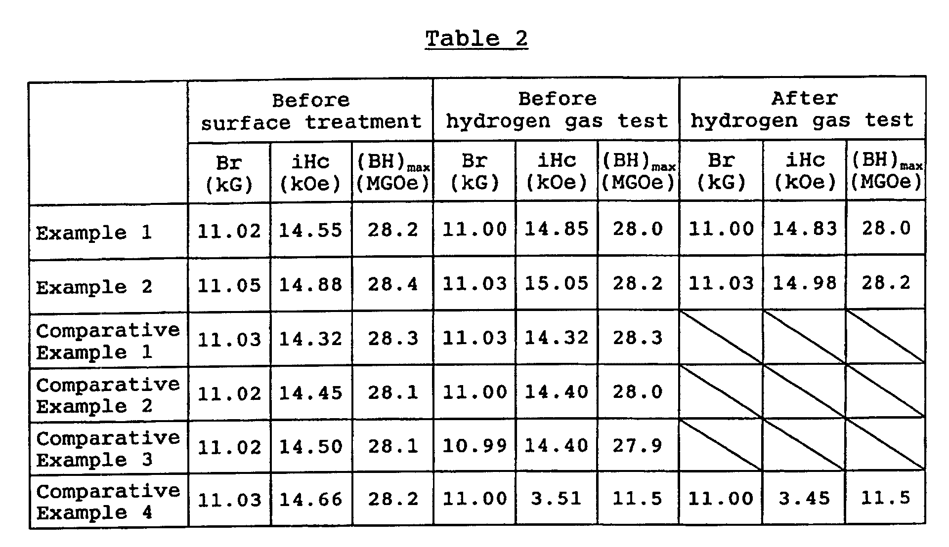
  • Table 2 shows the magnetic properties of the magnets before surface treatment and before and after the hydrogen gas test.
  • the magnetic properties of the magnets remained substantially unchanged before surface treatment and before and after the hydrogen gas test.
  • Comparative Example 4 the magnetic properties of the magnet before surface treatment were very different from those before the hydrogen gas test.
  • FIG. 1 is a reflection electron microscopy image obtained with a scanning electron microscope of the area near the surface of the magnet produced in Example 3 by covering a rare-earth sintered magnet with a 15 ⁇ m layer of plated nickel, then heat-treating at 600°C for 24 hours in air. A nickel oxide layer having a thickness of about 10 ⁇ m can be seen on the surface.
  • Example 3 the hydrogen gas test specimens were subjected to the same hydrogen gas test. Following the test, the magnets were removed, their appearance was visually checked, and their magnetic properties were measured with a VSM.
  • Sintered magnets were produced in the same composition and by the same method as in Example 3. As in Example 3, magnets measuring 5 ⁇ 5 ⁇ 5 mm were cut from the resulting sintered magnets. A 15 ⁇ m layer of nickel was electroplated onto the resulting magnets under the same conditions as in Example 3, in addition to which the magnets were coated by spraying on an epoxy resin to give hydrogen gas test specimens. The microstructure of the resulting test specimens was examined with a scanning electron microscope, and their magnetic properties were measured with a VSM. As in Example 3, the hydrogen gas test specimens were subjected to the same hydrogen gas test. Following the test, the magnets were removed and their appearance was visually checked.
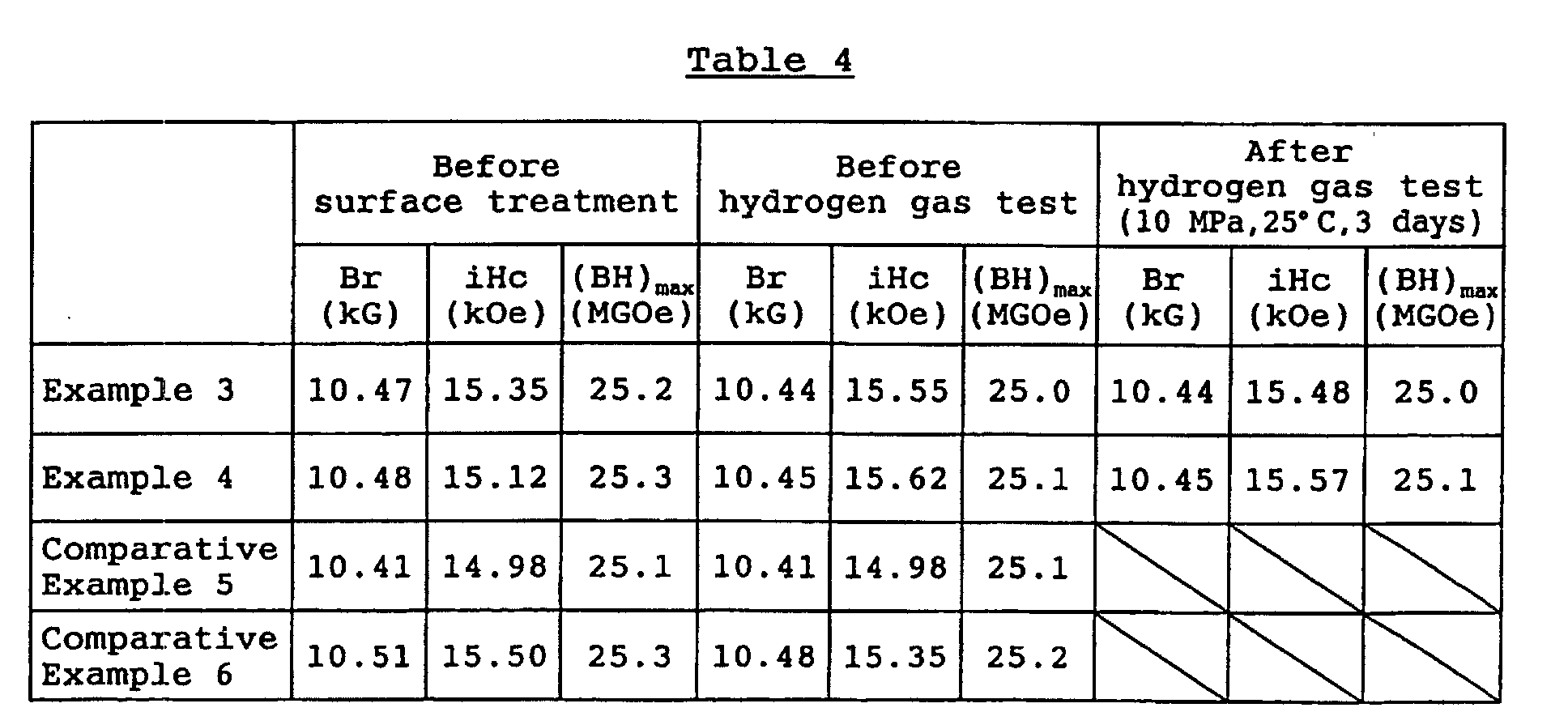
  • Table 4 shows the magnetic properties of the magnets before surface treatment and before and after the hydrogen gas test.
  • the magnetic properties of the magnets remained substantially unchanged before surface treatment and before and after the hydrogen gas test. These results indicate the absence in Examples 3 and 4 of deterioration in magnetic properties due to surface treatment, and the absence of hydrogen embrittlement.
  • Comparative Example 5 and 6 the magnets disintegrated as a result of hydrogen treatment, making it impossible to measure the magnetic properties following hydrogen treatment.
  • the heat-treated magnets were slowly cooled to room temperature, then coated by spraying on an epoxy resin to give hydrogen gas test specimens.
  • the magnetic properties of the test specimens were measured with a VSM.
  • the hydrogen gas test specimens were subjected to a hydrogen gas test under the same conditions as in Example 5, then removed from the pressure vessel. Following removal, the appearance of each magnet was visually checked and its magnetic properties were measured with a VSM.
  • a R 2 Fe 14 B-based magnet alloy was produced by formulating a starting material containing 29.0 wt% of neodymium, 3.0 wt% of dysprosium, 3.5 wt% of cobalt, 1.0 wt% of boron, 0.1 wt% of copper and 0.1 wt% of aluminum, with the balance being iron.
  • the starting material was placed in an alumina crucible and melted in an induction melting furnace under an argon atmosphere, then cast in a mold.
  • a 10 ⁇ m layer of copper and a 10 ⁇ m layer of nickel were electroplated in this order onto the resulting magnets.
  • Copper electroplating was carried out using a plating bath adjusted to concentrations of 60 g/L copper pyrophosphate, 240 g/L potassium pyrophosphate and 30 g/L potassium oxalate, and at a bath temperature of 40°C and a current density of 1.5 A/dm 2 .
  • nickel electroplating was carried out using a plating bath adjusted to concentrations of 40 g/L nickel chloride, 270 g/L nickel sulfate and 30 g/L boric acid, and at a bath temperature of 50°C and a current density of 2.0 A/dm 2 .
  • the plated magnets were subsequently heat treated at 350°C for 50 hours in air, then slowly cooled to room temperature, yielding hydrogen gas test specimens.
  • the microstructure of the resulting hydrogen gas test specimens was examined with a scanning electron microscope.
  • the metal plating metal was found to have formed an oxide, and the thickness of this oxide top layer was measured.
  • the magnetic properties of the test specimens were measured with a VSM.
  • Sintered magnets were produced in the same composition and by the same method as in Example 7. As in Example 7, magnets measuring 5 ⁇ 5 ⁇ 5 mm were cut from the resulting sintered magnets. A 10 ⁇ m layer of copper and a 10 ⁇ m layer of nickel were electroplated in this order onto the resulting magnets under the same conditions as in Example 7. The plated magnets were heat treated at 300°C for 2 hours in air, then slowly cooled to room temperature, yielding hydrogen gas test specimens. The microstructure of the resulting test specimens was examined with a scanning electron microscope, and the thickness of the metal plating metal oxide layer was measured. The magnetic properties of the test specimens were measured with a VSM.

Landscapes

  • Engineering & Computer Science (AREA)
  • Power Engineering (AREA)
  • Chemical & Material Sciences (AREA)
  • Crystallography & Structural Chemistry (AREA)
  • Inorganic Chemistry (AREA)
  • Environmental & Geological Engineering (AREA)
  • Manufacturing & Machinery (AREA)
  • Organic Chemistry (AREA)
  • Metallurgy (AREA)
  • Mechanical Engineering (AREA)
  • Materials Engineering (AREA)
  • Hard Magnetic Materials (AREA)
  • Manufacturing Cores, Coils, And Magnets (AREA)
  • Powder Metallurgy (AREA)

Abstract

Hydrogen embrittlement is prevented in Sm2Co17-based magnets and R2Fe14B-based magnets by metal plating the magnet, then carrying out heat treatment, or by forming a metal oxide or metal nitride layer on the metal plating layer or directly on the magnet itself.

Description

TECHNICAL FIELD
The present invention relates to rare-earth sintered magnets which can be used in devices such as motors exposed for a long period of time to a hydrogen atmosphere. The invention also relates to a method of manufacturing such magnets.
BACKGROUND ART
Intermetallic compounds of rare-earth elements and transition metals have an ability to allow hydrogen to infiltrate into their crystal lattice, that is, the ability to store and release hydrogen in and out of the alloy. This property is employed in a variety of applications, such as hydrogen cells that make use of hydrogen storage alloys as typified by LaNi5. In rare-earth sintered magnet-related applications, the same property is used as a size reduction method for R2Fe14B-based alloys, and in the hydrogenation disproportionation desorption recombination (HDDR) process for producing R2Fe14B-based bonded magnets (JP-A 3-129702).
However, hydrogen storage and release in an alloy or magnet causes hydrogen embrittlement. Thus, when a motor or other device that uses a rare-earth sintered magnet is employed in a hydrogen atmosphere, the rare-earth sintered magnet undergoes hydrogen embrittlement, resulting in breaking, cracking or powdering of the magnet material.
Currently available rare-earth sintered magnets include R2Fe14B-based, SmCo5-based and Sm2Co17-based magnets. Generally, a 1:5 crystal structure has a lower plateau pressure for hydrogen than a 2:17 crystal structure, and a 2:7 crystal structure has a lower plateau pressure than a 1:5 crystal structure. Thus, a rare earth-rich (abbreviated below as "R-rich") alloy tends to retain hydrogen more easily and to be more readily subject to hydrogen embrittlement.
R2Fe14B-based magnets have a R-rich phase in the magnet, as a result of which they readily undergo hydrogen embrittlement in hydrogen atmospheres at pressures of 0.1 MPa or less, leading to breaking, cracking or degradation of the magnet material. R2Fe14B-based magnets are usually given a surface treatment, such as plating or resin coating, to improve corrosion resistance, although such treatment is not a means for preventing hydrogen embrittlement. A solution is proposed in JP-A 2000-285415, which describes a method for including a hydrogen storage alloy in the surface treatment film on R2Fe14B-based magnets. R2Fe14B-based magnets produced by this method do not undergo hydrogen embrittlement in hydrogen atmospheres at pressures of 0.1 MPa or less, but they apparently undergo hydrogen embrittlement in hydrogen atmospheres at higher pressures than this, leading to breaking, cracking or degradation of the magnet material.
SmCo5-based magnets, like R2Fe14B-based magnets, have a R-rich phase. In addition, the SmCo5 phase, which is the main phase, has a plateau pressure of about 0.3 MPa. Hence, in a hydrogen atmosphere at a pressure higher than 0.3 MPa, hydrogen embrittlement occurs, resulting in breaking, cracking or degradation of the magnet material.
In Sm2Co17-based magnets, the main phase is a 2:17 phase. Unlike R2Fe14B-based magnets and SmCo5-based magnets, Sm2Co17-based magnets are not R-rich and do not contain an R-rich phase. Hence, they are not readily subject to hydrogen embrittlement. However, in hydrogen atmospheres at pressures higher than 1 MPa, Sm2Co17-based magnets too, like the other types of rare-earth sintered magnets mentioned above, undergo hydrogen embrittlement, resulting in breaking, cracking or degradation of the magnet material.
DISCLOSURE OF THE INVENTION
The object of the invention is to provide rare-earth sintered magnets and methods of manufacture thereof which resolve the problem of hydrogen embrittlement that occurs in prior-art rare-earth sintered magnets within a hydrogen atmosphere, and the resulting breaking, cracking or degradation of the magnet material.
To enhance the resistance to hydrogen embrittlement, we earlier proposed, in JP-A 2002-118009, a process wherein a Sm2Co17-based sintered magnet is surface-machined by cutting and/or grinding, then heat-treated in an atmosphere having an oxygen partial pressure of from 1×10⁻⁶ to 152 torr, or wherein a microdispersed Sm2O3-containing layer of cobalt and/or cobalt and iron is provided on the surface of a Sm2Co17-based magnet. When a microdispersed Sm2O3-containing layer of cobalt and/or cobalt and iron is provided on the magnet surface, hydrogen embrittlement does not arise even in a high-pressure hydrogen atmosphere having a pressure higher than 3 MPa. However, because the Sm2Co17-based magnet and the microdispersed Sm2O3-containing layer of cobalt and/or cobalt and iron are hard and fragile, they tend to chip when handled, such as during product assembly. Although damage such as chipping has substantially no effect on the magnetic properties of rare-earth sintered magnets, it has a large effect on the resistance of the magnet to hydrogen embrittlement, reducing such resistance to the same level as that of a magnet having no surface layer.
Therefore, in hydrogen atmospheres at pressures higher than 1 MPa, hydrogen embrittlement occurs, leading to breaking, cracking or degradation of the magnet material. Use in such an atmosphere is thus impossible.
The cause of the above problem is the low mechanical strength of Sm2Co17-based magnets. The hydrogen resistance can be maintained if a mechanical strength of Sm2Co17-based magnet is improved or chipping is prevented. R2Fe14B-based magnets have a higher mechanical strength than Sm2Co17-based magnets, in addition to which they generally have a non-oxidizable surface film. As a result, they are less likely to incur damage such as chipping. Covering a R2Fe14B-based magnet with a hydrogen-resistant film would thus appear to be an effective solution.
Although R2Fe14B-based magnets have a number of drawbacks compared with Sm2Co17-based magnets, such as a lower corrosion resistance and inferior temperature properties, the principal elements are neodymium and iron, both of which are inexpensive, rather than the expensive elements samarium and cobalt. Hence, the starting material costs are low. Moreover, with regard to the highest magnetic properties of rare-earth sintered magnets currently in mass production, R2Fe14B-based magnets have a maximum energy product of 50 MGOe, which is larger than the maximum energy product of 32 MGOe for Sm2Co17-based magnets. Once they have been surface-treated to improve their corrosion resistance, R2Fe14B-based magnets are outstanding permanent magnet materials at ambient temperatures. In applications where excellent temperature properties are not required or where the magnet is not subjected to temperatures above 150°C, R2Fe14B-based magnets are commonly used in place of Sm2Co17-based magnets to provide magnetic circuits of smaller size and higher efficiency. It is thus evident that, were R2Fe14B-based magnets to have hydrogen resistance, their magnetic properties would make them much more effective than Sm2Co17-based magnets.
In light of the above circumstances, we have conducted extensive investigations to achieve the foregoing aims. As a result, we have discovered a method of manufacturing rare-earth sintered magnets that do not undergo hydrogen embrittlement even in a high-pressure hydrogen atmosphere. The method involves surface machining a sintered and aged magnet, then metal-plating the surface-machined magnet and subjecting it to optimal heat treatment so as to form on the surface of the magnet a layer of excellent hydrogen resistance. We have found that Sm2Co17-based sintered magnets and R2Fe14B-based sintered magnets highly suitable for use in devices such as motors exposed for long periods of time to a hydrogen atmosphere can be obtained in this way.
Moreover, we have also discovered that forming a metal oxide layer and/or a metal nitride layer on the surface of a Sm2Co17-based or R2Fe14B-based sintered magnet, either directly or over an intervening metal-plating layer, keeps hydrogen embrittlement from arising even in a high-pressure hydrogen atmosphere. There can thus be obtained Sm2Co17-based or R2Fe14B-based sintered magnets highly suitable for use in devices such as motors exposed for long periods of time to a hydrogen atmosphere.
Accordingly, the invention provides the following rare-earth sintered magnets and methods of manufacture thereof.
  • (1) A method of manufacturing rare-earth sintered magnets, characterized by subjecting an alloy composed of 20 to 30 wt% of a constituent R (R being samarium alone or at least 50 wt% samarium in combination with one or more other rare-earth element), 10 to 45 wt% iron, 1 to 10 wt% copper and 0.5 to 5 wt% zirconium, with the balance being cobalt and inadvertent impurities, to the steps of, in order, melting, casting, coarse size reduction, milling, molding in a magnetic field, sintering and aging so as to form a sintered magnet, surface machining the sintered magnet by cutting and/or grinding, metal plating the surface-machined magnet, then heat treating the metal-plated magnet at 80 to 850°C for a period of from 10 minutes to 50 hours.
  • (2) A rare-earth sintered magnet composed of 20 to 30 wt% of a constituent R (R being samarium alone or at least 50 wt% samarium in combination with one or more other rare-earth element), 10 to 45 wt% iron, 1 to 10 wt% copper and 0.5 to 5 wt% zirconium, with the balance being cobalt and inadvertent impurities, which rare-earth sintered magnet is characterized by having on a surface thereof, either directly or over an intervening metal-plating layer, a metal oxide layer and/or a metal nitride layer.
  • (3) A method of manufacturing rare-earth sintered magnets, characterized by subjecting an alloy composed of 20 to 35 wt% of a constituent R (R being one or more rare-earth element selected from among neodymium, praseodymium, dysprosium, terbium and holmium), up to 15 wt% cobalt, 0.2 to 8 wt% boron, and up to 8 wt% of one or more element selected from among nickel, niobium, aluminum, titanium, zirconium, chromium, vanadium, manganese, molybdenum, silicon, tin, gallium, copper and zinc as an additive, with the balance being iron and inadvertent impurities, to the steps of, in order, melting, casting, coarse size reduction, milling, molding in a magnetic field, sintering and heat treatment to form a sintered magnet, surface machining the sintered magnet by cutting and/or grinding, metal plating the surface-machined magnet, then heat treating the metal-plated magnet at 80 to 700°C for a period of from 10 minutes to 50 hours.
  • (4) A rare-earth sintered magnet composed of 20 to 35 wt% of a constituent R (R being one or more rare-earth element selected from among neodymium, praseodymium, dysprosium, terbium and holmium), up to 15 wt% cobalt, 0.2 to 8 wt% boron, and up to 8 wt% of one or more element selected from among nickel, niobium, aluminum, titanium, zirconium, chromium, vanadium, manganese, molybdenum, silicon, tin, gallium, copper and zinc as an additive, with the balance being iron and inadvertent impurities, which rare-earth sintered magnet is characterized by having on a surface thereof, either directly or over n metal-plating layers (n being an integer such that n ≥ 1), a metal oxide layer and/or a metal nitride layer.
  • BRIEF DESCRIPTION OF THE DRAWINGS
  • FIG. 1 is a reflection electron microscopy image obtained with a scanning electron microscope of the area near the surface of the magnet produced in Example 3 by covering a rare-earth sintered magnet with a 15 µm layer of plated nickel, then heat-treating at 600°C for 24 hours in air.
  • FIG. 2 is a reflection electron microscopy image obtained with a scanning electron microscope of the area near the surface of the magnet produced in Example 4 by covering a rare-earth sintered magnet with a 15 µm layer of plated nickel, then heat-treating at 500°C for 2 hours in air.
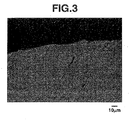
  • FIG. 3 is a reflection electron microscopy image obtained with a scanning electron microscope of the area near the surface of the magnet produced in Comparative Example 6 by covering a rare-earth sintered magnet with a 15 µm layer of plated nickel.
  • BEST MODE FOR CARRYING OUT THE INVENTION Sm2Co17-Based Sintered Magnet Alloy
    The Sm2Co17-based sintered magnet alloy used in the invention is composed primarily of 20 to 30 wt% of a rare-earth constituent which is samarium alone or at least 50 wt% samarium in combination with at least one other rare-earth element, 10 to 45 wt% of iron, 1 to 10 wt% of copper and 0.5 to 5 wt% of zirconium, with the balance being cobalt and inadvertent impurities. Illustrative, non-limiting examples of the above rare-earth elements other than samarium include neodymium, cesium, praseodymium and gadolinium. Magnets having effective magnetic properties are not obtained when the samarium content of the rare-earth constituent in the alloy is less than 50 wt%, or when the alloy has a rare-earth element content of less than 20 wt% or more than 30 wt%.
    R2Fe14B-Based Sintered Magnet Alloy
    The R2Fe14B-based sintered magnet alloy used in the invention is composed primarily of 20 to 35 wt% of a constituent R (R being one or more rare-earth element selected from among neodymium, praseodymium, dysprosium, terbium and holmium), more than 0 wt% and up to 15 wt% of cobalt, 0.2 to 8 wt% of boron, and more than 0 wt% and up to 8 wt% of at least one element selected from among nickel, niobium, aluminum, titanium, zirconium, chromium, vanadium, manganese, molybdenum, silicon, tin, gallium, copper and zinc as an additive, with the balance being iron and inadvertent impurities. At a constituent R content lower than 20 wt%, magnets obtained from the alloy have a markedly diminished coercivity. At a constituent R content higher than 35 wt%, magnets obtained from the alloy have a markedly diminished residual flux density.
    First Method of the Invention
    The first method of the invention is characterized by subjecting a magnet alloy of the above-indicated composition to the steps of, in order, melting, casting, coarse size reduction, milling, molding in a magnetic field, sintering and heat treatment so as to form a sintered magnet. Next, the sintered magnet is surface-machined by cutting and/or grinding, then metal plated, after which the metal-plated magnet is heat treated at 80 to 850°C for a period of from 10 minutes to 50 hours.
    Describing the process more specifically, a Sm2Co17- or R2Fe14B-based sintered magnet alloy according to the invention is prepared by induction melting a starting material having a composition within the above-indicated ranges in a non-oxidizing atmosphere such as argon, then casting the molten material.
    Next, the Sm2Co17-based or R2Fe14B-based magnet alloy is subjected to coarse size reduction, then milled to an average particle size of preferably 1 to 10 µm, and most preferably about 5 µm. Coarse size reduction can be carried out in an inert gas atmosphere by means of, for example, a jaw crusher, a Braun mill, a pin mill or hydrogen occlusion. Milling can be carried out, for example, in a wet ball mill using a solvent such as alcohol or hexane, in a dry ball mill under an inert gas atmosphere, or in a jet mill using a stream of inert gas.
    Next, in the production of Sm2Co17-based magnets, the milled powder is compression molded such as with a magnetic field-generating press capable of applying a magnetic field of preferably at least 10 kOe, and most preferably at least 15 kOe, and under an applied pressure of preferably at least 500 kg/cm2 but less than 2,000 kg/cm2. The resulting powder compact is sintered and solution treated with a heat treatment furnace in a non-oxidizing gas atmosphere such as argon at a temperature 1100 to 1300°C, and preferably 1150 to 1250°C, for a period of 0.5 to 5 hours. Following completion of these steps, the sintered and solution-treated compact is quenched. Next, the compact is subjected to aging treatment in which it is held in an argon atmosphere at a temperature of 700 to 900°C, and preferably 750 to 850°C, for a period of 5 to 40 hours, then gradually cooled to 400°C at a rate of -1.0°C/min. The compact is then surface-machined and finished by cutting and/or grinding. It is desirable, though not essential, to chamfer the edges of the rare-earth sintered magnet at this time.
    In the production of R2Fe14B-based magnets, the milled powder is compression molded such as with a magnetic field-generating press capable of applying a magnetic field of preferably at least 10 kOe, and most preferably at least 15 kOe, under an applied pressure of preferably at least 200 kg/cm2 but less than 2,000 kg/cm2. The resulting powder compact is sintered with a heat treatment furnace in a high vacuum or a non-oxidizing gas atmosphere such as argon at a temperature of 1000 to 1200°C for a period of 1 to 2 hours. Next, the compact is heat-treated in a vacuum or a non-oxidizing gas atmosphere such as argon, at a temperature lower than the sintering temperature, and preferably 400 to 700°C, then surface-machined and finished by cutting and/or grinding. It is desirable time to chamfer the edges of the rare-earth sintered magnet at this time.
    After the rare-earth sintered magnet has been surface-machined, a metal plating layer is formed thereon. The higher the number of metal plating layers, the better the resulting corrosion resistance. However, given that more layers results in higher production costs, lower production efficiency and diminished magnetic properties, the number of such layers may be set at 1 to 5 layers and, in the case of R2Fe14B-based magnets in particular, 2 to 5 layers. The number of layers is preferably selected on the basis of such considerations as the corrosion resistance required of the intended application. The metal-plating metal is preferably one or more selected from among copper, nickel, cobalt, tin, and alloys thereof. The plating thickness is preferably 1 to 100 µm, and most preferably 1 to 50 µm. Preferred multilayer platings include those composed of a copper bottom layer followed by one or more nickel layer, such as Cu-Ni, Cu-Ni-Ni, and Ni-Cu-Ni.
    No particular limitation is imposed on pretreatment for such metal plating, although it is preferable for the rare-earth sintered magnet prior to plating to be alkali cleaned, acid cleaned, and rinsed with water. The plating coat-forming method is not subject to any particular limitation, although electroplating is preferred. Immersion of the rare-earth sintered magnet in the plating solution may be carried out by a barrel process or a rack process, suitable selection of the process used being made in accordance with the dimensions and shape of the rare-earth sintered magnet.
    The electroplating solution used may be a plating solution of a known composition. Plating can be carried out under known conditions for the plating solution, although a plating solution having a pH of 2 to 12 is especially preferred. In cases where metals of differing compositions are deposited as two or more layers, it is desirable for the layer directly beneath the topmost layer to have a corrosion potential which is noble to the topmost layer. In methods where the potential is controlled by varying the sulfur content of the coat, as is done when plating two layers of nickel, it is desirable for the top layer to have a sulfur content of about 0.03% or less and the bottom layer to be sulfur-free. Illustrative, non-limiting examples of other combinations include nickel as the topmost layer in combination with copper as the bottommost layer.
    After metal plating has been carried out by the above method, the magnet is heat-treated in an argon, nitrogen, air or vacuum atmosphere having an oxygen partial pressure of from 1×10⁻⁴ Pa to 50 kPa, and preferably 1×10⁻⁴ Pa to 30 kPa, for a period of from 10 minutes to 50 hours, and at a temperature of 80 to 850°C, preferably 80 to 700°C, and most preferably 200 to 600°C. In the case of R2Fe14B-based magnets, the upper limit in the temperature is preferably 700°C. A heat treatment time of less than 10 minutes is inappropriate because a layer of excellent hydrogen resistance either does not sufficiently form or formation is highly variable. On the other hand, heat treatment for more than 50 hours is inappropriate because it is inefficient and the resulting layer, though having an excellent hydrogen resistance, is so thick as to diminish the magnetic properties of the magnet. At a heat treatment temperature of less than 80°C, a long period of heat treatment is necessary to obtain rare-earth sintered magnets of excellent hydrogen resistance, which is inefficient. On the other hand, at too high a temperature, a layer of excellent hydrogen resistance does form, but the rare-earth sintered magnet and the metal plating react, diminishing the magnetic properties of the magnet. The above-mentioned layer of excellent hydrogen resistance is an oxide layer of the plating metal which has a thickness of preferably 0.1 to 100 µm, and most preferably 0.1 to 20 µm.
    Next, the surface of the rare-earth sintered magnet may be resin coated by a technique such as spray coating, electrodeposition coating, powder coating or dip coating. The resin coat thus obtained does not have hydrogen resistance. Rather, it is formed in cases where, depending on the working atmosphere of the motor or other device in which the rare-earth sintered magnet is used, the magnet may need to be acid-resistant, and to prevent scratching of the surface layer on the magnet when it is installed in a motor or other device. The resin used in resin coating is not subject to any particular limitation. Desirable examples include acrylic, epoxy, phenolic, silicone, polyester and polyurethane-based resins.
    Second Method of the Invention
    In the second method of the invention, a metal oxide layer and/or metal nitride layer is formed on the surface of a Sm2Co17-based or R2Fe14B-based sintered magnet, either directly or over an intervening metal plating layer.
    More specifically, the Sm2Co17-based or R2Fe14B-based sintered magnet of the invention is a rare-earth sintered magnet of the above-described composition having on the surface thereof a metal oxide layer and/or metal nitride layer, either directly on the magnet surface or over n intervening metal-plating layers (n being an integer such that n ≥ 1, preferably 5 ≥ n ≥ 1 and, particularly in the case of R2Fe14B-based sintered magnets, most preferably 5 ≥ n ≥ 2), which effectively prevents hydrogen embrittlement from arising.
    The metal oxide layer and metal nitride layer may be formed directly on the magnet surface by any of various vapor phase plating techniques, or may be formed by any of various vapor phase plating techniques after first forming a metal plating layer on the magnet surface. Alternatively, a metal plating layer may be formed, following which at least the surface of the metal plating layer may be oxidized and/or nitrided such as by heating in an air or other oxidizing atmosphere or in a nitrogen atmosphere. In the latter case, the entire metal plating layer that has formed may be oxidized and/or nitrided.
    In this case, the metal plating layer does not have hydrogen resistance. Rather, it is applied to enhance the impact resistance of Sm2Co17 sintered magnets, which have a low mechanical strength and are prone to chipping and other damage, or to enhance the corrosion resistance of R2Fe14B-based magnets, which have a low corrosion resistance.
    The metal plating layer and the metal oxide layer and/or metal nitride layer have a combined thickness of preferably at least 1 µm but not more than 100 µm. The thickness of the topmost metal oxide layer and/or metal nitride layer is preferably at least 0.1 µm but not more than 100 µm. The combined thickness of the metal plating layer and the metal oxide layer and/or metal nitride layer is most preferably at least 1 µm but not more than 50 µm, and the thickness of the metal oxide layer and/or metal nitride layer is most preferably at least 0.1 µm but not more than 20 µm. At a combined thickness for the metal plating layer and the metal oxide layer and/or metal nitride layer of more than 100 µm, production tends to be time-consuming, costly, and inefficient. Moreover, such a thickness may adversely impact the magnetic properties of the magnet. On the other hand, a combined thickness of less than 1 µm may be inadequate to improve the impact resistance of the sintered magnet, making it difficult to prevent chipping and other damage. In addition, the metal plating tends to be uneven and have a larger number of pinholes, as a result of which formation of an adequate metal oxide layer and/or a metal nitride layer of excellent hydrogen resistance may not occur. At a thickness of more than 100 µm, the metal oxide layer and/or metal nitride layer does prevent hydrogen embrittlement of the magnet itself, but production tends to be time-consuming, costly, and inefficient. In addition, the very thickness of the layer itself may diminish the magnetic properties of the magnet. At a thickness of less than 0.1 µm, the metal oxide layer and/or metal nitride layer may fail to provide effective resistance to hydrogen embrittlement.
    No particular limitation is imposed on the method of manufacturing sintered magnets having such a metal oxide layer and/or metal nitride layer directly on the surface thereof or over an intervening metal plating layer. However, as in the case described above in connection with the first method of the invention, use is preferably made of a method in which an alloy of the above-described composition is successively cast, subjected to coarse size reduction and also preferably milled, then molded in a magnetic field, sintered and heat-treated to form a sintered magnet. Next, the magnet is typically surface-machined and finished, then metal plated, after which oxidation and/or nitriding treatment is carried out, followed by resin coating.
    After metal plating has been formed in the same way as described above for the first method of the invention, a metal oxide layer and/or metal nitride layer, preferably of the metal in the top metal plating layer, is formed on the resulting metal plating surface. Accordingly, the metal oxide and/or metal nitride is preferably an oxide and/or nitride of copper, nickel, cobalt, tin, or an alloy thereof. Illustrative, non-limiting methods for forming such layers include vapor-phase plating processes such as vacuum deposition, ion sputtering and ion plating, chemical processes, heat treatment in various atmospheres such as an air atmosphere, under oxygen partial pressure regulation, in nitrogen or in pressurized nitrogen, and electrolytic treatment. The metal oxide layer and/or metal nitride layer has a thickness of preferably 0.1 to 100 µm, and most preferably 0.1 to 20 µm.
    As described above for the first method of the invention, the surface of the rare-earth sintered magnet which has been treated in this way can then be resin-coated (e.g., spray-coated, electrodeposition-coated, powder-coated or dip-coated). The resin coat thus obtained does not have hydrogen resistance. Rather, it is formed in cases where, depending on the working atmosphere of the motor or other device in which the rare-earth magnet is used, the magnet may need to be acid-resistant, and to prevent scratching of the surface layer on the magnet during transportation or when it is installed in a motor or other device. The resin used in resin coating is not subject to any particular limitation. Desirable examples include acrylic, epoxy, phenolic, silicone, polyester and polyurethane-based resins. Resin coating is carried out by resin coating techniques such as spray coating, electrodeposition coating, powder coating or dip coating to a resin coat thickness of preferably at least 1 µm but not more than 3 mm, and preferably at least 10 µm but not more than 1 mm. At a thickness of less than 1 µm, uniform coating is not easy. Moreover, a surface layer-protecting effect is difficult to achieve during transportation and when of the rare-earth sintered magnet is installed in a motor or other device. Resin coating to a thickness of more than 3 mm tends to make production time-consuming, costly and inefficient.
    EXAMPLE
    Examples are given below to illustrate the invention, and are not intended to limit the scope thereof.
    Example 1
    A Sm2Co17-based magnet alloy was produced by formulating a starting material containing 25.0 wt% of samarium, 17.0 wt% iron, 4.5 wt% of copper and 2.5 wt% of zirconium, with the balance being cobalt. The starting material was placed in an alumina crucible and melted in an induction melting furnace under an argon atmosphere, then cast in a mold.
    The resulting Sm2Co17-based magnet alloy was reduced to a size of about 500 µm or less with a jaw crusher and a Braun mill, after which it was milled to an average particle size of about 5 µm with a jet mill using a stream of nitrogen. The milled powder was molded with a magnetic field-generating press under a pressure of 1.5 t/cm2 within a magnetic field of 15 kOe. The resulting powder compacts were sintered in a heat treatment furnace under an argon atmosphere at 1190°C for 2 hours, then solution-treated in argon at 1175° C for 1 hour. Following the completion of solution treatment, the sintered compacts were quenched, then each was held in an argon atmosphere at 800°C for 10 hours and gradually cooled to 400°C at a rate of -1.0°C/min, thereby giving sintered magnets. Magnets measuring 5×5×5 mm were cut from the sintered magnets.
    A 20 µm layer of copper was electroplated onto the resulting magnets using a plating bath adjusted to concentrations of 60 g/L copper pyrophosphate, 240 g/L potassium pyrophosphate and 30 g/L potassium oxalate, and at a bath temperature of 40°C and a current density of 1.5 A/dm2. The plated magnets were subsequently heat treated at 550°C for 12 hours in air (oxygen partial pressure, 20 kPa), slowly cooled to room temperature, then coated by spraying on an epoxy resin, yielding hydrogen gas test specimens. Measurement of the magnetic properties was carried out using a vibrating sample magnetometer (VSM).
    The hydrogen gas test specimens were subjected to a hydrogen gas test in which they were placed in a pressure vessel, sealed within hydrogen at 10 MPa and 25°C and left under these conditions for one day, then removed. Following removal, the appearance of the magnets was visually checked and their magnetic properties were measured with a VSM.
    Example 2
    Sintered magnets were produced in the same composition and by the same method as in Example 1. As in Example 1, magnets measuring 5×5×5 mm were cut from the resulting sintered magnets. A 20 µm layer of copper was electroplated onto the resulting magnets under the same conditions as in Example 1. The plated magnets were heat treated at 550°C for 12 hours in a vacuum (oxygen partial pressure, 1×10⁻² Pa), then slowly cooled to room temperature and subsequently coated by spraying on an epoxy resin, yielding hydrogen gas test specimens. The magnetic properties of the test specimens were measured with a VSM. The hydrogen gas test specimens were subjected to a hydrogen gas test under the same conditions as in Example 1, then removed from the pressure vessel. Following removal, the appearance of the magnets was visually checked and their magnetic properties were measured with a VSM.
    Comparative Example 1
    Sintered magnets were produced in the same composition and by the same method as in Example 1. As in Example 1, magnets measuring 5×5×5 mm were cut from the resulting sintered magnets and coated by spraying on an epoxy resin to give hydrogen gas test specimens. The magnetic properties of the test specimens were measured with a VSM. The hydrogen gas test specimens were subjected to a hydrogen gas test under the same conditions as in Example 1, then removed from the pressure vessel. Following removal, the appearance of the magnets was visually checked.
    Comparative Example 2
    Sintered magnets of the same composition as in Example 1 were produced in the same way as in that example. As in Example 1, magnets measuring 5×5×5 mm were cut from the resulting sintered magnets. A 20 µm layer of copper was electroplated onto the resulting magnets under the same conditions as in Example 1, in addition to which the magnets were coated by spraying on an epoxy resin to give hydrogen gas test specimens. The magnetic properties of the test specimens were measured with a VSM. The hydrogen gas test specimens were subjected to a hydrogen gas test under the same conditions as in Example 1, then removed from the pressure vessel. Following removal, the appearance of the magnets was visually checked.
    Comparative Examples 3 and 4
    Sintered magnets were produced in the same composition and by the same method as in Example 1. As in Example 1, magnets measuring 5×5×5 mm were cut from the resulting sintered magnets. A 20 µm layer of copper was electroplated onto the resulting magnets under the same conditions as in Example 1. In Comparative Example 3, heat treatment was subsequently carried out at 50°C for 12 hours in air (oxygen partial pressure, 20 kPa). In Comparative Example 4, heat treatment was subsequently carried out at 900°C for 12 hours in air (oxygen partial pressure, 20 kPa). In both examples, the heat-treated magnets were slowly cooled to room temperature, then coated by spraying on an epoxy resin to give hydrogen gas test specimens. The magnetic properties of the test specimens were measured with a VSM. The hydrogen gas test specimens were subjected to a hydrogen gas test under the same conditions as in Example 1, then removed from the pressure vessel. Following removal, the appearance of the magnets was visually checked and their magnetic properties were measured with a VSM.
    Surface treatment conditions Hydrogen gas test conditions Appearance after hydrogen gas test Thickness of surface layer
    Example 1 Cu plating (20 µm) + 550° C, 12-hour heat treatment (O2: 20 kPa) 10 MPa
    25° C
    1 day
    no change 5 µm
    Example 2 Cu plating (20 µm) + 550° C, 12-hour heat treatment (O2: 1×10⁻² Pa) no change 1 µm
    Comparative Example 1 not surface treated disintegrated -
    Comparative Example 2 Cu plating (20 µm) disintegrated -
    Comparative Example 3 Cu plating (20 µm) + 50° C, 12-hour heat treatment (O2: 20 kPa) disintegrated not measurable
    Comparative Example 4 Cu plating (20 µm) + 900°C, 12-hour heat treatment (O2: 20 kPa) no change 20 µm
    Table 1 shows the heat treatment conditions, the hydrogen gas test conditions, and the appearance of the magnets following the hydrogen gas test. In Examples 1 and 2 and Comparative Example 4, no change occurred in the hydrogen gas test. However, in Comparative Examples 1, 2 and 3, the magnet disintegrated into small pieces. It is apparent from this that hydrogen embrittlement did not arise in Examples 1 and 2 and Comparative Example 4.
    Figure 00200001
    Table 2 shows the magnetic properties of the magnets before surface treatment and before and after the hydrogen gas test. In Examples 1 and 2 according to the invention, the magnetic properties of the magnets remained substantially unchanged before surface treatment and before and after the hydrogen gas test. By contrast, in Comparative Example 4, the magnetic properties of the magnet before surface treatment were very different from those before the hydrogen gas test. These results indicate the absence in Examples 1 and 2 of deterioration in magnetic properties due to surface treatment and the absence of hydrogen embrittlement. The results also indicate that surface treatment in Comparative Example 4 led to a deterioration in the magnetic properties. In Comparative Examples 1, 2 and 3, the magnets disintegrated as a result of hydrogen treatment, making it impossible to measure the magnetic properties following hydrogen treatment.
    Thus, Tables 1 and 2 show that, in Comparative Examples 1 to 4, surface treatment either led to a clear deterioration in the magnetic properties of the magnets or failed to improve their hydrogen resistance. By contrast, in Examples 1 and 2, surface treatment did not lead to a deterioration in magnetic properties and improved the hydrogen resistance.
    Example 3
    A Sm2Co17-based magnet alloy was produced by formulating a starting material containing 18.0 wt% of samarium, 7.0 wt% of cesium, 14.0 wt% of iron, 4.5 wt% of copper and 2.5 wt% of zirconium, with the balance being cobalt. The starting material was placed in an alumina crucible and melted in an induction melting furnace under an argon atmosphere, then cast in a mold.
    The resulting Sm2Co17-based magnet alloy was reduced to a size of about 500 µm or less with a jaw crusher and a Braun mill, after which it was milled to an average particle size of about 5 µm with a jet mill using a stream of nitrogen. The milled powder was molded with a magnetic field-generating press under a pressure of 1.5 t/cm2 within a magnetic field of 15 kOe. The resulting powder compacts were sintered in a heat treatment furnace under an argon atmosphere at 1170°C for 2 hours, then solution-treated in argon at 1155°C for 1 hour. Following the completion of solution treatment, the sintered compacts were quenched, then each was held in an argon atmosphere at 800°C for 10 hours and gradually cooled to 400°C at a rate of -1.0°C/min, thereby giving sintered magnets. Magnets measuring 5×5×5 mm were cut from the sintered magnets.
    A 15 µm layer of nickel was electroplated onto the resulting magnets using a plating bath adjusted to concentrations of 40 g/L nickel chloride, 270 g/L nickel sulfate and 30 g/L boric acid, and at a bath temperature of 50°C and a current density of 2.0 A/dm2. The plated magnets were subsequently heat treated at 600°C for 24 hours in air (oxygen partial pressure, 20 kPa), slowly cooled to room temperature, then coated by spraying on an epoxy resin, yielding hydrogen gas test specimens. The microstructure of the resulting hydrogen gas test specimens was examined with a scanning electron microscope, and the magnetic properties were measured with a VSM.
    The hydrogen gas test specimens were each placed in a pressure vessel and subjected to a hydrogen gas test under the following conditions: hydrogen, 10 MPa, 25°C, three days. Following the test, the magnets were removed, their appearance was visually checked, and their magnetic properties were measured with a VSM.
    FIG. 1 is a reflection electron microscopy image obtained with a scanning electron microscope of the area near the surface of the magnet produced in Example 3 by covering a rare-earth sintered magnet with a 15 µm layer of plated nickel, then heat-treating at 600°C for 24 hours in air. A nickel oxide layer having a thickness of about 10 µm can be seen on the surface.
    Example 4
    Sintered magnets were produced in the same composition and by the same method as in Example 3. As in Example 3, magnets measuring 5×5×5 mm were cut from the resulting sintered magnets. A 15 µm layer of nickel was electroplated onto the resulting magnets under the same conditions as in Example 3. The plated magnets were heat treated at 500°C for 2 hours in air (oxygen partial pressure, 20 kPa), then slowly cooled to room temperature and subsequently coated by spraying on an epoxy resin, yielding hydrogen gas test specimens. The microstructure of the resulting test specimens was examined with a scanning electron microscope, and the magnetic properties were measured with a VSM.
    As in Example 3, the hydrogen gas test specimens were subjected to the same hydrogen gas test. Following the test, the magnets were removed, their appearance was visually checked, and their magnetic properties were measured with a VSM.
    FIG. 2 is a reflection electron microscopy image obtained with a scanning electron microscope of the area near the surface of the rare-earth sintered magnet produced in Example 4 by covering the magnet with a 15 µm layer of plated nickel, then heat-treating at 500°C for 2 hours in air. A nickel oxide layer having a thickness of about 1 µm can be seen on the surface.
    Comparative Example 5
    Sintered magnets were produced in the same composition and by the same method as in Example 3. As in Example 3, magnets measuring 5×5×5 mm were cut from the resulting sintered magnets, and coated by spraying on an epoxy resin to give hydrogen gas test specimens. The magnetic properties of the test specimens were measured with a VSM. As in Example 3, the hydrogen gas test specimens were subjected to the same hydrogen gas test. Following the test, the magnets were removed and their appearance was visually checked.
    Comparative Example 6
    Sintered magnets were produced in the same composition and by the same method as in Example 3. As in Example 3, magnets measuring 5×5×5 mm were cut from the resulting sintered magnets. A 15 µm layer of nickel was electroplated onto the resulting magnets under the same conditions as in Example 3, in addition to which the magnets were coated by spraying on an epoxy resin to give hydrogen gas test specimens. The microstructure of the resulting test specimens was examined with a scanning electron microscope, and their magnetic properties were measured with a VSM. As in Example 3, the hydrogen gas test specimens were subjected to the same hydrogen gas test. Following the test, the magnets were removed and their appearance was visually checked.
    FIG. 3 is a reflection electron microscopy image obtained with a scanning electron microscope of the area near the surface of the rare-earth sintered magnet produced in Comparative Example 6 by covering the magnet with a 15 µm layer of plated nickel. Unlike in FIGS. 1 and 2, a nickel oxide layer cannot be seen on the surface.
    Surface treatment conditions Hydrogen gas test conditions Appearance after hydrogen
    Example 3 Ni plating (20 µm) + 600°C, 24-hour heat treatment (O2: 20 kPa) 10 MPa
    25°C
    3 days
    no change
    Example 4 Ni plating (20 µm) + 500° C, 2-hour heat treatment (O2: 20 kPa) no change
    Comparative Example 5 not surface treated disintegrated
    Comparative Example 6 Ni plating disintegrated
    Table 3 shows the heat treatment conditions, the hydrogen gas test conditions, and the appearance of the magnets following the hydrogen gas test. In Examples 3 and 4, no change occurred in the hydrogen gas test. However, in Comparative Examples 5 and 6, the magnet disintegrated into small pieces. It is apparent from this that hydrogen embrittlement did not arise in Examples 3 and 4.
    Figure 00240001
    Table 4 shows the magnetic properties of the magnets before surface treatment and before and after the hydrogen gas test. In Examples 3 and 4 according to the invention, the magnetic properties of the magnets remained substantially unchanged before surface treatment and before and after the hydrogen gas test. These results indicate the absence in Examples 3 and 4 of deterioration in magnetic properties due to surface treatment, and the absence of hydrogen embrittlement. In Comparative Example 5 and 6, the magnets disintegrated as a result of hydrogen treatment, making it impossible to measure the magnetic properties following hydrogen treatment.
    The results in Tables 3 and 4 show that, in Comparative Examples 5 and 6, surface treatment failed to improve their hydrogen resistance. By contrast, in Examples 3 and 4, surface treatment did not lead to a deterioration in magnetic properties and improved the hydrogen resistance.
    Example 5
    A R2Fe14B-based magnet alloy was produced by formulating a starting material containing 28.0 wt% of neodymium, 4.0 wt% of dysprosium, 3.5 wt% of cobalt, 1.0 wt% of boron, 0.2 wt% of copper and 0.4 wt% of aluminum, with the balance being iron. The starting material was placed in an alumina crucible and melted in an induction melting furnace under an argon atmosphere, then cast in a mold.
    The resulting R2Fe14B-based magnet alloy was reduced to a size of about 500 µm or less with a jaw crusher and a Braun mill, after which it was milled to an average particle size of about 3 µm with a jet mill using a stream of nitrogen. The milled powder was molded with a magnetic field-generating press under a pressure of 1.2 t/cm2 within a magnetic field of 10 kOe. The resulting powder compacts were sintered in a heat treatment furnace under an argon atmosphere at 1070°C for 2 hours, after which they were cooled and subsequently heat-treated in argon at 600°C for 1 hour, thereby giving sintered magnets. Magnets measuring 5×5×5 mm were cut from the sintered magnets.
    Next, a 5 µm layer of copper, a 5 µm layer of nickel, and a 10 µm layer of nickel were electroplated in this order onto the resulting magnets. Copper electroplating was carried out using a plating bath adjusted to concentrations of 60 g/L copper pyrophosphate, 240 g/L potassium pyrophosphate and 30 g/L potassium oxalate, and at a bath temperature of 40°C and a current density of 1.5 A/dm2. Next, nickel electroplating was carried out using a plating bath adjusted to concentrations of 40 g/L nickel chloride, 270 g/L nickel sulfate and 30 g/L boric acid, and at a bath temperature of 50°C and a current density of 2.0 A/dm2. This was followed by another nickel electroplating step under the same conditions as the first nickel plating step. The plated magnets were subsequently heat treated at 300°C for 50 hours in air (oxygen partial pressure, 20 kPa), slowly cooled to room temperature, then coated by spraying on an epoxy resin, yielding hydrogen gas test specimens. The magnetic properties of the resulting hydrogen gas test specimens were measured with a VSM.
    The hydrogen gas test specimens were each placed in a pressure vessel and subjected to a hydrogen gas test under the following conditions: hydrogen, 10 MPa, 25°C, one day. Following the test, the magnets were removed, their appearance was visually checked, and their magnetic properties were measured with a VSM.
    Example 6
    Sintered magnets were produced in the same composition and by the same method as in Example 5. As in Example 5, magnets measuring 5×5×5 mm were cut from the resulting sintered magnets. A 5 µm layer of copper, a 5 µm layer of nickel and a 10 µm layer of nickel were electroplated onto the resulting magnets in this order under the same conditions as in Example 5. The plated magnets were heat treated at 250°C for 3 hours in a vacuum (oxygen partial pressure, 1×10⁻² Pa), slowly cooled to room temperature, then coated by spraying on an epoxy resin, yielding hydrogen gas test specimens. The magnetic properties of the resulting hydrogen gas test specimens were measured with a VSM. The test specimens were subjected to a hydrogen gas test under the same conditions as in Example 5. Following the test, the magnets were removed, their appearance was visually checked, and their magnetic properties were measured with a VSM.
    Comparative Example 7
    Sintered magnets were produced in the same composition and by the same method as in Example 5. As in Example 5, magnets measuring 5×5×5 mm were cut from the resulting sintered magnets, and coated by spraying on an epoxy resin to give hydrogen gas test specimens. The magnetic properties of the test specimens were measured with a VSM. The hydrogen gas test specimens were subjected to a hydrogen gas test under the same conditions as in Example 5. Following the test, the magnets were removed and their appearance was visually checked.
    Comparative Example 8
    Sintered magnets were produced in the same composition and by the same method as in Example 5. As in Example 5, magnets measuring 5×5×5 mm were cut from the resulting sintered magnets. A 5 µm layer of copper, a 5 µm layer of nickel and a 10 µm layer of nickel were electroplated onto the resulting magnets in this order under the same conditions as in Example 5. The plated magnets were then coated by spraying on an epoxy resin, yielding hydrogen gas test specimens. The magnetic properties of the resulting hydrogen gas test specimens were measured with a VSM. The test specimens were subjected to a hydrogen gas test under the same conditions as in Example 5. Following the test, the magnets were removed and their appearance was visually checked.
    Comparative Examples 9 and 10
    Sintered magnets were produced in the same composition and by the same method as in Example 5. As in Example 5, magnets measuring 5×5×5 mm were cut from the resulting sintered magnets. A 5 µm layer of copper, a 5 µm layer of nickel and a 10 µm layer of nickel were electroplated onto the resulting magnets in this order under the same conditions as in Example 5. In Comparative Example 9, heat treatment was subsequently carried out at 50°C for 12 hours in air (oxygen partial pressure, 20 kPa). In Comparative Example 10, heat treatment was subsequently carried out at 800°C for 12 hours in air (oxygen partial pressure, 20 kPa). In both examples, the heat-treated magnets were slowly cooled to room temperature, then coated by spraying on an epoxy resin to give hydrogen gas test specimens. The magnetic properties of the test specimens were measured with a VSM. The hydrogen gas test specimens were subjected to a hydrogen gas test under the same conditions as in Example 5, then removed from the pressure vessel. Following removal, the appearance of each magnet was visually checked and its magnetic properties were measured with a VSM.
    Surface treatment conditions Hydrogen gas test conditions Appearance after hydrogen gas test Thickness of surface layer
    Example 5 Cu-Ni-Ni plating + 300°C, 50-hour heat treatment (O2: 20 kPa) 10 MPa
    25°C
    1 day
    no change 2 µm
    Example 6 Cu-Ni-Ni plating + 250° C, 3-hour heat treatment (O2: 1×10⁻² Pa) no change 0.5 µm
    Comparative Example 7 not surface treated disintegrated -
    Comparative Example 8 Cu-Ni-Ni plating disintegrated -
    Comparative Example 9 Cu-Ni-Ni plating + 50°C, 12-hour heat treatment (O2: 20 kPa) disintegrated not measurable
    Comparative Example 10 Cu-Ni-Ni plating + 800°C, 12-hour heat treatment (O2: 20 kPa) no change 18 µm
    Table 5 shows the heat treatment conditions, the hydrogen gas test conditions, and the appearance of the magnets following the hydrogen gas test. In Examples 5 and 6 and Comparative Example 10, no change occurred in the hydrogen gas test. However, in Comparative Examples 7, 8 and 9, the magnet disintegrated into small pieces. It is apparent from this that hydrogen embrittlement did not arise in Examples 5 and 6 and Comparative Example 10.
    Figure 00300001
    Table 6 shows the magnetic properties of the magnets before surface treatment and before and after the hydrogen gas test. In Examples 5 and 6 according to the invention, the magnetic properties of the magnets remained substantially unchanged before surface treatment and before and after the hydrogen gas test. By contrast, in Comparative Example 10, the magnetic properties of the magnet before surface treatment were very different from those before the hydrogen gas test. These results indicate the absence in Examples 5 and 6 of deterioration in magnetic properties due to surface treatment and the absence of hydrogen embrittlement. The results also indicate that surface treatment in Comparative Example 10 led to a deterioration in the magnetic properties. In Comparative Examples 7, 8 and 9, the magnets disintegrated as a result of hydrogen treatment, making it impossible to measure the magnetic properties following hydrogen treatment.
    Thus, Tables 5 and 6 show that, in Comparative Examples 7 to 10, surface treatment either led to a clear deterioration in the magnetic properties of the magnets or failed to improve their hydrogen resistance. By contrast, in Examples 5 and 6, surface treatment did not lead to a deterioration in magnetic properties and improved the hydrogen resistance.
    Example 7
    A R2Fe14B-based magnet alloy was produced by formulating a starting material containing 29.0 wt% of neodymium, 3.0 wt% of dysprosium, 3.5 wt% of cobalt, 1.0 wt% of boron, 0.1 wt% of copper and 0.1 wt% of aluminum, with the balance being iron. The starting material was placed in an alumina crucible and melted in an induction melting furnace under an argon atmosphere, then cast in a mold.
    The resulting R2Fe14B-based magnet alloy was reduced to a size of about 500 µm or less with a jaw crusher and a Braun mill, after which it was milled to an average particle size of about 3 µm with a jet mill using a stream of nitrogen. The milled powder was molded with a magnetic field-generating press under a pressure of 1.2 t/cm2 within a magnetic field of 10 kOe. The resulting powder compacts were sintered in a heat treatment furnace under an argon atmosphere at 1070°C for 2 hours, after which they were cooled and subsequently heat-treated in argon at 600°C for 1 hour, thereby giving sintered magnets. Magnets measuring 5×5×5 mm were cut from the sintered magnets .
    Next, a 10 µm layer of copper and a 10 µm layer of nickel were electroplated in this order onto the resulting magnets. Copper electroplating was carried out using a plating bath adjusted to concentrations of 60 g/L copper pyrophosphate, 240 g/L potassium pyrophosphate and 30 g/L potassium oxalate, and at a bath temperature of 40°C and a current density of 1.5 A/dm2. Next, nickel electroplating was carried out using a plating bath adjusted to concentrations of 40 g/L nickel chloride, 270 g/L nickel sulfate and 30 g/L boric acid, and at a bath temperature of 50°C and a current density of 2.0 A/dm2. The plated magnets were subsequently heat treated at 350°C for 50 hours in air, then slowly cooled to room temperature, yielding hydrogen gas test specimens. The microstructure of the resulting hydrogen gas test specimens was examined with a scanning electron microscope. The metal plating metal was found to have formed an oxide, and the thickness of this oxide top layer was measured. The magnetic properties of the test specimens were measured with a VSM.
    The hydrogen gas test specimens were each placed in a pressure vessel and subjected to a hydrogen gas test under the following conditions: hydrogen, 5 MPa, 25°C, three days. Following the test, the magnets were removed, their appearance was visually checked, and their magnetic properties were measured with a VSM.
    Example 8
    Sintered magnets were produced in the same composition and by the same method as in Example 7. As in Example 7, magnets measuring 5×5×5 mm were cut from the resulting sintered magnets. A 10 µm layer of copper and a 10 µm layer of nickel were electroplated in this order onto the resulting magnets under the same conditions as in Example 7. The plated magnets were heat treated at 300°C for 2 hours in air, then slowly cooled to room temperature, yielding hydrogen gas test specimens. The microstructure of the resulting test specimens was examined with a scanning electron microscope, and the thickness of the metal plating metal oxide layer was measured. The magnetic properties of the test specimens were measured with a VSM.
    As in Example 7, the hydrogen gas test specimens were each placed in a pressure vessel and subjected to the same hydrogen gas test. Following the test, the magnets were removed, their appearance was visually checked, and their magnetic properties were measured with a VSM.
    Comparative Example 11
    Sintered magnets were produced in the same composition and by the same method as in Example 7. As in Example 7, magnets measuring 5×5×5 mm were cut from the resulting sintered magnets, giving hydrogen gas test specimens. The magnetic properties of the test specimens were measured with a VSM. As in Example 7, the hydrogen gas test specimens were subjected to the same hydrogen gas test. Following the test, the magnets were removed and their appearance was visually checked.
    Comparative Example 12
    Sintered magnets were produced in the same composition and by the same method as in Example 7. As in Example 7, magnets measuring 5×5×5 mm were cut from the resulting sintered magnets. A 10 µm layer of copper and a 10 µm layer of nickel were electroplated in this order onto the resulting magnets under the same conditions as in Example 7, giving hydrogen gas test specimens. The microstructure of the resulting test specimens was examined with a scanning electron microscope, and their magnetic properties were measured with a VSM. As in Example 7, the hydrogen gas test specimens were subjected to the same hydrogen gas test. Following the test, the magnets were removed and their appearance was visually checked.
    Surface treatment conditions Hydrogen gas test conditions Appearance after hydrogen gas test Thickness of surface layer
    Example 7 Cu-Ni plating + 350°C, 50-hour heat treatment in air 5 MPa
    25°C
    3 days
    no change 4 µm
    Example 8 Cu-Ni plating + 300° C, 2-hour heat treatment in air no change 0.5 µm
    Comparative Example 11 not surface treated disintegrated -
    Comparative Example 12 Cu-Ni plating disintegrated -
    Figure 00340001
    Table 8 shows the magnetic properties of the magnets before surface treatment and before and after the hydrogen gas test. In Examples 7 and 8 according to the invention, the magnetic properties of the magnets remained substantially unchanged before surface treatment and before and after the hydrogen gas test. These results indicate the absence in Examples 5 and 6 of deterioration in magnetic properties due to surface treatment and the absence of hydrogen embrittlement. In Comparative Examples 11 and 12, the magnets disintegrated as a result of hydrogen treatment, making it impossible to measure the magnetic properties following hydrogen treatment.
    As is apparent from the results in Tables 7 and 8, the hydrogen gas test gave rise to hydrogen embrittlement in the comparative examples, but did not give rise to hydrogen embrittlement in the examples according to the invention. This shows that surface treatment did not lead to a deterioration in the magnetic properties and enhanced the hydrogen resistance.
    As demonstrated above, the Sm2Co17-based sintered magnets and R2Fe14B-based sintered magnets of the invention are rare-earth sintered magnets which can be used in motors and other devices within a hydrogen atmosphere without undergoing hydrogen embrittlement.

    Claims (12)

    1. A method of manufacturing rare-earth sintered magnets, characterized by subjecting an alloy composed of 20 to 30 wt% of a constituent R (R being samarium alone or at least 50 wt% samarium in combination with one or more other rare-earth element), 10 to 45 wt% iron, 1 to 10 wt% copper and 0.5 to 5 wt% zirconium, with the balance being cobalt and inadvertent impurities, to the steps of, in order, melting, casting, coarse size reduction, milling, molding in a magnetic field, sintering and aging so as to form a sintered magnet, surface machining the sintered magnet by cutting and/or grinding, metal plating the surface-machined magnet, then heat treating the metal-plated magnet at 80 to 850°C for a period of from 10 minutes to 50 hours.
    2. The rare-earth sintered magnet manufacturing method of claim 1, characterized in that the metal-plating metal is one or more selected from among copper, nickel, cobalt, tin, and alloys thereof.
    3. The rare-earth sintered magnet manufacturing method of claim 1 or 2, characterized in that the heat treatment is carried out in an argon, nitrogen, air or low-pressure vacuum atmosphere having an oxygen partial pressure of 10-4 Pa to 50 kPa.
    4. A rare-earth sintered magnet composed of 20 to 30 wt% of a constituent R (R being samarium alone or at least 50 wt% samarium in combination with one or more other rare-earth element), 10 to 45 wt% iron, 1 to 10 wt% copper and 0.5 to 5 wt% zirconium, with the balance being cobalt and inadvertent impurities, which rare-earth sintered magnet is characterized by having on a surface thereof, either directly or over an intervening metal-plating layer, a metal oxide layer and/or a metal nitride layer.
    5. The rare-earth sintered magnet of claim 4, characterized in that the metal-plating layer and the metal oxide layer and/or metal nitride layer have a combined thickness of at least 1 µm but not more than 100 µm, and the metal oxide layer and/or metal nitride layer has a thickness of at least 0.1 µm but not more than 100 µm.
    6. The rare-earth sintered magnet of claim 4 or 5, characterized in that the metal-plating metal is one or more selected from among copper, nickel, cobalt, tin, and alloys thereof.
    7. A method of manufacturing rare-earth sintered magnets, characterized by subjecting an alloy composed of 20 to 35 wt% of a constituent R (R being one or more rare-earth element selected from among neodymium, praseodymium, dysprosium, terbium and holmium), up to 15 wt% cobalt, 0.2 to 8 wt% boron, and up to 8 wt% of one or more element selected from among nickel, niobium, aluminum, titanium, zirconium, chromium, vanadium, manganese, molybdenum, silicon, tin, gallium, copper and zinc as an additive, with the balance being iron and inadvertent impurities, to the steps of, in order, melting, casting, coarse size reduction, milling, molding in a magnetic field, sintering and heat treatment to form a sintered magnet, surface machining the sintered magnet by cutting and/or grinding, metal plating the surface-machined magnet, then heat treating the metal-plated magnet at 80 to 700°C for a period of from 10 minutes to 50 hours.
    8. The method of manufacturing rare-earth sintered magnets according to claim 7, characterized in that the metal-plating metal is one or more selected from among copper, nickel, cobalt, tin, and alloys thereof.
    9. The method of manufacturing rare-earth sintered magnets according to claim 7 or 8, characterized in that heat treatment after the metal plating is carried out in an argon, nitrogen, air or low-pressure vacuum atmosphere having an oxygen partial pressure of 10-4 Pa to 50 kPa.
    10. A rare-earth sintered magnet composed of 20 to 35 wt% of a constituent R (R being one or more rare-earth element selected from among neodymium, praseodymium, dysprosium, terbium and holmium), up to 15 wt% cobalt, 0.2 to 8 wt% boron, and up to 8 wt% of one or more element selected from among nickel, niobium, aluminum, titanium, zirconium, chromium, vanadium, manganese, molybdenum, silicon, tin, gallium, copper and zinc as an additive, with the balance being iron and inadvertent impurities, which rare-earth sintered magnet is characterized by having on a surface thereof, either directly or over n metal-plating layers (n being an integer such that n ≥ 1), a metal oxide layer and/or a metal nitride layer.
    11. The rare-earth sintered magnet of claim 10, characterized in that the metal-plating layer and the metal oxide layer and/or metal nitride layer have a combined thickness of at least 1 µm but not more than 100 µm, and the metal oxide layer and/or metal nitride layer has a thickness of at least 0.1 µm but not more than 100 µm.
    12. The rare-earth sintered magnet of claim 10 or 11, characterized in that the metal-plating metal is one or more selected from among copper, nickel, cobalt, tin, and alloys thereof.
    EP02806069A 2001-12-28 2002-12-24 Rare earth element sintered magnet and method for producing rare earth element sintered magnet Expired - Lifetime EP1467385B1 (en)

    Applications Claiming Priority (9)

    Application Number Priority Date Filing Date Title
    JP2001399175 2001-12-28
    JP2001399174A JP3904061B2 (en) 2001-12-28 2001-12-28 Manufacturing method of rare earth sintered magnet
    JP2001399176 2001-12-28
    JP2001399177A JP3904062B2 (en) 2001-12-28 2001-12-28 Rare earth sintered magnet
    JP2001399176 2001-12-28
    JP2001399175 2001-12-28
    JP2001399174 2001-12-28
    JP2001399177 2001-12-28
    PCT/JP2002/013430 WO2003058648A1 (en) 2001-12-28 2002-12-24 Rare earth element sintered magnet and method for producing rare earth element sintered magnet

    Publications (3)

    Publication Number Publication Date
    EP1467385A1 true EP1467385A1 (en) 2004-10-13
    EP1467385A4 EP1467385A4 (en) 2007-06-27
    EP1467385B1 EP1467385B1 (en) 2010-07-21

    Family

    ID=27482755

    Family Applications (1)

    Application Number Title Priority Date Filing Date
    EP02806069A Expired - Lifetime EP1467385B1 (en) 2001-12-28 2002-12-24 Rare earth element sintered magnet and method for producing rare earth element sintered magnet

    Country Status (7)

    Country Link
    US (1) US7438768B2 (en)
    EP (1) EP1467385B1 (en)
    KR (2) KR100746897B1 (en)
    CN (1) CN1299300C (en)
    DE (1) DE60237114D1 (en)
    TW (1) TWI282101B (en)
    WO (1) WO2003058648A1 (en)

    Cited By (6)

    * Cited by examiner, † Cited by third party
    Publication number Priority date Publication date Assignee Title
    EP2110823A4 (en) * 2007-05-30 2010-05-26 Shinetsu Chemical Co Process for producing highly anticorrosive rare earth permanent magnet and method of using the same
    WO2010091977A1 (en) * 2009-02-10 2010-08-19 Carl Zeiss Smt Ag Actuator having at least one magnet for a projection exposure system, production method therefor and projection exposure system having a magnet
    EP3054466A1 (en) * 2015-02-03 2016-08-10 LG Innotek Co., Ltd. Rare earth magnet and motor including the same
    US10672545B2 (en) 2016-12-06 2020-06-02 Tdk Corporation R-T-B based permanent magnet
    US10672544B2 (en) 2016-12-06 2020-06-02 Tdk Corporation R-T-B based permanent magnet
    CN112017831A (en) * 2020-08-20 2020-12-01 合肥工业大学 Preparation method of high-toughness samarium-cobalt magnet

    Families Citing this family (30)

    * Cited by examiner, † Cited by third party
    Publication number Priority date Publication date Assignee Title
    US7753079B2 (en) * 2005-06-17 2010-07-13 Masco Corporation Of Indiana Magnetic coupling for sprayheads
    US9315975B2 (en) 2005-06-17 2016-04-19 Delta Faucet Company Magnetic coupling for sprayheads
    US7909061B2 (en) 2005-06-17 2011-03-22 Masco Corporation Of Indiana Magnetic coupling for sprayheads
    CN102039407B (en) * 2009-10-14 2014-09-17 三环瓦克华(北京)磁性器件有限公司 Method for decreasing harmful gases in process of sintering sintered neodymium iron boron (NdFeB) magnet
    US8627844B2 (en) * 2009-10-30 2014-01-14 Masco Corporation Of Indiana Magnetic escutcheon mounting assembly
    US8567430B2 (en) * 2009-10-30 2013-10-29 Masco Corporation Of Indiana Magnetic coupling for faucet handle
    EP2624266B1 (en) * 2010-09-30 2020-08-26 Hitachi Metals, Ltd. Method for forming electric copper plating film on surface of rare earth permanent magnet
    EP2523316B8 (en) * 2011-05-11 2014-11-19 ALSTOM Renewable Technologies Generator rotor, assembly method and related insertion tool
    US9284723B2 (en) 2012-07-27 2016-03-15 Kohler Co. Magnetic docking faucet
    US9181685B2 (en) 2012-07-27 2015-11-10 Kohler Co. Magnetic docking faucet
    EP2696219B1 (en) 2012-08-06 2017-01-04 Ampass-Explorer Corp. Header device for improving the reception quality of a material detector device
    CN104637642B (en) * 2015-02-13 2017-03-08 宁波宁港永磁材料有限公司 A kind of SmCo sintered permanent magnet material and preparation method thereof
    CN106024242A (en) * 2016-07-14 2016-10-12 安徽万磁电子有限公司 Corrosion-resistant nickel-plated neodymium-iron-boron raw material powder and preparation method thereof
    CN109841367B (en) * 2017-11-29 2020-12-25 有研稀土新材料股份有限公司 Rare earth bonded magnetic powder, method for producing same, and bonded magnet
    CN109208047A (en) * 2018-08-08 2019-01-15 北京麦戈龙科技有限公司 A kind of coating structure of Sintered NdFeB magnet and preparation method thereof
    US10916269B2 (en) 2019-02-19 2021-02-09 Western Digital Technologies, Inc. Magnet for motor of magnetic storage device
    CN110136908B (en) * 2019-05-07 2021-03-05 宁波科星材料科技有限公司 Rare earth permanent magnet composite material and preparation method thereof
    KR102189985B1 (en) * 2019-10-25 2020-12-11 한국생산기술연구원 Method for manufacturing nd-fe-b group permanent magnet and nd-fe-b group permanent using thereof
    KR102187561B1 (en) * 2019-10-25 2020-12-07 한국생산기술연구원 Method for manufacturing nd-fe-b group permanent magnet containing titanium
    CN111243804B (en) * 2019-11-29 2023-10-17 南京安德海睿智能科技有限公司 Rare earth permanent magnet with hydrogen resistance and preparation method thereof
    CN111313571B (en) * 2019-11-29 2022-01-28 南京安德海睿智能科技有限公司 Hydrogen-resistant motor based on rare earth permanent magnet
    CN111128502B (en) * 2019-12-04 2022-03-25 湖南航天磁电有限责任公司 Preparation method of super-corrosion-resistant high-performance sintered samarium-cobalt magnet
    CN110993235B (en) * 2019-12-26 2020-11-20 福建省长汀卓尔科技股份有限公司 High-iron low-copper samarium-cobalt permanent magnet material and preparation method thereof
    CN111270280B (en) * 2020-01-23 2021-03-30 北京麦戈龙科技有限公司 Coating structure of sintered neodymium-iron-boron magnet and preparation method thereof
    CN113451038B (en) * 2021-06-07 2023-05-02 杭州永磁集团有限公司 Preparation method of samarium cobalt permanent magnet suitable for high-temperature high-pressure pure hydrogen environment
    CN113539606B (en) * 2021-06-16 2023-05-09 杭州永磁集团有限公司 High-temperature-resistant and hydrogen-resistant samarium cobalt permanent magnet motor
    WO2023140753A1 (en) * 2022-01-19 2023-07-27 Общество С Ограниченной Ответственностью "Ампермагнит" Method for manufacturing segmented permanent magnets from low-grade magnetically hard sintered raw material
    US11786835B1 (en) * 2023-04-07 2023-10-17 Shenzhen Huamingjun Rubber Co., Ltd Toy water ball
    IT202400001962A1 (en) * 2024-01-31 2025-07-31 Getters Spa PERMANENT MAGNET COATED WITH NON-EVAPORABLE GETTE
    CN121260662B (en) * 2025-12-08 2026-04-14 包头市英思特稀磁新材料股份有限公司 High-coercivity NdFeB magnet and preparation method thereof

    Family Cites Families (29)

    * Cited by examiner, † Cited by third party
    Publication number Priority date Publication date Assignee Title
    JPS5766604A (en) 1980-10-13 1982-04-22 Toshiba Corp Surface treatment for rare-earth cobalt magnet
    JPS5681908A (en) * 1980-10-14 1981-07-04 Seiko Epson Corp Rare earth metal intermetallic compound sintered magnet having covered surface
    CA1316375C (en) * 1982-08-21 1993-04-20 Masato Sagawa Magnetic materials and permanent magnets
    JPS59161610A (en) 1983-03-03 1984-09-12 Ebara Corp Refuse incinerator
    CN1007847B (en) * 1984-12-24 1990-05-02 住友特殊金属株式会社 Method for manufacturing magnet with improved corrosion resistance
    FI861898A7 (en) * 1986-05-07 1987-11-08 Outokumpu Oy Method for processing metal pieces.
    JP2520450B2 (en) 1988-06-02 1996-07-31 信越化学工業株式会社 Method for manufacturing corrosion resistant rare earth magnet
    JP2576671B2 (en) 1989-07-31 1997-01-29 三菱マテリアル株式会社 Rare earth-Fe-B permanent magnet powder and bonded magnet with excellent magnetic anisotropy and corrosion resistance
    JPH04288804A (en) * 1991-03-18 1992-10-13 Tdk Corp Permanent magnet and manufacture thereof
    JPH05226125A (en) * 1992-02-14 1993-09-03 Kobe Steel Ltd Manufacture of highly corrosion-resistant rare-earth magnet
    US5382303A (en) 1992-04-13 1995-01-17 Sps Technologies, Inc. Permanent magnets and methods for their fabrication
    JPH06108190A (en) * 1992-09-25 1994-04-19 Shin Etsu Chem Co Ltd Rare earth permanent magnet alloy
    JPH06120014A (en) 1992-10-05 1994-04-28 Tokin Corp Surface treatment method for rare earth cobalt magnet alloys
    JPH06140218A (en) * 1992-10-29 1994-05-20 Toshiba Corp Impact resistant rare earth cobalt magnet and method of manufacturing the same
    JPH08181016A (en) 1994-12-22 1996-07-12 Tokin Corp Samarium cobalt magnet and manufacturing method thereof
    US5876518A (en) * 1995-02-23 1999-03-02 Hitachi Metals, Ltd. R-T-B-based, permanent magnet, method for producing same, and permanent magnet-type motor and actuator comprising same
    WO1997023884A1 (en) 1995-12-25 1997-07-03 Sumitomo Special Metals Company Limited Permanent magnet for ultrahigh vacuum application and method for manufacturing the same
    JP2000040610A (en) * 1998-07-24 2000-02-08 Sumitomo Metal Mining Co Ltd Rare earth magnet with coating
    JP3423299B2 (en) * 1998-08-31 2003-07-07 住友特殊金属株式会社 Fe-BR type permanent magnet having corrosion-resistant film
    JP3351768B2 (en) * 1998-08-31 2002-12-03 住友特殊金属株式会社 Method for producing Fe-BR based permanent magnet having corrosion resistant film
    EP0984460B1 (en) 1998-08-31 2004-03-17 Sumitomo Special Metals Co., Ltd. Fe-B-R based permanent magnet having corrosion-resistant film, and process for producing the same
    JP2001076914A (en) * 1998-12-17 2001-03-23 Sumitomo Special Metals Co Ltd Rare-earth based permanent magnet and manufacture thereof
    JP3278647B2 (en) * 1999-01-27 2002-04-30 住友特殊金属株式会社 Rare earth bonded magnet
    JP2000285415A (en) 1999-03-29 2000-10-13 Sumitomo Metal Ind Ltd Method for manufacturing ferromagnetic tunnel junction magnetoresistive element
    JP4529260B2 (en) * 1999-09-27 2010-08-25 日立金属株式会社 R-Fe-B permanent magnet and method for producing the same
    JP4678118B2 (en) * 2000-07-17 2011-04-27 日立金属株式会社 Coated R-T-B magnet and method for manufacturing the same
    JP4081642B2 (en) 2000-07-31 2008-04-30 信越化学工業株式会社 Rare earth sintered magnet and manufacturing method thereof
    US6623541B2 (en) * 2000-07-31 2003-09-23 Shin-Etsu Chemical Co., Ltd. Sintered rare earth magnet and making method
    DE60106695T2 (en) * 2000-08-11 2005-03-31 Neomax Co., Ltd. A rare earth based permanent magnet with a corrosion resistant film and method of making the same

    Cited By (9)

    * Cited by examiner, † Cited by third party
    Publication number Priority date Publication date Assignee Title
    EP2110823A4 (en) * 2007-05-30 2010-05-26 Shinetsu Chemical Co Process for producing highly anticorrosive rare earth permanent magnet and method of using the same
    US8105444B2 (en) 2007-05-30 2012-01-31 Shin-Etsu Chemical Co., Ltd. Process for producing highly anticorrosive rare earth permanent magnet and method of using the same
    WO2010091977A1 (en) * 2009-02-10 2010-08-19 Carl Zeiss Smt Ag Actuator having at least one magnet for a projection exposure system, production method therefor and projection exposure system having a magnet
    US9025128B2 (en) 2009-02-10 2015-05-05 Carl Zeiss Smt Gmbh Actuator including magnet for a projection exposure system and projection exposure system including a magnet
    EP3054466A1 (en) * 2015-02-03 2016-08-10 LG Innotek Co., Ltd. Rare earth magnet and motor including the same
    US10586636B2 (en) 2015-02-03 2020-03-10 Lg Innotek Co., Ltd. Rare earth magnet and motor including the same
    US10672545B2 (en) 2016-12-06 2020-06-02 Tdk Corporation R-T-B based permanent magnet
    US10672544B2 (en) 2016-12-06 2020-06-02 Tdk Corporation R-T-B based permanent magnet
    CN112017831A (en) * 2020-08-20 2020-12-01 合肥工业大学 Preparation method of high-toughness samarium-cobalt magnet

    Also Published As

    Publication number Publication date
    CN1299300C (en) 2007-02-07
    KR100746897B1 (en) 2007-08-07
    KR20040073513A (en) 2004-08-19
    TW200301492A (en) 2003-07-01
    EP1467385A4 (en) 2007-06-27
    WO2003058648A1 (en) 2003-07-17
    CN1618108A (en) 2005-05-18
    EP1467385B1 (en) 2010-07-21
    DE60237114D1 (en) 2010-09-02
    KR20070049245A (en) 2007-05-10
    TWI282101B (en) 2007-06-01
    US7438768B2 (en) 2008-10-21
    US20050028890A1 (en) 2005-02-10
    KR100788330B1 (en) 2007-12-27

    Similar Documents

    Publication Publication Date Title
    US7438768B2 (en) Rare earth element sintered magnet and method for producing rare earth element sintered magnet
    CN1898756B (en) Rare earth magnet
    JP5024531B2 (en) How to use rare earth sintered magnets
    US5082745A (en) Rare earth based permanent magnet having corrosion-resistant surface film and method for the preparation thereof
    JP4003067B2 (en) Rare earth sintered magnet
    JP4003066B2 (en) Manufacturing method of rare earth sintered magnet
    JP2791659B2 (en) Manufacturing method of corrosion resistant permanent magnet
    EP0923087B1 (en) Corrosion-resistant permanent magnet and method for manufacturing the same
    JPH0529119A (en) High corrosion-resistant rare earth magnet
    JPH0945567A (en) Rare earth-iron-boron permanent magnet manufacturing method
    US7740716B2 (en) Rare earth sintered magnet
    JP3904062B2 (en) Rare earth sintered magnet
    US5286366A (en) Surface treatment for iron-based permanent magnet including rare-earth element
    JP4296442B2 (en) Method for preventing hydrogen embrittlement of rare earth sintered magnets
    JPS6377103A (en) Rare-earth magnet excellent in corrosion resistance and manufacture thereof
    JP3914557B2 (en) Rare earth sintered magnet
    JP3904061B2 (en) Manufacturing method of rare earth sintered magnet
    JP2631492B2 (en) Manufacturing method of corrosion resistant permanent magnet
    JP2007288205A (en) Method for improving hydrogen resistance of rare earth sintered magnet
    JP4539288B2 (en) Rare earth sintered magnet
    KR950003859B1 (en) Manufacturing method of corrosion resistant Nd-Fe-B type sintered magnet
    JPH05226125A (en) Manufacture of highly corrosion-resistant rare-earth magnet
    JP2720038B2 (en) Manufacturing method of permanent magnet
    JPH0237702A (en) R-fe-b-m sintered magnet
    JPH0529120A (en) High corrosion-resistant rare earth magnet and manufacture thereof

    Legal Events

    Date Code Title Description
    PUAI Public reference made under article 153(3) epc to a published international application that has entered the european phase

    Free format text: ORIGINAL CODE: 0009012

    17P Request for examination filed

    Effective date: 20040719

    AK Designated contracting states

    Kind code of ref document: A1

    Designated state(s): AT BE BG CH CY CZ DE DK EE ES FI FR GB GR IE IT LI LU MC NL PT SE SI SK TR

    AX Request for extension of the european patent

    Extension state: AL LT LV MK RO

    A4 Supplementary search report drawn up and despatched

    Effective date: 20070529

    RIC1 Information provided on ipc code assigned before grant

    Ipc: H01F 1/057 20060101ALI20070522BHEP

    Ipc: H01F 1/055 20060101AFI20070522BHEP

    Ipc: H01F 41/02 20060101ALI20070522BHEP

    17Q First examination report despatched

    Effective date: 20080610

    GRAP Despatch of communication of intention to grant a patent

    Free format text: ORIGINAL CODE: EPIDOSNIGR1

    GRAS Grant fee paid

    Free format text: ORIGINAL CODE: EPIDOSNIGR3

    GRAA (expected) grant

    Free format text: ORIGINAL CODE: 0009210

    AK Designated contracting states

    Kind code of ref document: B1

    Designated state(s): DE FR GB

    REG Reference to a national code

    Ref country code: GB

    Ref legal event code: FG4D

    REF Corresponds to:

    Ref document number: 60237114

    Country of ref document: DE

    Date of ref document: 20100902

    Kind code of ref document: P

    PLBE No opposition filed within time limit

    Free format text: ORIGINAL CODE: 0009261

    STAA Information on the status of an ep patent application or granted ep patent

    Free format text: STATUS: NO OPPOSITION FILED WITHIN TIME LIMIT

    26N No opposition filed

    Effective date: 20110426

    REG Reference to a national code

    Ref country code: DE

    Ref legal event code: R097

    Ref document number: 60237114

    Country of ref document: DE

    Effective date: 20110426

    REG Reference to a national code

    Ref country code: FR

    Ref legal event code: PLFP

    Year of fee payment: 14

    REG Reference to a national code

    Ref country code: FR

    Ref legal event code: PLFP

    Year of fee payment: 15

    PGFP Annual fee paid to national office [announced via postgrant information from national office to epo]

    Ref country code: FR

    Payment date: 20161111

    Year of fee payment: 15

    Ref country code: GB

    Payment date: 20161221

    Year of fee payment: 15

    GBPC Gb: european patent ceased through non-payment of renewal fee

    Effective date: 20171224

    REG Reference to a national code

    Ref country code: FR

    Ref legal event code: ST

    Effective date: 20180831

    PG25 Lapsed in a contracting state [announced via postgrant information from national office to epo]

    Ref country code: FR

    Free format text: LAPSE BECAUSE OF NON-PAYMENT OF DUE FEES

    Effective date: 20180102

    PG25 Lapsed in a contracting state [announced via postgrant information from national office to epo]

    Ref country code: GB

    Free format text: LAPSE BECAUSE OF NON-PAYMENT OF DUE FEES

    Effective date: 20171224

    PGFP Annual fee paid to national office [announced via postgrant information from national office to epo]

    Ref country code: DE

    Payment date: 20201208

    Year of fee payment: 19

    REG Reference to a national code

    Ref country code: DE

    Ref legal event code: R119

    Ref document number: 60237114

    Country of ref document: DE

    PG25 Lapsed in a contracting state [announced via postgrant information from national office to epo]

    Ref country code: DE

    Free format text: LAPSE BECAUSE OF NON-PAYMENT OF DUE FEES

    Effective date: 20220701