EP1467331A2 - Kassengeldlade - Google Patents
Kassengeldlade Download PDFInfo
- Publication number
- EP1467331A2 EP1467331A2 EP04252072A EP04252072A EP1467331A2 EP 1467331 A2 EP1467331 A2 EP 1467331A2 EP 04252072 A EP04252072 A EP 04252072A EP 04252072 A EP04252072 A EP 04252072A EP 1467331 A2 EP1467331 A2 EP 1467331A2
- Authority
- EP
- European Patent Office
- Prior art keywords
- catch
- drawer
- cash drawer
- cash
- solenoid
- Prior art date
- Legal status (The legal status is an assumption and is not a legal conclusion. Google has not performed a legal analysis and makes no representation as to the accuracy of the status listed.)
- Withdrawn
Links
Images


Classifications
-
- G—PHYSICS
- G07—CHECKING-DEVICES
- G07G—REGISTERING THE RECEIPT OF CASH, VALUABLES, OR TOKENS
- G07G1/00—Cash registers
- G07G1/0018—Constructional details, e.g. of drawer, printing means, input means
- G07G1/0027—Details of drawer or money-box
Definitions
- the present invention relates to cash drawers and more particularly to release mechanisms for cash drawers.
- a known form of cash drawer release mechanism comprises a solenoid which is operated in response to a drawer opening signal received from a cash register or the like to release a catch which holds the drawer closed. The drawer may then open under the force of an opening spring.
- the present invention seeks, from a first aspect to alleviate this problem.
- the present invention provides a cash drawer comprising:
- the catch member is arranged at an angle of up to 45°, and more preferably about 30°, to the base of the cash drawer tray.
- the catch member is pivotally mounted on its support for movement between its first and second positions.
- the catch member and catch support are respective plates, the catch member being mounted on a face of the catch support.
- the catch support is provided with mounting brackets for mounting it at the appropriate angle to the base of the cash tray.
- the catch retainer comprises a tongue of material released from the catch support plate whereby an edge of the catch engages behind the tongue to retain the catch in its closed position.
- the catch disengaging means comprises a solenoid which upon actuation in response to a suitable electric signal, pushes directly or indirectly on the catch member to push it out of engagement with the catch retainer.
- the solenoid is mounted under and preferably projects through the catch support so as to engage the underside of the catch member whereby upon operation of the solenoid the catch member is pushed upwardly out of engagement with the catch retainer.
- the mounting of the catch member on its support comprises a slidable fixing.
- the catch member is mounted pivotally around a shaft along which it can also translate.
- the catch member is biased along the shaft towards its position of engagement by spring means.
- the catch disengagement means preferably comprises a solenoid which is operable in response to an appropriate electrical signal.
- a manual release member extends for engagement with the solenoid to push the catch member in the appropriate direction.
- the manual release member engages the lower end of the movable solenoid part such that it pushes upwardly on the member to release the mechanism.
- This has the advantage that gravity will assist in returning the solenoid to its start position.
- the invention provides a cash drawer mechanism comprising a drawer opening solenoid having a moveable part which is operable to open the cash drawer in response to an opening signal, said cash drawer mechanism further comprising a manual release mechanism, said manual release mechanism operating upon a lower end of the moveable solenoid part so as to move the solenoid member in an opening direction.
- the manual release mechanism comprises an elongate member mounted to the cash drawer for manipulation by a user.
- the manual release member comprises an elongate strip having one end which cooperates with the solenoid.
- the manual release member is mounted adjacent the base of the cash drawer and preferably it extends through the rear of the cash drawer for engagement with the solenoid.
- the manual release member is pivotable to effect the opening movement.
- the release member is preferably pivotally mounted in the cash drawer.
- the manual release member is rotated by a rack and pinion mechanism.
- one end of the release member is provided with a rack into which engages a pinion coupled to a rotary release mechanism accessible by a user, for example a key unit.
- This mechanism has the advantage that it does not impose out of plane forces on the release member and is advantageous in its own right, so from a further aspect, therefore, the invention provides a manual release mechanism for a cash drawer comprising a pivotally mounted release member extending from the front of the cash drawer to a drawer release mechanism at the rear of the drawer, and a rack and pinion mechanism for pivoting the release member in response to a drawer opening action by a user.
- the mechanism is biased towards a closed position by a biasing spring.
- the biasing spring acts on the pinion mechanism, and most preferably extends between the pinion mechanism and a front wall of the drawer.
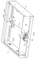
- a cash drawer unit 2 comprises a tray 4 and a drawer 6.
- the drawer 6 is slidable within the tray 4 along guides 8 provided on the sides of the tray.
- the tray is biased to the open condition shown in Figure 1 by spring means not shown.
- the drawer 6 is held in a closed position within the tray 4 by a mechanism 10.
- the mechanism 10 comprises a catch pin 12 mounted in arcuate slots 14 in a pin retaining bracket 16 mounted to the rear face 18 of the drawer 6.
- the other part of the mechanism is a drawer release mechanism 20 which receives the pin 12 when the drawer is in the closed condition and which can release it to allow the drawer to open under its spring loading.
- the arcuate slots 14 allow the pin 12 some degree of movement, to accommodate misalignment of the pin 12 with the release mechanism 20.
- the mechanism comprises a catch 22 which is pivotally mounted to a catch support plate 24 about a spindle 26 mounted to the catch support plate 24.
- the catch support plate 24 has respective legs 28, 30 which have mounting feet 32, 34 at their lower ends.
- the feet 32, 34 have holes 36, 38 for receiving suitable fasteners for fastening the catch support plate 24 to the base of the tray 4 such that it, and thus the catch 22, does not lie parallel to the base of the tray 4. In this particular embodiment it is arranged at an angle of about 30°.
- One leg 28 mounts a drawer status microswitch 40 which is closed when the catch plate 22 is in its closed position indicating that the drawer is closed.
- the other leg 30 mounts a power disconnect microswitch 42 whose operation will be discussed further below.
- the catch 22 is biased to its open position by a spring 44 which engages a mounting post 46 provided on the catch support plate 24 and a lug 48 provided on the catch 22.
- the catch 22 is provided with a hook portion 50 which overlies a slot 52 provided in the catch support plate 24.
- the catch support plate 24 has a raised tongue 54 behind which the catch 22 engages.
- the catch 22 is mounted for both pivotal and axial movement with respect to the spindle 26. In its normal operative condition it is biased downwardly into contact with the catch support plate 24 by a spring 56 and washer 58.
- a solenoid unit 60 is mounted to one leg 28 of the catch support plate 24 and has a moveable member 62 ( Figure 4) whose upper end extends through an aperture 64 in the catch support plate 24 for engagement with the underside of the catch 22.
- the drawer mounted pin 12 engages with the hook 50 so as to retain the drawer closed.
- the pin 12 extends both through the hook 50 and the underlying slot 52 of the catch support plate 24.
- the moveable member 62 moves upwardly to impact on the underside of the catch 22. This pushes the catch 22 upwardly against the force of the spring 56 and out of engagement with the catch retaining tongue 54, so causing the catch 22 to rotate in a clockwise direction in the sense of Figure 3 such that the hook 50 releases the drawer pin 12 to allow the drawer 6 to open.
- the catch 22 is stopped by a lug 66 provided on the catch support plate 24.
- the drawer pin 12 can engage with the edge of the catch 22 so as to pivot it anti-clockwise against the force of the spring 44. Due to the sprung mounting of the catch 22 which allows axial movement of the catch 22 relative to the mounting pin 26, and the inclined face of the catch retaining member 54, the catch 22 will be able to ride up over the catch retaining member 54 until it clears that member 54 and is then forced back down behind it by the spring 56. In that position the hook 50 will have closed once more around the pin 12 to retain the drawer closed, as shown in Figures 2 and 3.
- the drawer described above also has a manual release mechanism 70.
- This mechanism 70 comprises an elongate release member 72 which is mounted along the base 74 of the drawer 6. It extends out through the rear face 18 of the drawer 6.
- the rear end of the member 72 is provided with an opening fitting 76 for engagement with the movable solenoid member 62 as will be described further below.
- the forward end of the member 72 is provided with a rack member 78. Both these members may be an integral part of the opening member 72 or separately fabricated or moulded parts suitably affixed thereto.
- the rack member 78 engages with pinion teeth 80 provided on a lock barrel 82 which can be engaged by a key to open the drawer.
- the release member 72 is pivotally mounted about a pivot (not shown) provided on the base 64 of the drawer 6.
- the release member 72 is biased towards a central, drawer closed, position (intermediate the positions shown in Figures 4 and 5) by a coil spring 84 which extends between a lug 86 on the lock barrel 82 and a mounting hole 88 provided in a flange 90 of the drawer front.
- the opening fitting 76 comprises a cam surface 92 which, when the release member is pivoted towards its opening position, shown in Figure 5, by turning a key inserted into the lock barrel 82, engages the lower end of the moveable solenoid member 62 so as to push it upwardly to disengage the catch member 22 from the catch retaining member 54 thereby allowing the drawer 6 to open.
- the lock barrel 72 may also be turned in an opposite direction from the central, drawer closed, position to a drawer locked position shown in Figure 4. In this position the lock locks the drawer and the opening fitting 76 engages power disconnect microswitch 42 which disables the electrical supply to the solenoid 60, thereby preventing electronic opening of the drawer 4. (In the Figure, the catch 22 is shown disengaged, but it will in fact be engaged in this position.)
Landscapes
- Physics & Mathematics (AREA)
- General Physics & Mathematics (AREA)
- Cash Registers Or Receiving Machines (AREA)
- Drawers Of Furniture (AREA)
Applications Claiming Priority (2)
| Application Number | Priority Date | Filing Date | Title |
|---|---|---|---|
| GB0308007A GB2401143B (en) | 2003-04-07 | 2003-04-07 | Cash drawers |
| GB0308007 | 2003-04-07 |
Publications (2)
| Publication Number | Publication Date |
|---|---|
| EP1467331A2 true EP1467331A2 (de) | 2004-10-13 |
| EP1467331A3 EP1467331A3 (de) | 2007-01-10 |
Family
ID=9956341
Family Applications (1)
| Application Number | Title | Priority Date | Filing Date |
|---|---|---|---|
| EP04252072A Withdrawn EP1467331A3 (de) | 2003-04-07 | 2004-04-07 | Kassengeldlade |
Country Status (2)
| Country | Link |
|---|---|
| EP (1) | EP1467331A3 (de) |
| GB (1) | GB2401143B (de) |
Cited By (4)
| Publication number | Priority date | Publication date | Assignee | Title |
|---|---|---|---|---|
| CN101777228A (zh) * | 2009-12-18 | 2010-07-14 | 江苏银河电子股份有限公司 | 用于检测收银箱中抽屉状态的微动开关的安装结构 |
| CN101630429B (zh) * | 2009-08-12 | 2011-05-25 | 张家港市宏盛电子有限公司 | 收银箱中的锁架及其与电磁铁的安装结构 |
| CN101614086B (zh) * | 2009-07-16 | 2012-05-30 | 张家港市宏盛电子有限公司 | 收银箱中的锁架 |
| EP3697260A4 (de) * | 2017-10-17 | 2021-07-21 | HELMER, Inc. | Untertischkühlschrank mit zugangskontrolle |
Families Citing this family (1)
| Publication number | Priority date | Publication date | Assignee | Title |
|---|---|---|---|---|
| DE50204522D1 (de) | 2002-04-30 | 2005-11-17 | Cognis Ip Man Gmbh | Mit Mikrokapseln ausgerüstete Fasern und textile Flächengebilde |
Citations (1)
| Publication number | Priority date | Publication date | Assignee | Title |
|---|---|---|---|---|
| WO1979000514A1 (en) | 1978-01-18 | 1979-08-09 | Chubb Electronics Ltd | Cash registers |
Family Cites Families (2)
| Publication number | Priority date | Publication date | Assignee | Title |
|---|---|---|---|---|
| DE4332152C2 (de) * | 1993-09-18 | 1996-07-11 | Inkiess Margot Voss Gmbh | Schubladenverriegelung |
| US5723850A (en) * | 1996-07-26 | 1998-03-03 | Loyal Manufacturing Corporation | Cash drawer assembly |
-
2003
- 2003-04-07 GB GB0308007A patent/GB2401143B/en not_active Expired - Fee Related
-
2004
- 2004-04-07 EP EP04252072A patent/EP1467331A3/de not_active Withdrawn
Patent Citations (1)
| Publication number | Priority date | Publication date | Assignee | Title |
|---|---|---|---|---|
| WO1979000514A1 (en) | 1978-01-18 | 1979-08-09 | Chubb Electronics Ltd | Cash registers |
Cited By (5)
| Publication number | Priority date | Publication date | Assignee | Title |
|---|---|---|---|---|
| CN101614086B (zh) * | 2009-07-16 | 2012-05-30 | 张家港市宏盛电子有限公司 | 收银箱中的锁架 |
| CN101630429B (zh) * | 2009-08-12 | 2011-05-25 | 张家港市宏盛电子有限公司 | 收银箱中的锁架及其与电磁铁的安装结构 |
| CN101777228A (zh) * | 2009-12-18 | 2010-07-14 | 江苏银河电子股份有限公司 | 用于检测收银箱中抽屉状态的微动开关的安装结构 |
| EP3697260A4 (de) * | 2017-10-17 | 2021-07-21 | HELMER, Inc. | Untertischkühlschrank mit zugangskontrolle |
| US11805898B2 (en) | 2017-10-17 | 2023-11-07 | Helmer Scientific, Llc | Undercounter refrigerator with access control |
Also Published As
| Publication number | Publication date |
|---|---|
| GB2401143A (en) | 2004-11-03 |
| EP1467331A3 (de) | 2007-01-10 |
| GB0308007D0 (en) | 2003-05-14 |
| GB2401143B (en) | 2006-06-14 |
Similar Documents
| Publication | Publication Date | Title |
|---|---|---|
| US5518282A (en) | Locking device for open-close mechanism of a cabinet | |
| US7946663B2 (en) | Drawer lock mechanism | |
| US20110308920A1 (en) | Lock-On Switch System for Hand Drill and Hand Drill having the Same | |
| US8523301B1 (en) | Drawer lock | |
| JP2004141256A (ja) | パチンコ機用施錠装置 | |
| EP1467331A2 (de) | Kassengeldlade | |
| TWI435973B (zh) | 把手裝置 | |
| JP4072378B2 (ja) | ゲーム機の施錠装置 | |
| JP2004041616A (ja) | 飛び出し装置及び抽斗キャビネット | |
| JP2004044305A (ja) | 遊技機用施錠装置 | |
| JP3931010B2 (ja) | パチンコ遊技機における前面枠体の施錠装置 | |
| JP3181192U (ja) | 錠 | |
| JP2004016546A (ja) | 遊技機における施錠装置 | |
| JP2673441B2 (ja) | パチンコ機 | |
| JP4388261B2 (ja) | 遊技機における施錠装置、および遊技機 | |
| JP3133465U (ja) | 引出し用ロック装置 | |
| EP1978191B1 (de) | Verriegelungsvorrichtung für eine Kühlraumschiebetür | |
| JP4031649B2 (ja) | 遊技機 | |
| JP5368963B2 (ja) | 錠前 | |
| JP3989700B2 (ja) | パチンコ機の施錠装置 | |
| JP3353244B2 (ja) | グローブボックスリッドのロック機構 | |
| JP5538871B2 (ja) | 錠前 | |
| JP3984771B2 (ja) | パチンコ遊技機の施錠装置 | |
| JP3011196U (ja) | ゲーム機用施錠装置 | |
| JP2003305258A (ja) | 遊技機における施錠装置 |
Legal Events
| Date | Code | Title | Description |
|---|---|---|---|
| PUAI | Public reference made under article 153(3) epc to a published international application that has entered the european phase |
Free format text: ORIGINAL CODE: 0009012 |
|
| AK | Designated contracting states |
Kind code of ref document: A2 Designated state(s): AT BE BG CH CY CZ DE DK EE ES FI FR GB GR HU IE IT LI LU MC NL PL PT RO SE SI SK TR |
|
| AX | Request for extension of the european patent |
Extension state: AL HR LT LV MK |
|
| PUAL | Search report despatched |
Free format text: ORIGINAL CODE: 0009013 |
|
| AK | Designated contracting states |
Kind code of ref document: A3 Designated state(s): AT BE BG CH CY CZ DE DK EE ES FI FR GB GR HU IE IT LI LU MC NL PL PT RO SE SI SK TR |
|
| AX | Request for extension of the european patent |
Extension state: AL HR LT LV MK |
|
| 17P | Request for examination filed |
Effective date: 20070710 |
|
| 17Q | First examination report despatched |
Effective date: 20070807 |
|
| AKX | Designation fees paid |
Designated state(s): AT BE BG CH CY CZ DE DK EE ES FI FR GB GR HU IE IT LI LU MC NL PL PT RO SE SI SK TR |
|
| GRAP | Despatch of communication of intention to grant a patent |
Free format text: ORIGINAL CODE: EPIDOSNIGR1 |
|
| STAA | Information on the status of an ep patent application or granted ep patent |
Free format text: STATUS: THE APPLICATION IS DEEMED TO BE WITHDRAWN |
|
| 18D | Application deemed to be withdrawn |
Effective date: 20081101 |