EP1464474A2 - Verfahren und Vorrichtung zum Applizieren von Ausgiesselementen an Packungen und danach hergestellte Packung - Google Patents
Verfahren und Vorrichtung zum Applizieren von Ausgiesselementen an Packungen und danach hergestellte Packung Download PDFInfo
- Publication number
- EP1464474A2 EP1464474A2 EP04007041A EP04007041A EP1464474A2 EP 1464474 A2 EP1464474 A2 EP 1464474A2 EP 04007041 A EP04007041 A EP 04007041A EP 04007041 A EP04007041 A EP 04007041A EP 1464474 A2 EP1464474 A2 EP 1464474A2
- Authority
- EP
- European Patent Office
- Prior art keywords
- pouring element
- hose
- pouring
- punching
- welding
- Prior art date
- Legal status (The legal status is an assumption and is not a legal conclusion. Google has not performed a legal analysis and makes no representation as to the accuracy of the status listed.)
- Granted
Links
Images


Classifications
-
- B—PERFORMING OPERATIONS; TRANSPORTING
- B65—CONVEYING; PACKING; STORING; HANDLING THIN OR FILAMENTARY MATERIAL
- B65B—MACHINES, APPARATUS OR DEVICES FOR, OR METHODS OF, PACKAGING ARTICLES OR MATERIALS; UNPACKING
- B65B61/00—Auxiliary devices, not otherwise provided for, for operating on sheets, blanks, webs, binding material, containers or packages
- B65B61/18—Auxiliary devices, not otherwise provided for, for operating on sheets, blanks, webs, binding material, containers or packages for making package-opening or unpacking elements
- B65B61/186—Auxiliary devices, not otherwise provided for, for operating on sheets, blanks, webs, binding material, containers or packages for making package-opening or unpacking elements by applying or incorporating rigid fittings, e.g. discharge spouts
-
- B—PERFORMING OPERATIONS; TRANSPORTING
- B29—WORKING OF PLASTICS; WORKING OF SUBSTANCES IN A PLASTIC STATE IN GENERAL
- B29C—SHAPING OR JOINING OF PLASTICS; SHAPING OF MATERIAL IN A PLASTIC STATE, NOT OTHERWISE PROVIDED FOR; AFTER-TREATMENT OF THE SHAPED PRODUCTS, e.g. REPAIRING
- B29C65/00—Joining or sealing of preformed parts, e.g. welding of plastics materials; Apparatus therefor
- B29C65/02—Joining or sealing of preformed parts, e.g. welding of plastics materials; Apparatus therefor by heating, with or without pressure
- B29C65/08—Joining or sealing of preformed parts, e.g. welding of plastics materials; Apparatus therefor by heating, with or without pressure using ultrasonic vibrations
-
- B—PERFORMING OPERATIONS; TRANSPORTING
- B29—WORKING OF PLASTICS; WORKING OF SUBSTANCES IN A PLASTIC STATE IN GENERAL
- B29C—SHAPING OR JOINING OF PLASTICS; SHAPING OF MATERIAL IN A PLASTIC STATE, NOT OTHERWISE PROVIDED FOR; AFTER-TREATMENT OF THE SHAPED PRODUCTS, e.g. REPAIRING
- B29C65/00—Joining or sealing of preformed parts, e.g. welding of plastics materials; Apparatus therefor
- B29C65/78—Means for handling the parts to be joined, e.g. for making containers or hollow articles, e.g. means for handling sheets, plates, web-like materials, tubular articles, hollow articles or elements to be joined therewith; Means for discharging the joined articles from the joining apparatus
- B29C65/7802—Positioning the parts to be joined, e.g. aligning, indexing or centring
- B29C65/7838—Positioning the parts to be joined, e.g. aligning, indexing or centring from the inside, e.g. of tubular or hollow articles
-
- B—PERFORMING OPERATIONS; TRANSPORTING
- B29—WORKING OF PLASTICS; WORKING OF SUBSTANCES IN A PLASTIC STATE IN GENERAL
- B29C—SHAPING OR JOINING OF PLASTICS; SHAPING OF MATERIAL IN A PLASTIC STATE, NOT OTHERWISE PROVIDED FOR; AFTER-TREATMENT OF THE SHAPED PRODUCTS, e.g. REPAIRING
- B29C65/00—Joining or sealing of preformed parts, e.g. welding of plastics materials; Apparatus therefor
- B29C65/78—Means for handling the parts to be joined, e.g. for making containers or hollow articles, e.g. means for handling sheets, plates, web-like materials, tubular articles, hollow articles or elements to be joined therewith; Means for discharging the joined articles from the joining apparatus
- B29C65/7841—Holding or clamping means for handling purposes
-
- B—PERFORMING OPERATIONS; TRANSPORTING
- B29—WORKING OF PLASTICS; WORKING OF SUBSTANCES IN A PLASTIC STATE IN GENERAL
- B29C—SHAPING OR JOINING OF PLASTICS; SHAPING OF MATERIAL IN A PLASTIC STATE, NOT OTHERWISE PROVIDED FOR; AFTER-TREATMENT OF THE SHAPED PRODUCTS, e.g. REPAIRING
- B29C66/00—General aspects of processes or apparatus for joining preformed parts
- B29C66/50—General aspects of joining tubular articles; General aspects of joining long products, i.e. bars or profiled elements; General aspects of joining single elements to tubular articles, hollow articles or bars; General aspects of joining several hollow-preforms to form hollow or tubular articles
- B29C66/51—Joining tubular articles, profiled elements or bars; Joining single elements to tubular articles, hollow articles or bars; Joining several hollow-preforms to form hollow or tubular articles
- B29C66/53—Joining single elements to tubular articles, hollow articles or bars
- B29C66/532—Joining single elements to the wall of tubular articles, hollow articles or bars
- B29C66/5324—Joining single elements to the wall of tubular articles, hollow articles or bars said single elements being substantially annular, i.e. of finite length
- B29C66/53245—Joining single elements to the wall of tubular articles, hollow articles or bars said single elements being substantially annular, i.e. of finite length said articles being hollow
- B29C66/53246—Joining single elements to the wall of tubular articles, hollow articles or bars said single elements being substantially annular, i.e. of finite length said articles being hollow said single elements being spouts, e.g. joining spouts to containers
-
- B—PERFORMING OPERATIONS; TRANSPORTING
- B29—WORKING OF PLASTICS; WORKING OF SUBSTANCES IN A PLASTIC STATE IN GENERAL
- B29C—SHAPING OR JOINING OF PLASTICS; SHAPING OF MATERIAL IN A PLASTIC STATE, NOT OTHERWISE PROVIDED FOR; AFTER-TREATMENT OF THE SHAPED PRODUCTS, e.g. REPAIRING
- B29C66/00—General aspects of processes or apparatus for joining preformed parts
- B29C66/50—General aspects of joining tubular articles; General aspects of joining long products, i.e. bars or profiled elements; General aspects of joining single elements to tubular articles, hollow articles or bars; General aspects of joining several hollow-preforms to form hollow or tubular articles
- B29C66/61—Joining from or joining on the inside
-
- B—PERFORMING OPERATIONS; TRANSPORTING
- B29—WORKING OF PLASTICS; WORKING OF SUBSTANCES IN A PLASTIC STATE IN GENERAL
- B29C—SHAPING OR JOINING OF PLASTICS; SHAPING OF MATERIAL IN A PLASTIC STATE, NOT OTHERWISE PROVIDED FOR; AFTER-TREATMENT OF THE SHAPED PRODUCTS, e.g. REPAIRING
- B29C66/00—General aspects of processes or apparatus for joining preformed parts
- B29C66/50—General aspects of joining tubular articles; General aspects of joining long products, i.e. bars or profiled elements; General aspects of joining single elements to tubular articles, hollow articles or bars; General aspects of joining several hollow-preforms to form hollow or tubular articles
- B29C66/63—Internally supporting the article during joining
-
- B—PERFORMING OPERATIONS; TRANSPORTING
- B29—WORKING OF PLASTICS; WORKING OF SUBSTANCES IN A PLASTIC STATE IN GENERAL
- B29C—SHAPING OR JOINING OF PLASTICS; SHAPING OF MATERIAL IN A PLASTIC STATE, NOT OTHERWISE PROVIDED FOR; AFTER-TREATMENT OF THE SHAPED PRODUCTS, e.g. REPAIRING
- B29C66/00—General aspects of processes or apparatus for joining preformed parts
- B29C66/80—General aspects of machine operations or constructions and parts thereof
- B29C66/81—General aspects of the pressing elements, i.e. the elements applying pressure on the parts to be joined in the area to be joined, e.g. the welding jaws or clamps
- B29C66/814—General aspects of the pressing elements, i.e. the elements applying pressure on the parts to be joined in the area to be joined, e.g. the welding jaws or clamps characterised by the design of the pressing elements, e.g. of the welding jaws or clamps
- B29C66/8141—General aspects of the pressing elements, i.e. the elements applying pressure on the parts to be joined in the area to be joined, e.g. the welding jaws or clamps characterised by the design of the pressing elements, e.g. of the welding jaws or clamps characterised by the surface geometry of the part of the pressing elements, e.g. welding jaws or clamps, coming into contact with the parts to be joined
- B29C66/81431—General aspects of the pressing elements, i.e. the elements applying pressure on the parts to be joined in the area to be joined, e.g. the welding jaws or clamps characterised by the design of the pressing elements, e.g. of the welding jaws or clamps characterised by the surface geometry of the part of the pressing elements, e.g. welding jaws or clamps, coming into contact with the parts to be joined comprising a single cavity, e.g. a groove
-
- B—PERFORMING OPERATIONS; TRANSPORTING
- B29—WORKING OF PLASTICS; WORKING OF SUBSTANCES IN A PLASTIC STATE IN GENERAL
- B29L—INDEXING SCHEME ASSOCIATED WITH SUBCLASS B29C, RELATING TO PARTICULAR ARTICLES
- B29L2031/00—Other particular articles
- B29L2031/712—Containers; Packaging elements or accessories, Packages
- B29L2031/7162—Boxes, cartons, cases
- B29L2031/7166—Cartons of the fruit juice or milk type, i.e. containers of polygonal cross sections formed by folding blanks into a tubular body with end-closing or contents-supporting elements, e.g. gable type containers
-
- B—PERFORMING OPERATIONS; TRANSPORTING
- B31—MAKING ARTICLES OF PAPER, CARDBOARD OR MATERIAL WORKED IN A MANNER ANALOGOUS TO PAPER; WORKING PAPER, CARDBOARD OR MATERIAL WORKED IN A MANNER ANALOGOUS TO PAPER
- B31B—MAKING CONTAINERS OF PAPER, CARDBOARD OR MATERIAL WORKED IN A MANNER ANALOGOUS TO PAPER
- B31B50/00—Making rigid or semi-rigid containers, e.g. boxes or cartons
- B31B50/74—Auxiliary operations
- B31B50/81—Forming or attaching accessories, e.g. opening devices, closures or tear strings
- B31B50/84—Forming or attaching means for filling or dispensing contents, e.g. valves or spouts
Definitions
- the invention relates to a method and a device for applying pouring elements to packs, especially cuboid Multi-layer composite packs for liquids, whereby flat folded packing sleeves, if necessary pre-folded and each into a rectangular tube be unfolded, with the head area of the later Pack an opening for receiving one Pouring element punched into the unfolded hoses and each hose is provided with a pouring element and the package bottom is then produced and finally filling and closing the finished package and a so produced Pack.
- Beverage packs are in multiple copies known, for example as flat gable composite packages. You will find primarily in the field of Liquid packaging in connection with cold, cold sterile, Hot and aseptic filling use.
- Such packs are often used today reclosable pouring elements provided to on the one hand the first opening of the package without Tools to facilitate and on the other hand for secure reclosing so that the product in the package Quality properties such as taste, vitamins etc. to for final emptying.
- packs which are associated with Pouring elements are provided, which through an opening brought in the head area of the multilayer composite and there, usually with one with the inner wall connecting flange, are attached (EP-A2-1 291 162). It is precisely with the aforementioned packs problematic, the application of the pouring element first to carry out after filling the pack, as here hygienic impairments of the product and / or the Pack or the pourer to be introduced due to inadequate welding of the flange to the Product wet multi-layer composite material are to be feared.
- the invention is therefore based on the object known and previously described methods or associated device so design and to further develop that with less constructive effort the application of pouring elements is simplified.
- a space-saving solution is desired that several production lines also work well side by side order.
- the task is solved by a combined punching and application unit in which both the punching tool and the welding tool of the Welding device on a common carriage are arranged and by a feed device for the Pouring element, which is arranged on a carrier.
- the invention has recognized that it is possible to both processes of punching and applying the Perform pouring element in a single station can, whereby - due to the small construction - a modular arrangement of several devices possible to arrange several parallel production lines is. In this way, the known structure of a "Longitudinal runner" are maintained.
- each hose is directed towards its longitudinal axis first into the punching position and then moved to the application position.
- the moving masses are compared with the generic device significantly reduced.
- the flat-folded hoses with downward pointing Head area fed has the advantage that the Application of the pouring element in the lower area of the Hose can take place, and that to that necessary aggregates not from the presence of the Hose are hindered.
- Another embodiment of the invention provides that the pouring elements are cycled over a Feed rail and a clamping element to the Feeding device are handed over. This makes it easier particularly favorable supply of pouring elements.
- Another teaching of the invention provides that with the pouring element provided hoses with their Head area ahead of a mandrel wheel to produce the Packing bottom are handed over. By this measure can be an immediate handover to a downstream Station take place without, as with the generic State of the art provided with the pouring element Hoses have to be turned again by 180 °.
- the carriage of the punch and / or the carrier for the feeder of the Welding device can be moved horizontally.
- Feeding device for the pouring element at the same time as Counter tool for both the welding device and is designed for the punching tool. Especially It is useful if the feed device for the Pouring element and the die for the punching tool are integrally connected to the common carrier. This ensures that the path of the Hose from the punching position to the Application position can be kept extremely small.
- a manufactured according to the inventive method Pack is characterized in that the Pouring element in this way on the inside of the hose is applied that the flange of the pouring element in fully welded to the inner wall of the hose is. In this way it is ensured that the open edge of the composite material in the area of Punch opening through the fully welded Flange of the pouring element is not the same as that in the package product in contact. A elaborate treatment of this open edge can omitted.
- the pack so produced also has the Advantage that any abrasion that occurs during punching of the composite material by the immediately following Do not insert and weld the pouring element in the pack can get. This in turn has one less cleaning effort.
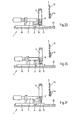
- Fig. 1 is a schematic side view of the basic structure of a device according to the invention for applying pouring elements to packs shown. 1 is the combined punching and Application unit and with 2 a downstream Called Dornrad.
- a downstream Called Dornrad In a known manner flat-folded packaging sleeves 3 in a magazine fed and the one at the end Packing jacket isolated and to a hose 4 with rectangular cross section unfolded as in Fig. 2A to C.
- the unfolded hose 4 initially for receiving a such pouring element 5 with a corresponding Punching opening.
- Stamping tool 6 which is below a Welding tool is arranged.
- Welding tool as one for the later ultrasonic welding process needed sonotrode 7 together with the Stamping tool 6 on a common slide 8 arranged. This carriage 8 can be moved linearly.
- Feeder 9 for receiving an individual Pouring element 5 and is also the anvil preferably used ultrasonic welding unit educated.
- this feed device 9 there is one corresponding to the punching tool 6 trained die 10 for performing the actual Punching process.
- the feed device 9 and the die 10 are again common, preferably in one piece arranged a carrier 11, which in turn along a rail 12, expediently the same rail for the carriage 8 is linearly movable.
- A is used to feed the individual pouring elements only schematically illustrated feed rail 13, which in a mutually working clamping element 14 ends the individual removal of pouring elements 5 by the Feed device 9 to accomplish.
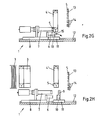
- FIG. 2G shows that the a cavity for receiving the pouring element 5 having sonotrode 7 and the trained as an anvil Feed device 9 move towards each other in order to Pouring element 5 into the punch opening of the hose 4 to move in and immediately afterwards To be able to carry out the welding process.
- the stamp of the punch 6 penetrates deeper into the Die 10 and ejects the die cut 15, as in Fig. 2G shown. Because of this "forced ejection" the removal of the die cut 15, which occurs in older Constructions often proved difficult, now on everyone Case ensured.
- the hose 4 ' is transferred with the head area ahead on a mandrel of the mandrel wheel 2 where the pack bottom is made. Doing so leaves the hose 4 'does not reach the level of its production line, so that also several according to the invention Devices can be arranged in parallel.
- a free station 2 ⁇ of the mandrel wheel 2 can be used to detect such rejects.
- a next station 3 ⁇ can discharge such Reject hoses 4 * are made as shown in dashed lines is shown. This way is reliable excluded that improperly with a Pouring element provided hoses 4 * Packing bottom formation or even the subsequent filling are fed.
- the stations 4 ⁇ and 5 ⁇ are used in a known manner Packing bottoms folded and sealed. Finally, you can the packs 4 "of the last station 6 ⁇ towards the no closer designated arrow to a subsequent (not shown) filling machine are transferred.
- the inventive method and the inventive Device provide for in a structurally simple manner reliable application of pouring elements Packing tubes, with very few moving masses are necessary in order to have a correspondingly high number of cycles to achieve packaging production.
Landscapes
- Engineering & Computer Science (AREA)
- Mechanical Engineering (AREA)
- Making Paper Articles (AREA)
- Closing Of Containers (AREA)
Abstract
- Auffalten des Packungsmantels (3) zu einem Schlauch (4), - Übergabe eines Ausgießelementes (5) an eine Zuführeinrichtung (9), - horizontales Verfahren der Zuführeinrichtung (9) unter den Schlauch (4), - Absenken des Schlauches (4) um die Zuführeinrichtung (9) herum,
- Ausstanzen einer Öffnung für das Ausgießelement (5) durch horizontales Verfahren eines ein Stanzwerkzeug (6) und ein Schweißwerkzeug aufweisenden Schlittens (8),
- Anheben des Schlauches (4), bis die Stanzöffnung sich in Höhe des von der Zuführeinrichtung (9) aufgenommenen Ausgießelementes (5) befindet, - Applizieren des Ausgießelementes (5) durch erneutes horizontales Verfahren des Schweißwerkzeuges und - Übergabe des mit Ausgießelement (5) versehenen Schlauches (4') an ein Dornrad (2).
Description
- Auffalten des Packungsmantels zu einem Schlauch,
- Übergabe eines Ausgießelementes an eine Zuführeinrichtung,
- horizontales Verfahren der Zuführeinrichtung unter den Schlauch,
- Absenken des Schlauches um die Zuführeinrichtung herum,
- Ausstanzen einer Öffnung für das Ausgießelement durch horizontales Verfahren eines ein Stanzwerkzeug und ein Schweißwerkzeug aufweisenden Schlittens,
- Anheben des Schlauches, bis die Stanzöffnung sich in Höhe des von der Zuführeinrichtung aufgenommenen Ausgießelementes befindet,
- Applizieren des Ausgießelementes durch erneutes horizontales Verfahren des Schweißwerkzeuges und
- Übergabe des mit Ausgießelement versehenen Schlauches an ein Dornrad.
- Fig. 1
- den Aufbau der erfindungsgemäßen Vorrichtung in schematischer Seitenansicht und
- Fig. 2A bis 2H
- die einzelnen beim Applizieren der Ausgießelemente ablaufenden Verfahrensschritte in kontinuierlicher Abfolge.
Claims (12)
- Verfahren zum Applizieren von Ausgießelementen an Packungen, insbesondere an quaderförmigen Mehrschichtverbundpackungen für Flüssigkeiten, wobei flachgefaltete Packungsmäntel (3) vereinzelt, ggf. vorgefaltet und zu jeweils einem rechteckigen Schlauch (4) aufgefaltet werden, wobei im Kopfbereich der späteren Packung jeweils eine Öffnung zur Aufnahme eines Ausgießelementes (5) in die aufgefalteten Schläuche (4) gestanzt und jeder Schlauch (4) mit einem Ausgießelement (5) versehen wird und wobei anschließend der Packungsboden hergestellt wird und abschließend das Füllen sowie Verschließen der fertigen Packung erfolgt,
gekennzeichnet durch die folgenden Schritte:Auffalten des Packungsmantels (3) zu einem Schlauch (4),Übergabe eines Ausgießelementes (5) an eine Zuführeinrichtung (9),horizontales Verfahren der Zuführeinrichtung (9) unter den Schlauch (4),Absenken des Schlauches (4) um die Zuführeinrichtung (9) herum,Ausstanzen einer Öffnung für das Ausgießelement (5) durch horizontales Verfahren eines ein Stanzwerkzeug (6) und ein Schweißwerkzeug aufweisenden Schlittens (8),Anheben des Schlauches (4), bis die Stanzöffnung sich in Höhe des von der Zuführeinrichtung (9) aufgenommenen Ausgießelementes (5) befindet,Applizieren des Ausgießelementes (5) durch erneutes horizontales Verfahren des Schweißwerkzeuges undÜbergabe des mit Ausgießelement (5) versehenen Schlauches (4') an ein Dornrad (2). - Verfahren nach Anspruch 1,
dadurch gekennzeichnet, dass
die flachgefalteten Packungsmäntel mit nach unten weisendem Kopfbereich zugeführt werden. - Verfahren nach Anspruch 1 oder 2,
dadurch gekennzeichnet, dass
die Ausgießelemente (5) taktweise über eine Zuführschiene (13) und ein Klemmelement (14) an die Zuführeinrichtung (9) übergeben werden. - Verfahren nach einem der Ansprüche 1 bis 3,
dadurch gekennzeichnet, dass
die mit dem Ausgießelement (5) versehenen Schläuche (4') mit ihrem Kopfbereich voran an ein Dornrad (2) zur Herstellung des Packungsbodens übergeben werden. - Verfahren nach einem der Ansprüche 1 bis 4,
dadurch gekennzeichnet, dass
als Schweißverfahren zur Applikation des Ausgießelementes (5) das Ultraschallschweißen eingesetzt wird. - Verfahren nach einem der Ansprüche 1 bis 4,
dadurch gekennzeichnet, dass
als Schweißverfahren zur Applikation des Ausgießelementes (5) das Hochfrequenzschweißen eingesetzt wird. - Vorrichtung zum Applizieren von Ausgießelementen an Packungen, insbesondere an quaderförmigen Mehrschichtverbundpackungen für Flüssigkeiten, mit einer Stanzstation zum Stanzen einer Öffnung zur Aufnahme eines Ausgießelementes (5) in einen zugeführten aufgefalteten Schlauch (4) und mit einer Station zum Applizieren der Ausgießelemente (5) in die in der Stanzstation hergestellten Öffnungen, wobei das Applizieren der Ausgießelemente (5) mittels Schweißen erfolgt, mit einer Station zum Herstellen des Packungsbodens sowie mit gegebenenfalls weiteren Stationen zum Füllen und Verschließen der fertigen Packung,
gekennzeichnet durch
eine kombinierte Stanz- und Applikationseinheit (1), bei der sowohl das Stanzwerkzeug (6) als auch das Schweißwerkzeug der Schweißeinrichtung auf einem gemeinsamen Schlitten (8) angeordnet sind und durch eine Zuführeinrichtung (9) für das Ausgießelement (5), welches auf einem Träger (11) angeordnet ist. - Vorrichtung nach Anspruch 7,
dadurch gekennzeichnet, dass
der Schlitten (8) und/oder der Träger (11) horizontal verfahrbar sind. - Vorrichtung nach Anspruch 7 oder 8,
dadurch gekennzeichnet, dass
die Zuführeinrichtung (9) für das Ausgießelement (5) gleichzeitig als Gegenwerkzeug sowohl für die Schweißeinrichtung als auch für das Stanzwerkzeug (6) ausgebildet ist. - Vorrichtung nach Anspruch 9,
dadurch gekennzeichnet, dass
die Zuführeinrichtung (9) für das Ausgießelement (5) und die Matrize (10) für das Stanzwerkzeug (6) einstückig mit dem gemeinsamen Träger (11) verbunden sind. - Vorrichtung nach einem der Ansprüche 7 bis 10,
dadurch gekennzeichnet, dass
der Schlitten (8) und der Träger (11) auf einer gemeinsamen Schiene (12) verfahrbar angeordnet sind. - Packung, insbesondere quaderförmige Mehrschichtverbundpackung mit einem einen Befestigungsflansch aufweisenden Ausgießelement (5), hergestellt nach dem Verfahren gemäß einem der Ansprüche 1 bis 6,
dadurch gekennzeichnet, dass
das Ausgießelement (5) derart an der Innenseite des Schlauches (4) appliziert ist, dass der Flansch des Ausgießelementes (5) vollflächig mit der Innenwandung des Schlauches (4) verschweißt ist.
Applications Claiming Priority (2)
| Application Number | Priority Date | Filing Date | Title |
|---|---|---|---|
| DE10313244 | 2003-03-25 | ||
| DE10313244 | 2003-03-25 |
Publications (3)
| Publication Number | Publication Date |
|---|---|
| EP1464474A2 true EP1464474A2 (de) | 2004-10-06 |
| EP1464474A3 EP1464474A3 (de) | 2008-02-06 |
| EP1464474B1 EP1464474B1 (de) | 2009-11-18 |
Family
ID=32842164
Family Applications (1)
| Application Number | Title | Priority Date | Filing Date |
|---|---|---|---|
| EP04007041A Expired - Lifetime EP1464474B1 (de) | 2003-03-25 | 2004-03-24 | Verfahren und Vorrichtung zum Applizieren von Ausgiesselementen an Packungen |
Country Status (3)
| Country | Link |
|---|---|
| EP (1) | EP1464474B1 (de) |
| DE (1) | DE502004010380D1 (de) |
| ES (1) | ES2337050T3 (de) |
Cited By (3)
| Publication number | Priority date | Publication date | Assignee | Title |
|---|---|---|---|---|
| EP3919215A1 (de) * | 2020-06-05 | 2021-12-08 | Syntegon Technology GmbH | Schweissvorrichtung sowie verfahren zum schweissen eines auslasselements an ein verpackungsmaterial |
| CN114751017A (zh) * | 2022-05-25 | 2022-07-15 | 刘堂军 | 一种精华霜软管灌装封尾机的自动上管装置及方法 |
| IT202300002988A1 (it) * | 2023-02-21 | 2024-08-21 | Galdi S R L | Gruppo di alimentazione per dispositivi di apertura in una macchina per la loro applicazione su confezioni di prodotti alimentari |
Family Cites Families (2)
| Publication number | Priority date | Publication date | Assignee | Title |
|---|---|---|---|---|
| DE7833456U1 (de) * | 1978-11-10 | 1979-11-22 | Robert Bosch Gmbh, 7000 Stuttgart | Vorrichtung zum Anbringen von Ventilen an Verpackungsbeuteln oder an einer Packstoffbahn |
| JP4788086B2 (ja) * | 2001-09-07 | 2011-10-05 | 四国化工機株式会社 | 包装機械 |
-
2004
- 2004-03-24 DE DE502004010380T patent/DE502004010380D1/de not_active Expired - Lifetime
- 2004-03-24 EP EP04007041A patent/EP1464474B1/de not_active Expired - Lifetime
- 2004-03-24 ES ES04007041T patent/ES2337050T3/es not_active Expired - Lifetime
Cited By (6)
| Publication number | Priority date | Publication date | Assignee | Title |
|---|---|---|---|---|
| EP3919215A1 (de) * | 2020-06-05 | 2021-12-08 | Syntegon Technology GmbH | Schweissvorrichtung sowie verfahren zum schweissen eines auslasselements an ein verpackungsmaterial |
| DE102020115036A1 (de) | 2020-06-05 | 2021-12-09 | Syntegon Technology Gmbh | Schweißvorrichtung sowie Verfahren zum Schweißen eines Auslasselements an ein Verpackungsmaterial |
| US11618219B2 (en) | 2020-06-05 | 2023-04-04 | Syntegon Technology Gmbh | Welding device and method for welding an outlet element to a packaging material |
| CN114751017A (zh) * | 2022-05-25 | 2022-07-15 | 刘堂军 | 一种精华霜软管灌装封尾机的自动上管装置及方法 |
| CN114751017B (zh) * | 2022-05-25 | 2024-02-06 | 上海延安药业(湖北)有限公司 | 一种精华霜软管灌装封尾机的自动上管装置及方法 |
| IT202300002988A1 (it) * | 2023-02-21 | 2024-08-21 | Galdi S R L | Gruppo di alimentazione per dispositivi di apertura in una macchina per la loro applicazione su confezioni di prodotti alimentari |
Also Published As
| Publication number | Publication date |
|---|---|
| EP1464474A3 (de) | 2008-02-06 |
| EP1464474B1 (de) | 2009-11-18 |
| DE502004010380D1 (de) | 2009-12-31 |
| ES2337050T3 (es) | 2010-04-20 |
Similar Documents
| Publication | Publication Date | Title |
|---|---|---|
| EP3439964B1 (de) | Vorrichtung und verfahren zum formen der giebelflächen von verpackungen mit schrägem giebel | |
| DE2840850C2 (de) | ||
| DE602004008696T2 (de) | Maschine zum Herstellen, Füllen und Schliessen von Netzbeuteln von einer kontinuierlichen Rolle eines Netzschlauches | |
| CH631930A5 (de) | Vorrichtung zum herstellen einer durch eine schweissnaht verschlossenen verpackung fuer garnknaeuel. | |
| EP3649052B1 (de) | Verfahren und vorrichtung zum bilden von einseitig offenen packungskoerpern mit einem oszillierenden greifer | |
| DE10355544B4 (de) | Verfahren und Vorrichtung für die Übergabe von Zuschnitten aus Umkartons an eine Weiterverarbeitungseinheit | |
| DE69932822T2 (de) | Verfahren und verpackungsmaschine zum formen von behältern | |
| EP2323935B1 (de) | Verfahren und vorrichtung zum transport von flachen werkstücken | |
| EP3019317A1 (de) | Vorrichtung und verfahren zum flüssigkeitsdichten versiegeln von zwei sich teilweise überlappenden verpackungsteilen und damit/danach hergestellter behälter | |
| DE2633341A1 (de) | Vorrichtung zur herstellung von kunststoffbeuteln mit anschlusstutzen | |
| EP0164079B1 (de) | Maschine zur Herstellung von Fliessmittelpackungen | |
| WO2023016693A1 (de) | Vorrichtung und verfahren zur herstellung gefüllter karton/kunststoff-verbundpackungen | |
| DE10114061A1 (de) | Form-, Füll- und Verschließmaschine mit Hohlraumstange | |
| EP2653420B1 (de) | Verfahren zur Bogenübergabe und Stanzmaschine mit Greifer-Transportsystem | |
| EP1464474A2 (de) | Verfahren und Vorrichtung zum Applizieren von Ausgiesselementen an Packungen und danach hergestellte Packung | |
| EP0567769B1 (de) | Vorrichtung zum Einfalten des Bodens einer Kartonpackung | |
| DE19750075C2 (de) | Verfahren zum Heraustrennen von Deckblattfolien aus einer Kunststoffolienbahn und Vorrichtung zum Durchführen des Verfahrens | |
| EP2112069B1 (de) | Verfahren und Vorrichtung zum Verpacken von portionierten Produkten in einem Einwickler | |
| EP1501734B1 (de) | Verfahren und vorrischtung zum applizieren von ausgiesselementen an packungen | |
| CH673604A5 (de) | ||
| EP0342373B1 (de) | Verfahren zum Fördern einer einseitig verschlossenen Hülse aus einer Bearbeitungsstation in eine Transporteinrichtung und Vorrichtung zur Durchführung dieses Verfahrens | |
| DE3417154C2 (de) | ||
| DE10144744B4 (de) | Verfahren zur Herstellung eines Kartonzuschnitts zur Bildung eines Behälters für Flüssigkeiten sowie Maschine zu seiner Herstellung | |
| EP1712471B1 (de) | Vorrichtung und Verfahren zur Verpackung von Artikeln | |
| EP3156340B1 (de) | Verfahren und vorrichtung zum herstellen einer verpackungseinheit |
Legal Events
| Date | Code | Title | Description |
|---|---|---|---|
| PUAI | Public reference made under article 153(3) epc to a published international application that has entered the european phase |
Free format text: ORIGINAL CODE: 0009012 |
|
| AK | Designated contracting states |
Kind code of ref document: A2 Designated state(s): AT BE BG CH CY CZ DE DK EE ES FI FR GB GR HU IE IT LI LU MC NL PL PT RO SE SI SK TR |
|
| AX | Request for extension of the european patent |
Extension state: AL LT LV MK |
|
| RIC1 | Information provided on ipc code assigned before grant |
Ipc: B31B 1/84 20060101AFI20040817BHEP Ipc: B65B 61/18 20060101ALI20071009BHEP |
|
| PUAL | Search report despatched |
Free format text: ORIGINAL CODE: 0009013 |
|
| AK | Designated contracting states |
Kind code of ref document: A3 Designated state(s): AT BE BG CH CY CZ DE DK EE ES FI FR GB GR HU IE IT LI LU MC NL PL PT RO SE SI SK TR |
|
| AX | Request for extension of the european patent |
Extension state: AL LT LV MK |
|
| 17P | Request for examination filed |
Effective date: 20080404 |
|
| AKX | Designation fees paid |
Designated state(s): DE ES FR GB |
|
| 17Q | First examination report despatched |
Effective date: 20081027 |
|
| GRAP | Despatch of communication of intention to grant a patent |
Free format text: ORIGINAL CODE: EPIDOSNIGR1 |
|
| RTI1 | Title (correction) |
Free format text: METHOD AND DEVICE FOR APPLYING DISPENSING ELEMENTS ONTO PACKAGES |
|
| GRAS | Grant fee paid |
Free format text: ORIGINAL CODE: EPIDOSNIGR3 |
|
| GRAA | (expected) grant |
Free format text: ORIGINAL CODE: 0009210 |
|
| AK | Designated contracting states |
Kind code of ref document: B1 Designated state(s): DE ES FR GB |
|
| REG | Reference to a national code |
Ref country code: GB Ref legal event code: FG4D Free format text: NOT ENGLISH |
|
| REF | Corresponds to: |
Ref document number: 502004010380 Country of ref document: DE Date of ref document: 20091231 Kind code of ref document: P |
|
| REG | Reference to a national code |
Ref country code: ES Ref legal event code: FG2A Ref document number: 2337050 Country of ref document: ES Kind code of ref document: T3 |
|
| PLBE | No opposition filed within time limit |
Free format text: ORIGINAL CODE: 0009261 |
|
| STAA | Information on the status of an ep patent application or granted ep patent |
Free format text: STATUS: NO OPPOSITION FILED WITHIN TIME LIMIT |
|
| 26N | No opposition filed |
Effective date: 20100819 |
|
| REG | Reference to a national code |
Ref country code: FR Ref legal event code: PLFP Year of fee payment: 13 |
|
| REG | Reference to a national code |
Ref country code: DE Ref legal event code: R079 Ref document number: 502004010380 Country of ref document: DE Free format text: PREVIOUS MAIN CLASS: B31B0001840000 Ipc: B31B0050840000 |
|
| REG | Reference to a national code |
Ref country code: FR Ref legal event code: PLFP Year of fee payment: 14 |
|
| REG | Reference to a national code |
Ref country code: FR Ref legal event code: PLFP Year of fee payment: 15 |
|
| PGFP | Annual fee paid to national office [announced via postgrant information from national office to epo] |
Ref country code: GB Payment date: 20190320 Year of fee payment: 16 Ref country code: FR Payment date: 20190319 Year of fee payment: 16 Ref country code: DE Payment date: 20190320 Year of fee payment: 16 |
|
| PGFP | Annual fee paid to national office [announced via postgrant information from national office to epo] |
Ref country code: ES Payment date: 20190424 Year of fee payment: 16 |
|
| REG | Reference to a national code |
Ref country code: DE Ref legal event code: R119 Ref document number: 502004010380 Country of ref document: DE |
|
| PG25 | Lapsed in a contracting state [announced via postgrant information from national office to epo] |
Ref country code: DE Free format text: LAPSE BECAUSE OF NON-PAYMENT OF DUE FEES Effective date: 20201001 Ref country code: FR Free format text: LAPSE BECAUSE OF NON-PAYMENT OF DUE FEES Effective date: 20200331 |
|
| GBPC | Gb: european patent ceased through non-payment of renewal fee |
Effective date: 20200324 |
|
| PG25 | Lapsed in a contracting state [announced via postgrant information from national office to epo] |
Ref country code: GB Free format text: LAPSE BECAUSE OF NON-PAYMENT OF DUE FEES Effective date: 20200324 |
|
| REG | Reference to a national code |
Ref country code: ES Ref legal event code: FD2A Effective date: 20210806 |
|
| PG25 | Lapsed in a contracting state [announced via postgrant information from national office to epo] |
Ref country code: ES Free format text: LAPSE BECAUSE OF NON-PAYMENT OF DUE FEES Effective date: 20200325 |