EP1464474A2 - Method and device for applying dispensing elements onto packages and packages obtained thereby - Google Patents
Method and device for applying dispensing elements onto packages and packages obtained thereby Download PDFInfo
- Publication number
- EP1464474A2 EP1464474A2 EP04007041A EP04007041A EP1464474A2 EP 1464474 A2 EP1464474 A2 EP 1464474A2 EP 04007041 A EP04007041 A EP 04007041A EP 04007041 A EP04007041 A EP 04007041A EP 1464474 A2 EP1464474 A2 EP 1464474A2
- Authority
- EP
- European Patent Office
- Prior art keywords
- pouring element
- hose
- pouring
- punching
- welding
- Prior art date
- Legal status (The legal status is an assumption and is not a legal conclusion. Google has not performed a legal analysis and makes no representation as to the accuracy of the status listed.)
- Granted
Links
Images


Classifications
-
- B—PERFORMING OPERATIONS; TRANSPORTING
- B65—CONVEYING; PACKING; STORING; HANDLING THIN OR FILAMENTARY MATERIAL
- B65B—MACHINES, APPARATUS OR DEVICES FOR, OR METHODS OF, PACKAGING ARTICLES OR MATERIALS; UNPACKING
- B65B61/00—Auxiliary devices, not otherwise provided for, for operating on sheets, blanks, webs, binding material, containers or packages
- B65B61/18—Auxiliary devices, not otherwise provided for, for operating on sheets, blanks, webs, binding material, containers or packages for making package-opening or unpacking elements
- B65B61/186—Auxiliary devices, not otherwise provided for, for operating on sheets, blanks, webs, binding material, containers or packages for making package-opening or unpacking elements by applying or incorporating rigid fittings, e.g. discharge spouts
-
- B—PERFORMING OPERATIONS; TRANSPORTING
- B29—WORKING OF PLASTICS; WORKING OF SUBSTANCES IN A PLASTIC STATE IN GENERAL
- B29C—SHAPING OR JOINING OF PLASTICS; SHAPING OF MATERIAL IN A PLASTIC STATE, NOT OTHERWISE PROVIDED FOR; AFTER-TREATMENT OF THE SHAPED PRODUCTS, e.g. REPAIRING
- B29C65/00—Joining or sealing of preformed parts, e.g. welding of plastics materials; Apparatus therefor
- B29C65/02—Joining or sealing of preformed parts, e.g. welding of plastics materials; Apparatus therefor by heating, with or without pressure
- B29C65/08—Joining or sealing of preformed parts, e.g. welding of plastics materials; Apparatus therefor by heating, with or without pressure using ultrasonic vibrations
-
- B—PERFORMING OPERATIONS; TRANSPORTING
- B29—WORKING OF PLASTICS; WORKING OF SUBSTANCES IN A PLASTIC STATE IN GENERAL
- B29C—SHAPING OR JOINING OF PLASTICS; SHAPING OF MATERIAL IN A PLASTIC STATE, NOT OTHERWISE PROVIDED FOR; AFTER-TREATMENT OF THE SHAPED PRODUCTS, e.g. REPAIRING
- B29C65/00—Joining or sealing of preformed parts, e.g. welding of plastics materials; Apparatus therefor
- B29C65/78—Means for handling the parts to be joined, e.g. for making containers or hollow articles, e.g. means for handling sheets, plates, web-like materials, tubular articles, hollow articles or elements to be joined therewith; Means for discharging the joined articles from the joining apparatus
- B29C65/7802—Positioning the parts to be joined, e.g. aligning, indexing or centring
- B29C65/7838—Positioning the parts to be joined, e.g. aligning, indexing or centring from the inside, e.g. of tubular or hollow articles
-
- B—PERFORMING OPERATIONS; TRANSPORTING
- B29—WORKING OF PLASTICS; WORKING OF SUBSTANCES IN A PLASTIC STATE IN GENERAL
- B29C—SHAPING OR JOINING OF PLASTICS; SHAPING OF MATERIAL IN A PLASTIC STATE, NOT OTHERWISE PROVIDED FOR; AFTER-TREATMENT OF THE SHAPED PRODUCTS, e.g. REPAIRING
- B29C65/00—Joining or sealing of preformed parts, e.g. welding of plastics materials; Apparatus therefor
- B29C65/78—Means for handling the parts to be joined, e.g. for making containers or hollow articles, e.g. means for handling sheets, plates, web-like materials, tubular articles, hollow articles or elements to be joined therewith; Means for discharging the joined articles from the joining apparatus
- B29C65/7841—Holding or clamping means for handling purposes
-
- B—PERFORMING OPERATIONS; TRANSPORTING
- B29—WORKING OF PLASTICS; WORKING OF SUBSTANCES IN A PLASTIC STATE IN GENERAL
- B29C—SHAPING OR JOINING OF PLASTICS; SHAPING OF MATERIAL IN A PLASTIC STATE, NOT OTHERWISE PROVIDED FOR; AFTER-TREATMENT OF THE SHAPED PRODUCTS, e.g. REPAIRING
- B29C66/00—General aspects of processes or apparatus for joining preformed parts
- B29C66/50—General aspects of joining tubular articles; General aspects of joining long products, i.e. bars or profiled elements; General aspects of joining single elements to tubular articles, hollow articles or bars; General aspects of joining several hollow-preforms to form hollow or tubular articles
- B29C66/51—Joining tubular articles, profiled elements or bars; Joining single elements to tubular articles, hollow articles or bars; Joining several hollow-preforms to form hollow or tubular articles
- B29C66/53—Joining single elements to tubular articles, hollow articles or bars
- B29C66/532—Joining single elements to the wall of tubular articles, hollow articles or bars
- B29C66/5324—Joining single elements to the wall of tubular articles, hollow articles or bars said single elements being substantially annular, i.e. of finite length
- B29C66/53245—Joining single elements to the wall of tubular articles, hollow articles or bars said single elements being substantially annular, i.e. of finite length said articles being hollow
- B29C66/53246—Joining single elements to the wall of tubular articles, hollow articles or bars said single elements being substantially annular, i.e. of finite length said articles being hollow said single elements being spouts, e.g. joining spouts to containers
-
- B—PERFORMING OPERATIONS; TRANSPORTING
- B29—WORKING OF PLASTICS; WORKING OF SUBSTANCES IN A PLASTIC STATE IN GENERAL
- B29C—SHAPING OR JOINING OF PLASTICS; SHAPING OF MATERIAL IN A PLASTIC STATE, NOT OTHERWISE PROVIDED FOR; AFTER-TREATMENT OF THE SHAPED PRODUCTS, e.g. REPAIRING
- B29C66/00—General aspects of processes or apparatus for joining preformed parts
- B29C66/50—General aspects of joining tubular articles; General aspects of joining long products, i.e. bars or profiled elements; General aspects of joining single elements to tubular articles, hollow articles or bars; General aspects of joining several hollow-preforms to form hollow or tubular articles
- B29C66/61—Joining from or joining on the inside
-
- B—PERFORMING OPERATIONS; TRANSPORTING
- B29—WORKING OF PLASTICS; WORKING OF SUBSTANCES IN A PLASTIC STATE IN GENERAL
- B29C—SHAPING OR JOINING OF PLASTICS; SHAPING OF MATERIAL IN A PLASTIC STATE, NOT OTHERWISE PROVIDED FOR; AFTER-TREATMENT OF THE SHAPED PRODUCTS, e.g. REPAIRING
- B29C66/00—General aspects of processes or apparatus for joining preformed parts
- B29C66/50—General aspects of joining tubular articles; General aspects of joining long products, i.e. bars or profiled elements; General aspects of joining single elements to tubular articles, hollow articles or bars; General aspects of joining several hollow-preforms to form hollow or tubular articles
- B29C66/63—Internally supporting the article during joining
-
- B—PERFORMING OPERATIONS; TRANSPORTING
- B29—WORKING OF PLASTICS; WORKING OF SUBSTANCES IN A PLASTIC STATE IN GENERAL
- B29C—SHAPING OR JOINING OF PLASTICS; SHAPING OF MATERIAL IN A PLASTIC STATE, NOT OTHERWISE PROVIDED FOR; AFTER-TREATMENT OF THE SHAPED PRODUCTS, e.g. REPAIRING
- B29C66/00—General aspects of processes or apparatus for joining preformed parts
- B29C66/80—General aspects of machine operations or constructions and parts thereof
- B29C66/81—General aspects of the pressing elements, i.e. the elements applying pressure on the parts to be joined in the area to be joined, e.g. the welding jaws or clamps
- B29C66/814—General aspects of the pressing elements, i.e. the elements applying pressure on the parts to be joined in the area to be joined, e.g. the welding jaws or clamps characterised by the design of the pressing elements, e.g. of the welding jaws or clamps
- B29C66/8141—General aspects of the pressing elements, i.e. the elements applying pressure on the parts to be joined in the area to be joined, e.g. the welding jaws or clamps characterised by the design of the pressing elements, e.g. of the welding jaws or clamps characterised by the surface geometry of the part of the pressing elements, e.g. welding jaws or clamps, coming into contact with the parts to be joined
- B29C66/81431—General aspects of the pressing elements, i.e. the elements applying pressure on the parts to be joined in the area to be joined, e.g. the welding jaws or clamps characterised by the design of the pressing elements, e.g. of the welding jaws or clamps characterised by the surface geometry of the part of the pressing elements, e.g. welding jaws or clamps, coming into contact with the parts to be joined comprising a single cavity, e.g. a groove
-
- B—PERFORMING OPERATIONS; TRANSPORTING
- B29—WORKING OF PLASTICS; WORKING OF SUBSTANCES IN A PLASTIC STATE IN GENERAL
- B29L—INDEXING SCHEME ASSOCIATED WITH SUBCLASS B29C, RELATING TO PARTICULAR ARTICLES
- B29L2031/00—Other particular articles
- B29L2031/712—Containers; Packaging elements or accessories, Packages
- B29L2031/7162—Boxes, cartons, cases
- B29L2031/7166—Cartons of the fruit juice or milk type, i.e. containers of polygonal cross sections formed by folding blanks into a tubular body with end-closing or contents-supporting elements, e.g. gable type containers
-
- B—PERFORMING OPERATIONS; TRANSPORTING
- B31—MAKING ARTICLES OF PAPER, CARDBOARD OR MATERIAL WORKED IN A MANNER ANALOGOUS TO PAPER; WORKING PAPER, CARDBOARD OR MATERIAL WORKED IN A MANNER ANALOGOUS TO PAPER
- B31B—MAKING CONTAINERS OF PAPER, CARDBOARD OR MATERIAL WORKED IN A MANNER ANALOGOUS TO PAPER
- B31B50/00—Making rigid or semi-rigid containers, e.g. boxes or cartons
- B31B50/74—Auxiliary operations
- B31B50/81—Forming or attaching accessories, e.g. opening devices, closures or tear strings
- B31B50/84—Forming or attaching means for filling or dispensing contents, e.g. valves or spouts
Definitions
- the invention relates to a method and a device for applying pouring elements to packs, especially cuboid Multi-layer composite packs for liquids, whereby flat folded packing sleeves, if necessary pre-folded and each into a rectangular tube be unfolded, with the head area of the later Pack an opening for receiving one Pouring element punched into the unfolded hoses and each hose is provided with a pouring element and the package bottom is then produced and finally filling and closing the finished package and a so produced Pack.
- Beverage packs are in multiple copies known, for example as flat gable composite packages. You will find primarily in the field of Liquid packaging in connection with cold, cold sterile, Hot and aseptic filling use.
- Such packs are often used today reclosable pouring elements provided to on the one hand the first opening of the package without Tools to facilitate and on the other hand for secure reclosing so that the product in the package Quality properties such as taste, vitamins etc. to for final emptying.
- packs which are associated with Pouring elements are provided, which through an opening brought in the head area of the multilayer composite and there, usually with one with the inner wall connecting flange, are attached (EP-A2-1 291 162). It is precisely with the aforementioned packs problematic, the application of the pouring element first to carry out after filling the pack, as here hygienic impairments of the product and / or the Pack or the pourer to be introduced due to inadequate welding of the flange to the Product wet multi-layer composite material are to be feared.
- the invention is therefore based on the object known and previously described methods or associated device so design and to further develop that with less constructive effort the application of pouring elements is simplified.
- a space-saving solution is desired that several production lines also work well side by side order.
- the task is solved by a combined punching and application unit in which both the punching tool and the welding tool of the Welding device on a common carriage are arranged and by a feed device for the Pouring element, which is arranged on a carrier.
- the invention has recognized that it is possible to both processes of punching and applying the Perform pouring element in a single station can, whereby - due to the small construction - a modular arrangement of several devices possible to arrange several parallel production lines is. In this way, the known structure of a "Longitudinal runner" are maintained.
- each hose is directed towards its longitudinal axis first into the punching position and then moved to the application position.
- the moving masses are compared with the generic device significantly reduced.
- the flat-folded hoses with downward pointing Head area fed has the advantage that the Application of the pouring element in the lower area of the Hose can take place, and that to that necessary aggregates not from the presence of the Hose are hindered.
- Another embodiment of the invention provides that the pouring elements are cycled over a Feed rail and a clamping element to the Feeding device are handed over. This makes it easier particularly favorable supply of pouring elements.
- Another teaching of the invention provides that with the pouring element provided hoses with their Head area ahead of a mandrel wheel to produce the Packing bottom are handed over. By this measure can be an immediate handover to a downstream Station take place without, as with the generic State of the art provided with the pouring element Hoses have to be turned again by 180 °.
- the carriage of the punch and / or the carrier for the feeder of the Welding device can be moved horizontally.
- Feeding device for the pouring element at the same time as Counter tool for both the welding device and is designed for the punching tool. Especially It is useful if the feed device for the Pouring element and the die for the punching tool are integrally connected to the common carrier. This ensures that the path of the Hose from the punching position to the Application position can be kept extremely small.
- a manufactured according to the inventive method Pack is characterized in that the Pouring element in this way on the inside of the hose is applied that the flange of the pouring element in fully welded to the inner wall of the hose is. In this way it is ensured that the open edge of the composite material in the area of Punch opening through the fully welded Flange of the pouring element is not the same as that in the package product in contact. A elaborate treatment of this open edge can omitted.
- the pack so produced also has the Advantage that any abrasion that occurs during punching of the composite material by the immediately following Do not insert and weld the pouring element in the pack can get. This in turn has one less cleaning effort.
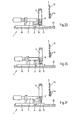
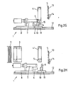
- Fig. 1 is a schematic side view of the basic structure of a device according to the invention for applying pouring elements to packs shown. 1 is the combined punching and Application unit and with 2 a downstream Called Dornrad.
- a downstream Called Dornrad In a known manner flat-folded packaging sleeves 3 in a magazine fed and the one at the end Packing jacket isolated and to a hose 4 with rectangular cross section unfolded as in Fig. 2A to C.
- the unfolded hose 4 initially for receiving a such pouring element 5 with a corresponding Punching opening.
- Stamping tool 6 which is below a Welding tool is arranged.
- Welding tool as one for the later ultrasonic welding process needed sonotrode 7 together with the Stamping tool 6 on a common slide 8 arranged. This carriage 8 can be moved linearly.
- Feeder 9 for receiving an individual Pouring element 5 and is also the anvil preferably used ultrasonic welding unit educated.
- this feed device 9 there is one corresponding to the punching tool 6 trained die 10 for performing the actual Punching process.
- the feed device 9 and the die 10 are again common, preferably in one piece arranged a carrier 11, which in turn along a rail 12, expediently the same rail for the carriage 8 is linearly movable.
- A is used to feed the individual pouring elements only schematically illustrated feed rail 13, which in a mutually working clamping element 14 ends the individual removal of pouring elements 5 by the Feed device 9 to accomplish.
- FIG. 2G shows that the a cavity for receiving the pouring element 5 having sonotrode 7 and the trained as an anvil Feed device 9 move towards each other in order to Pouring element 5 into the punch opening of the hose 4 to move in and immediately afterwards To be able to carry out the welding process.
- the stamp of the punch 6 penetrates deeper into the Die 10 and ejects the die cut 15, as in Fig. 2G shown. Because of this "forced ejection" the removal of the die cut 15, which occurs in older Constructions often proved difficult, now on everyone Case ensured.
- the hose 4 ' is transferred with the head area ahead on a mandrel of the mandrel wheel 2 where the pack bottom is made. Doing so leaves the hose 4 'does not reach the level of its production line, so that also several according to the invention Devices can be arranged in parallel.
- a free station 2 ⁇ of the mandrel wheel 2 can be used to detect such rejects.
- a next station 3 ⁇ can discharge such Reject hoses 4 * are made as shown in dashed lines is shown. This way is reliable excluded that improperly with a Pouring element provided hoses 4 * Packing bottom formation or even the subsequent filling are fed.
- the stations 4 ⁇ and 5 ⁇ are used in a known manner Packing bottoms folded and sealed. Finally, you can the packs 4 "of the last station 6 ⁇ towards the no closer designated arrow to a subsequent (not shown) filling machine are transferred.
- the inventive method and the inventive Device provide for in a structurally simple manner reliable application of pouring elements Packing tubes, with very few moving masses are necessary in order to have a correspondingly high number of cycles to achieve packaging production.
Landscapes
- Engineering & Computer Science (AREA)
- Mechanical Engineering (AREA)
- Making Paper Articles (AREA)
- Closing Of Containers (AREA)
Abstract
Description
Die Erfindung betrifft ein Verfahren und eine Vorrichtung zum Applizieren von Ausgießelementen an Packungen, insbesondere an quaderförmigen Mehrschichtverbundpackungen für Flüssigkeiten, wobei flachgefaltete Packungsmäntel vereinzelt, ggf. vorgefaltet und zu jeweils einem rechteckigen Schlauch aufgefaltet werden, wobei im Kopfbereich der späteren Packung jeweils eine Öffnung zur Aufnahme eines Ausgießelementes in die aufgefalteten Schläuche gestanzt und jeder Schlauch mit einem Ausgießelement versehen wird und wobei anschließend der Packungsboden hergestellt wird und abschließend das Füllen sowie Verschließen der fertigen Packung erfolgt sowie eine so hergestellte Packung.The invention relates to a method and a device for applying pouring elements to packs, especially cuboid Multi-layer composite packs for liquids, whereby flat folded packing sleeves, if necessary pre-folded and each into a rectangular tube be unfolded, with the head area of the later Pack an opening for receiving one Pouring element punched into the unfolded hoses and each hose is provided with a pouring element and the package bottom is then produced and finally filling and closing the finished package and a so produced Pack.
Als Mehrschichtverbundpackungen ausgebildete Getränkepackungen sind in vielfacher Ausfertigung bekannt, beispielsweise als Flachgiebelverbundpackungen. Sie finden vornehmlich auf dem Gebiet der Flüssigkeitsverpackung im Zusammenhang mit Kalt-, Kalt-Steril-, Heiß- und aseptischer Füllung Verwendung.Trained as multi-layer composite packs Beverage packs are in multiple copies known, for example as flat gable composite packages. You will find primarily in the field of Liquid packaging in connection with cold, cold sterile, Hot and aseptic filling use.
Solche Packungen werden heute häufig mit wiederverschließbaren Ausgießelementen versehen, um einerseits die erstmalige Öffnung der Packung ohne Zuhilfenahme von Werkzeugen zu erleichtern und andererseits zum sicheren Wiederverschließen, damit das in der Packung befindliche Produkt seine Qualitätseigenschaften wie Geschmack, Vitamine etc. bis zum endgültigen Leeren behält.Such packs are often used today reclosable pouring elements provided to on the one hand the first opening of the package without Tools to facilitate and on the other hand for secure reclosing so that the product in the package Quality properties such as taste, vitamins etc. to for final emptying.
Insbesondere sind Packungen bekannt, die mit Ausgießelementen versehen sind, welche durch eine Öffnung im Kopfbereich der Mehrschichtverbundpackung gebracht wird und dort, meist mit einem mit der Innenwandung zu verbindenden Flansch, befestigt werden (EP-A2-1 291 162). Gerade bei den vorgenannten Packungen ist es problematisch, die Applikation des Ausgießelementes erst nach der Füllung der Packung durchzuführen, da hier hygienische Beeinträchtigungen des Produktes und/oder der Packung bzw. des einzubringenden Ausgießers aufgrund unzureichender Verschweißung des Flansches mit vom Produkt benetzten Mehrschichtverbundmaterial zu befürchten sind.In particular, packs are known which are associated with Pouring elements are provided, which through an opening brought in the head area of the multilayer composite and there, usually with one with the inner wall connecting flange, are attached (EP-A2-1 291 162). It is precisely with the aforementioned packs problematic, the application of the pouring element first to carry out after filling the pack, as here hygienic impairments of the product and / or the Pack or the pourer to be introduced due to inadequate welding of the flange to the Product wet multi-layer composite material are to be feared.
Aus der DE 102 20 058 A1 sind ferner ein Verfahren und eine Vorrichtung zum Applizieren von Ausgießelementen an Packungen bekannt, in denen flachgefaltete Packungsmäntel vereinzelt und zu einem rechteckigen Schlauch aufgefaltet werden. Dieser Schlauch wird dann zunächst in eine Stanzstation transportiert, in der eine Öffnung zur Aufnahme des Ausgießelementes in den Schlauch gestanzt wird. Anschließend erfolgt der Transport des Schlauches in eine Station zum Applizieren von Ausgießelementen in die zuvor hergestellten Öffnungen. Von dort wird der mit dem Ausgießelement versehene Schlauch an nachgeordnete Stationen zum Herstellen des Packungsbodens und Füllen sowie Verschließen der fertigen Packung weitergegeben. Diese bekannte Konstruktion sieht eine drehbare Transporteinrichtung vor, auf der jeweils eine Mehrzahl von Packungen zunächst der Stanzstation und anschließend der Applikationsstation bzw. noch weiteren Stationen zugeführt werden. Der Nachteil an dieser konstruktiven Ausgestaltung ist darin zu sehen, dass eine solche Vorrichtung relativ groß baut und dass es daher nur mit sehr hohem Aufwand möglich ist, mehrere parallel angeordnete Fertigungslinien vorzusehen.DE 102 20 058 A1 also describes a method and a device for applying pouring elements Known packs in which flat-folded packing sleeves isolated and folded into a rectangular tube become. This hose is then first in a Punching station transported in an opening to the The pouring element is punched into the hose becomes. The hose is then transported in a station for applying pouring elements in the openings previously made. From there, the with the pouring element provided hose to downstream Stations for making the pack bottom and filling as well as closing the finished package. This known construction sees a rotatable one Transport device in front, on each of which a plurality of packs first the punching station and then the application station or other stations are fed. The disadvantage of this constructive Design can be seen in the fact that such Device builds relatively large and that it is therefore only with very high effort is possible, several in parallel to provide arranged production lines.
Die Erfindung liegt daher die Aufgabe zugrunde, das bekannte und zuvor näher beschriebene Verfahren bzw. die zugehörige Vorrichtung so auszugestalten und weiterzubilden, dass bei konstruktiv geringerem Aufwand die Applikation von Ausgießelementen vereinfacht wird. Darüber hinaus ist eine raumsparende Lösung erwünscht, so dass sich mehrere Fertigungslinien auch gut nebeneinander anordnen lassen.The invention is therefore based on the object known and previously described methods or associated device so design and to further develop that with less constructive effort the application of pouring elements is simplified. In addition, a space-saving solution is desired that several production lines also work well side by side order.
Diese Aufgabe wird bei einem Verfahren gemäß dem Oberbegriff von Anspruch 1 durch die folgenden Schritte gelöst:
- Auffalten des Packungsmantels zu einem Schlauch,
- Übergabe eines Ausgießelementes an eine Zuführeinrichtung,
- horizontales Verfahren der Zuführeinrichtung unter den Schlauch,
- Absenken des Schlauches um die Zuführeinrichtung herum,
- Ausstanzen einer Öffnung für das Ausgießelement durch horizontales Verfahren eines ein Stanzwerkzeug und ein Schweißwerkzeug aufweisenden Schlittens,
- Anheben des Schlauches, bis die Stanzöffnung sich in Höhe des von der Zuführeinrichtung aufgenommenen Ausgießelementes befindet,
- Applizieren des Ausgießelementes durch erneutes horizontales Verfahren des Schweißwerkzeuges und
- Übergabe des mit Ausgießelement versehenen Schlauches an ein Dornrad.
- Unfold the packing jacket into a tube,
- Transfer of a pouring element to a feed device,
- horizontal movement of the feed device under the hose,
- Lowering the hose around the feed device,
- Punching out an opening for the pouring element by horizontally moving a slide having a punching tool and a welding tool,
- Lifting the hose until the punching opening is at the level of the pouring element received by the feed device,
- Applying the pouring element by renewed horizontal movement of the welding tool and
- Transfer of the hose with pouring element to a mandrel wheel.
Vorrichtungsmäßig erfolgt die Lösung der Aufgabe durch eine kombinierte Stanz- und Applikationseinheit, bei der sowohl das Stanzwerkzeug als auch das Schweißwerkzeug der Schweißeinrichtung auf einem gemeinsamen Schlitten angeordnet sind und durch eine Zuführeinrichtung für das Ausgießelement, welches auf einem Träger angeordnet ist.In terms of the device, the task is solved by a combined punching and application unit in which both the punching tool and the welding tool of the Welding device on a common carriage are arranged and by a feed device for the Pouring element, which is arranged on a carrier.
Die Erfindung hat erkannt, dass es möglich ist, die beiden Vorgänge des Stanzens und Applizierens des Ausgießelementes in einer einzigen Station durchführen zu können, wobei - aufgrund der klein bauenden Ausführung - ein modulartiges Aneinanderreihen mehrerer Vorrichtungen zum Anordnen mehrerer paralleler Fertigungslinien möglich ist. Auf diese Weise kann der bekannte Aufbau eines "Längsläufers" beibehalten werden.The invention has recognized that it is possible to both processes of punching and applying the Perform pouring element in a single station can, whereby - due to the small construction - a modular arrangement of several devices possible to arrange several parallel production lines is. In this way, the known structure of a "Longitudinal runner" are maintained.
Gemäß der Erfindung wird jeder Schlauch in Richtung seiner Längsachse zunächst in die Stanzposition und anschließend in die Applikationsposition bewegt. Auf diese Weise werden die bewegten Massen verglichen mit der gattungsgemäßen Vorrichtung deutlich reduziert.According to the invention, each hose is directed towards its longitudinal axis first into the punching position and then moved to the application position. On in this way the moving masses are compared with the generic device significantly reduced.
Nach einer weiteren Ausgestaltung der Erfindung werden die flachgefalteten Schläuche mit nach unten weisendem Kopfbereich zugeführt. Diese hat den Vorteil, dass die Applikation des Ausgießelementes im unteren Bereich des Schlauches stattfinden kann, und dass die dazu notwendigen Aggregate nicht von der Anwesenheit des Schlauches behindert werden. According to a further embodiment of the invention the flat-folded hoses with downward pointing Head area fed. This has the advantage that the Application of the pouring element in the lower area of the Hose can take place, and that to that necessary aggregates not from the presence of the Hose are hindered.
Eine andere erfindungsgemäße Ausgestaltung der Erfindung sieht vor, dass die Ausgießelemente taktweise über eine Zuführschiene und ein Klemmelement an die Zuführeinrichtung übergeben werden. Dies erleichtert eine besonders günstige Zuführung von Ausgießelementen.Another embodiment of the invention provides that the pouring elements are cycled over a Feed rail and a clamping element to the Feeding device are handed over. This makes it easier particularly favorable supply of pouring elements.
Eine weitere Lehre der Erfindung sieht vor, dass die mit dem Ausgießelement versehenen Schläuche mit ihrem Kopfbereich voran an ein Dornrad zur Herstellung des Packungsbodens übergeben werden. Durch diese Maßnahme kann eine unmittelbare Übergabe an eine nachgeschaltete Station erfolgen, ohne dass, wie beim gattungsbildenden Stand der Technik, die mit dem Ausgießelement versehenen Schläuche noch einmal um 180° gedreht werden müssen.Another teaching of the invention provides that with the pouring element provided hoses with their Head area ahead of a mandrel wheel to produce the Packing bottom are handed over. By this measure can be an immediate handover to a downstream Station take place without, as with the generic State of the art provided with the pouring element Hoses have to be turned again by 180 °.
Bevorzugt werden als Schweißverfahren entweder das Ultraschallschweißen oder das Hochfrequenzschweißen eingesetzt.Either that is preferred as the welding process Ultrasonic welding or high-frequency welding used.
Gemäß einer weiteren zweckmäßigen Ausgestaltung der Erfindung ist der Schlitten des Stanzwerkzeuges und/oder der Träger für die Zuführeinrichtung der Schweißeinrichtung horizontal verfahrbar. Durch diese konstruktive Maßnahme ist sichergestellt, dass ein einziger Antrieb für den Stanzbetrieb und für das anschließende Verschweißen des Ausgießelementes ausreichend ist, wobei für jeden zugeführten Schlauch ein zweimaliger Hub dieser Einheit notwendig ist.According to a further expedient embodiment of the Invention is the carriage of the punch and / or the carrier for the feeder of the Welding device can be moved horizontally. Through this constructive measure ensures that a only drive for punching and for that subsequent welding of the pouring element is sufficient, with one for each hose supplied double stroke of this unit is necessary.
Eine weitere Lehre der Erfindung sieht vor, dass die Zuführeinrichtung für das Ausgießelement gleichzeitig als Gegenwerkzeug sowohl für die Schweißeinrichtung als auch für das Stanzwerkzeug ausgebildet ist. Besonders zweckmäßig ist es, wenn die Zuführeinrichtung für das Ausgießelement und die Matrize für das Stanzwerkzeug einstückig mit dem gemeinsamen Träger verbunden sind. Dadurch wird erreicht, dass der zurückzulegende Weg des Schlauches von der Stanzposition in die Applikationsposition äußerst klein gehalten werden kann.Another teaching of the invention provides that the Feeding device for the pouring element at the same time as Counter tool for both the welding device and is designed for the punching tool. Especially It is useful if the feed device for the Pouring element and the die for the punching tool are integrally connected to the common carrier. This ensures that the path of the Hose from the punching position to the Application position can be kept extremely small.
Nach einer weiteren Ausgestaltung der Erfindung sind der Schlitten und der Träger auf einer gemeinsamen Schiene verfahrbar angeordnet. Auf diese Weise ist mit geringem konstruktiven Aufwand sichergestellt, dass der zu bearbeitende Packungsschlauch nur in seiner Längsrichtung bewegt werden muss. Das Durchstecken des Ausgießelementes vor dem Schweißvorgang erfolgt durch eine lineare Bewegung des Trägers quer zur Längsrichtung des Schlauches.According to a further embodiment of the invention Sledge and the carrier on a common rail movably arranged. This way is with little constructive effort ensures that the too processing packaging tube only in its longitudinal direction must be moved. Pushing through the pouring element before welding is done by a linear Movement of the carrier transverse to the longitudinal direction of the Hose.
Durch den Wegfall der drehbaren Transporteinrichtung gemäß der gattungsgemäßen Vorrichtung entfällt auch die Möglichkeit, innerhalb dieser Vorrichtung eine Station zum Ausschleusen nicht oder nicht ordnungsgemäß mit einem Ausgießelement versehener Schläuche vorzusehen. Eine solche Möglichkeit ist jedoch für die erfindungsgemäße Vorrichtung wesentlich, da eine Fehlfunktion beim Applizieren von Ausgießelementen niemals vollständig ausgeschlossen werden kann.By eliminating the rotatable transport device according to the generic device, the Possibility of a station within this device to discharge or not properly with a Pouring element provided hoses. A however, such possibility is for the invention Device essential because of a malfunction in the Never apply pouring elements completely can be excluded.
Um nun zu vermeiden, dass eine solche Fehlfunktion erst im späteren Verlauf beim oder gar nach dem Füllen detektiert wird, ist vorgesehen, dass eine Station des Dornrades zum Ausschleusen nicht oder nicht ordnungsgemäß mit einem Ausgießelement versehener Schläuche vorgesehen ist. Da die für die in Rede stehenden Packungen verwendeten Dornräder stets wenigstens sechs Dorne aufweisen, ist das Vorsehen einer solchen frühzeitigen Möglichkeit der Ausschleusung konstruktiv ohne weiteres realisierbar.In order to avoid such a malfunction first later during or after filling is detected, it is provided that a station of the Mandrel wheel to discharge not or not properly provided with a pouring element hoses is. As for the packs in question always used at least six mandrels is the provision of such an early Possibility of discharging constructively without further notice realizable.
Eine nach dem erfindungsgemäßen Verfahren gefertigte Packung zeichnet sich dadurch aus, dass das Ausgießelement derart an der Innenseite des Schlauches appliziert ist, dass der Flansch des Ausgießelementes im vollfähig mit der Innenwandung des Schlauches verschweißt ist. Auf diese Weise ist es sichergestellt, dass die offene Kante des Verbundmaterials im Bereich der Stanzöffnung durch den vollflächig aufgeschweißten Flansch des Ausgießelementes nicht mit dem in der Packung befindlichen Produkt in Kontakt treten kann. Eine aufwendige Behandlung dieser offenen Kante kann also entfallen.A manufactured according to the inventive method Pack is characterized in that the Pouring element in this way on the inside of the hose is applied that the flange of the pouring element in fully welded to the inner wall of the hose is. In this way it is ensured that the open edge of the composite material in the area of Punch opening through the fully welded Flange of the pouring element is not the same as that in the package product in contact. A elaborate treatment of this open edge can omitted.
Die so hergestellte Packung hat darüber hinaus den Vorteil, dass etwaiger beim Stanzen entstehender Abrieb des Verbundmaterials durch das unmittelbar anschließende Einsetzen und Verschweißen des Ausgießelementes nicht in die Packung gelangen kann. Dies wiederum hat einen geringeren Reinigungsaufwand zur Folge.The pack so produced also has the Advantage that any abrasion that occurs during punching of the composite material by the immediately following Do not insert and weld the pouring element in the pack can get. This in turn has one less cleaning effort.
Die Erfindung wird nachfolgend anhand einer lediglich ein bevorzugtes Ausführungsbeispiel darstellenden Zeichnung näher erläutert. In der Zeichnung zeigen:
- Fig. 1
- den Aufbau der erfindungsgemäßen Vorrichtung in schematischer Seitenansicht und
- Fig. 2A bis 2H
- die einzelnen beim Applizieren der Ausgießelemente ablaufenden Verfahrensschritte in kontinuierlicher Abfolge.
- Fig. 1
- the structure of the device according to the invention in a schematic side view and
- 2A to 2H
- the individual process steps taking place when the pouring elements are applied in a continuous sequence.
In Fig. 1 ist in schematischer Seitenansicht der
grundsätzliche Aufbau einer erfindungsgemäßen Vorrichtung
zum Applizieren von Ausgießelementen an Packungen
dargestellt. Dabei ist mit 1 die kombinierte Stanz- und
Applikationseinheit und mit 2 ein nachgeschaltetes
Dornrad bezeichnet. In bekannter Weise werden
flachgefaltete Packungsmäntel 3 in einem Magazin
zugeführt und jeweils der am Ende befindliche
Packungsmantel vereinzelt und zu einem Schlauch 4 mit
rechteckigem Querschnitt aufgefaltet wie in den Fig. 2A
bis C dargestellt.In Fig. 1 is a schematic side view of the
basic structure of a device according to the invention
for applying pouring elements to packs
shown. 1 is the combined punching and
Application unit and with 2 a downstream
Called Dornrad. In a known manner
flat-folded
Bevor nun die Applikation von gleichfalls stetig
zugeführten Ausgießelementen 5 erfolgen kann, muss der
aufgefaltete Schlauch 4 zunächst zur Aufnahme eines
solchen Ausgießelementes 5 mit einer entsprechenden
Stanzöffnung versehen werden. Dazu dient im dargestellten
und insoweit bevorzugten Ausführungsbeispiel ein
Stanzwerkzeug 6, welches unterhalb eines
Schweißwerkzeuges angeordnet ist. Im dargestellten und
insoweit bevorzugten Ausführungsbeispiel ist das
Schweißwerkzeug als eine für den späteren Ultraschall-Schweißvorgang
benötigte Sonotrode 7 gemeinsam mit dem
Stanzwerkzeug 6 auf einem gemeinsamen Schlitten 8
angeordnet. Dieser Schlitten 8 ist linear verfahrbar. Before the application of also steadily
supplied pouring
Wie weiter unten im einzelnen ausgeführt, dient eine
Zuführeinrichtung 9 zur Aufnahme eines einzelnen
Ausgießelementes 5 und ist gleichzeitig als Amboss der
bevorzugt verwendeten Ultraschall-Schweißeinheit
ausgebildet. Unterhalb dieser Zuführeinrichtung 9
befindet sich eine entsprechend dem Stanzwerkzeug 6
ausgebildete Matrize 10 zur Durchführung des eigentlichen
Stanzvorganges. Die Zuführeinrichtung 9 und die Matrize
10 sind wiederum gemeinsam, bevorzugt einstückig, auf
einem Träger 11 angeordnet, welcher wiederum entlang
einer Schiene 12, zweckmäßigerweise derselben Schiene für
den Schlitten 8, linear verfahrbar ist.As detailed below, one serves
Zur Zuführung der einzelnen Ausgießelemente dient eine
nur schematisch dargestellte Zuführschiene 13, die in
einem wechselseitig arbeitenden Klemmelement 14 endet, um
die einzelne Entnahme von Ausgießelementen 5 durch die
Zuführeinrichtung 9 zu bewerkstelligen.A is used to feed the individual pouring elements
only schematically illustrated
Die eigentliche Verfahrensabfolge ist nachfolgend in den
Fig. 2A bis 2H näher beschrieben. In Fig. 2A wird der
vereinzelte Packungsmantel 3 aufgefaltet, gleichzeitig
fährt der Träger 11 nach rechts in eine Stellung
unterhalb der Zuführschiene 13, wie in Fig. 2B
dargestellt. Dort erfolgt mittels des Klemmelementes 14
eine Übergabe eines Ausgießelementes 5 an die
Zuführeinrichtung 9. In Fig. 2C fährt der Träger 11 mit
dem Ausgießelement 5 unter den nun vollständig
aufgefalteten Schlauch 4. In dieser Stellung senkt sich
der aufgefaltete Schlauch 4 so weit ab, bis die auf dem
Träger 11 befindliche Matrize sich im Inneren des
Schlauches befindet, wie in Fig. 2D dargestellt.
Anschließend wird durch lineare Bewegung des Schlittens 8
auf der Schiene 12 in Richtung des Schlauches 4 der
Stanzvorgang durchgeführt, indem das Stanzwerkzeug 6 sich
in die Matrize 10 hinein- und hinausbewegt.The actual process sequence is shown in the following
2A to 2H described in more detail. 2A, the
Nach dem Entfernen des Stanzwerkzeuges 6 aus der Matrize
10 wird der Schlauch 4 so weit angehoben, bis sich die
Stanzöffnung in Höhe des von der Zuführeinheit 9
aufgenommenen Ausgießelementes 5 befindet, wie in Fig. 2F
dargestellt. In Fig. 2G ist nun dargestellt, dass die
einen Hohlraum zur Aufnahme des Ausgießelementes 5
aufweisende Sonotrode 7 und die als Amboss ausgebildete
Zuführeinrichtung 9 aufeinander zufahren, um das
Ausgießelement 5 in die Stanzöffnung des Schlauches 4
hineinzubewegen und unmittelbar anschließend den
Schweißvorgang durchführen zu können. Durch das Verfahren
des Ambosses in Richtung der Sonotrode 7 und dem
anschließenden Hub von Sonotrode 7 und Stanzwerkzeug 6
dringt der Stempel des Stanzwerkzeuges 6 tiefer in die
Matrize 10 ein und wirft den Stanzling 15 aus, wie in
Fig. 2G dargestellt. Durch dieses "Zwangsauswerfen" ist
das Entfernen des Stanzlings 15, welches sich bei älteren
Konstruktionen häufig als schwierig erwies, nun auf jeden
Fall sichergestellt.After removing the
Nach dem Auseinanderfahren von Schlitten 8 und Träger 11
ist der eigentliche Applikationsvorgang beendet und der
mit einem Ausgießelement 5 versehene und nun als 4'
bezeichnete Schlauch wieder frei und kann nach oben
entfernt werden (Fig. 2H). Diese Stellung der
erfindungsgemäßen Vorrichtung entspricht wieder der
Stellung gemäß Fig. 2A, so dass der nächste
Applikationsvorgang beginnen kann. After the
Anschließend erfolgt eine Übergabe des Schlauches 4' mit
dem Kopfbereich voran auf einen Dorn des Dornrades 2, auf
dem der Packungsboden hergestellt wird. Dabei verlässt
der Schlauch 4' die Ebene seiner Fertigungslinie nicht,
so dass auch entsprechend mehrere erfindungsgemäße
Vorrichtungen parallel angeordnet sein können.Subsequently, the hose 4 'is transferred with
the head area ahead on a mandrel of the
Da niemals auszuschließen ist, dass ein Ausgießelement 5
gar nicht oder nicht ordnungsgemäß mit dem Schlauch 4
verbunden ist, kann eine freie Station 2 ○ des Dornrades 2
zum Detektieren solcher Ausschussware genutzt werden. In
einer nächsten Station 3 ○ kann ein Ausschleusen solcher
Ausschuss-Schläuche 4* erfolgen, wie gestrichelt
dargestellt ist. Auf diese Weise ist zuverlässig
ausgeschlossen, dass sich nicht ordnungsgemäß mit einem
Ausgießelement versehene Schläuche 4* der
Packungsbodenbildung oder gar der anschließenden Füllung
zugeführt werden.Since it can never be ruled out that a pouring
In bekannter Weise werden in den Stationen 4 ○ und 5 ○ die
Packungsböden gefaltet und versiegelt. Schließlich können
die nunmehr unten geschlossenen Packungen 4" von der
letzten Station 6 ○ in Richtung des nicht näher
bezeichneten Pfeiles an eine sich anschließende (nicht
dargestellte) Füllmaschine übergeben werden.The
Das erfindungsgemäße Verfahren und die erfindungsgemäße Vorrichtung sorgen auf konstruktiv einfache Weise für eine zuverlässige Applikation von Ausgießelementen an Packungsschläuche, wobei nur sehr wenige bewegte Massen notwendig sind, um eine entsprechend hohe Taktzahl bei der Packungsfertigung zu erzielen.The inventive method and the inventive Device provide for in a structurally simple manner reliable application of pouring elements Packing tubes, with very few moving masses are necessary in order to have a correspondingly high number of cycles to achieve packaging production.
Claims (12)
gekennzeichnet durch die folgenden Schritte:
characterized by the following steps:
dadurch gekennzeichnet, dass
die flachgefalteten Packungsmäntel mit nach unten weisendem Kopfbereich zugeführt werden.Method according to claim 1,
characterized in that
the flat-folded packing sleeves are fed with the head area facing downwards.
dadurch gekennzeichnet, dass
die Ausgießelemente (5) taktweise über eine Zuführschiene (13) und ein Klemmelement (14) an die Zuführeinrichtung (9) übergeben werden.Method according to claim 1 or 2,
characterized in that
the pouring elements (5) are transferred in cycles to the feed device (9) via a feed rail (13) and a clamping element (14).
dadurch gekennzeichnet, dass
die mit dem Ausgießelement (5) versehenen Schläuche (4') mit ihrem Kopfbereich voran an ein Dornrad (2) zur Herstellung des Packungsbodens übergeben werden.Method according to one of claims 1 to 3,
characterized in that
the tubes (4 ') provided with the pouring element (5) are transferred with their head region first to a mandrel wheel (2) for producing the packing base.
dadurch gekennzeichnet, dass
als Schweißverfahren zur Applikation des Ausgießelementes (5) das Ultraschallschweißen eingesetzt wird. Method according to one of claims 1 to 4,
characterized in that
ultrasonic welding is used as the welding process for applying the pouring element (5).
dadurch gekennzeichnet, dass
als Schweißverfahren zur Applikation des Ausgießelementes (5) das Hochfrequenzschweißen eingesetzt wird.Method according to one of claims 1 to 4,
characterized in that
high-frequency welding is used as the welding process for applying the pouring element (5).
gekennzeichnet durch
eine kombinierte Stanz- und Applikationseinheit (1), bei der sowohl das Stanzwerkzeug (6) als auch das Schweißwerkzeug der Schweißeinrichtung auf einem gemeinsamen Schlitten (8) angeordnet sind und durch eine Zuführeinrichtung (9) für das Ausgießelement (5), welches auf einem Träger (11) angeordnet ist.Device for applying pouring elements to packs, in particular cuboid multilayer composite packings for liquids, with a punching station for punching an opening for receiving a pouring element (5) into a supplied unfolded tube (4) and with a station for applying the pouring elements (5) into the Openings produced in the punching station, the pouring elements (5) being applied by welding, with a station for producing the package base and, if appropriate, with further stations for filling and closing the finished package,
marked by
a combined punching and application unit (1), in which both the punching tool (6) and the welding tool of the welding device are arranged on a common carriage (8) and by a feed device (9) for the pouring element (5), which is on a Carrier (11) is arranged.
dadurch gekennzeichnet, dass
der Schlitten (8) und/oder der Träger (11) horizontal verfahrbar sind. Device according to claim 7,
characterized in that
the carriage (8) and / or the carrier (11) can be moved horizontally.
dadurch gekennzeichnet, dass
die Zuführeinrichtung (9) für das Ausgießelement (5) gleichzeitig als Gegenwerkzeug sowohl für die Schweißeinrichtung als auch für das Stanzwerkzeug (6) ausgebildet ist.Apparatus according to claim 7 or 8,
characterized in that
the feed device (9) for the pouring element (5) is simultaneously designed as a counter-tool for both the welding device and the punching tool (6).
dadurch gekennzeichnet, dass
die Zuführeinrichtung (9) für das Ausgießelement (5) und die Matrize (10) für das Stanzwerkzeug (6) einstückig mit dem gemeinsamen Träger (11) verbunden sind.Device according to claim 9,
characterized in that
the feed device (9) for the pouring element (5) and the die (10) for the punching tool (6) are connected in one piece to the common carrier (11).
dadurch gekennzeichnet, dass
der Schlitten (8) und der Träger (11) auf einer gemeinsamen Schiene (12) verfahrbar angeordnet sind.Device according to one of claims 7 to 10,
characterized in that
the carriage (8) and the carrier (11) are arranged to be movable on a common rail (12).
dadurch gekennzeichnet, dass
das Ausgießelement (5) derart an der Innenseite des Schlauches (4) appliziert ist, dass der Flansch des Ausgießelementes (5) vollflächig mit der Innenwandung des Schlauches (4) verschweißt ist.Pack, in particular cuboid multilayer composite pack with a pouring element (5) having a fastening flange, produced by the method according to one of Claims 1 to 6,
characterized in that
the pouring element (5) is applied to the inside of the hose (4) in such a way that the flange of the pouring element (5) is welded to the inner wall of the hose (4) over the entire surface.
Applications Claiming Priority (2)
| Application Number | Priority Date | Filing Date | Title |
|---|---|---|---|
| DE10313244 | 2003-03-25 | ||
| DE10313244 | 2003-03-25 |
Publications (3)
| Publication Number | Publication Date |
|---|---|
| EP1464474A2 true EP1464474A2 (en) | 2004-10-06 |
| EP1464474A3 EP1464474A3 (en) | 2008-02-06 |
| EP1464474B1 EP1464474B1 (en) | 2009-11-18 |
Family
ID=32842164
Family Applications (1)
| Application Number | Title | Priority Date | Filing Date |
|---|---|---|---|
| EP04007041A Expired - Fee Related EP1464474B1 (en) | 2003-03-25 | 2004-03-24 | Method and device for applying dispensing elements onto packages |
Country Status (3)
| Country | Link |
|---|---|
| EP (1) | EP1464474B1 (en) |
| DE (1) | DE502004010380D1 (en) |
| ES (1) | ES2337050T3 (en) |
Cited By (2)
| Publication number | Priority date | Publication date | Assignee | Title |
|---|---|---|---|---|
| EP3919215A1 (en) * | 2020-06-05 | 2021-12-08 | Syntegon Technology GmbH | Welding device and method for welding an outlet element to a packaging material |
| CN114751017A (en) * | 2022-05-25 | 2022-07-15 | 刘堂军 | Automatic tube feeding device and method of essence cream hose filling and end sealing machine |
Citations (2)
| Publication number | Priority date | Publication date | Assignee | Title |
|---|---|---|---|---|
| DE7833456U1 (en) * | 1978-11-10 | 1979-11-22 | Robert Bosch Gmbh, 7000 Stuttgart | Device for attaching valves to packaging bags or to a strip of packaging material |
| EP1291162A2 (en) * | 2001-09-07 | 2003-03-12 | Shikoku Kakoki Co., Ltd. | Packaging machine |
-
2004
- 2004-03-24 EP EP04007041A patent/EP1464474B1/en not_active Expired - Fee Related
- 2004-03-24 DE DE502004010380T patent/DE502004010380D1/en not_active Expired - Lifetime
- 2004-03-24 ES ES04007041T patent/ES2337050T3/en not_active Expired - Lifetime
Patent Citations (2)
| Publication number | Priority date | Publication date | Assignee | Title |
|---|---|---|---|---|
| DE7833456U1 (en) * | 1978-11-10 | 1979-11-22 | Robert Bosch Gmbh, 7000 Stuttgart | Device for attaching valves to packaging bags or to a strip of packaging material |
| EP1291162A2 (en) * | 2001-09-07 | 2003-03-12 | Shikoku Kakoki Co., Ltd. | Packaging machine |
Cited By (5)
| Publication number | Priority date | Publication date | Assignee | Title |
|---|---|---|---|---|
| EP3919215A1 (en) * | 2020-06-05 | 2021-12-08 | Syntegon Technology GmbH | Welding device and method for welding an outlet element to a packaging material |
| DE102020115036A1 (en) | 2020-06-05 | 2021-12-09 | Syntegon Technology Gmbh | Welding device and method for welding an outlet element to a packaging material |
| US11618219B2 (en) | 2020-06-05 | 2023-04-04 | Syntegon Technology Gmbh | Welding device and method for welding an outlet element to a packaging material |
| CN114751017A (en) * | 2022-05-25 | 2022-07-15 | 刘堂军 | Automatic tube feeding device and method of essence cream hose filling and end sealing machine |
| CN114751017B (en) * | 2022-05-25 | 2024-02-06 | 上海延安药业(湖北)有限公司 | Automatic pipe feeding device and method for essence frost hose filling and tail sealing machine |
Also Published As
| Publication number | Publication date |
|---|---|
| DE502004010380D1 (en) | 2009-12-31 |
| ES2337050T3 (en) | 2010-04-20 |
| EP1464474B1 (en) | 2009-11-18 |
| EP1464474A3 (en) | 2008-02-06 |
Similar Documents
| Publication | Publication Date | Title |
|---|---|---|
| EP3439964B1 (en) | Apparatus and method for forming the gable surfaces of packs with a sloping gable | |
| DE2840850C2 (en) | ||
| DE602004008696T2 (en) | Machine for making, filling and closing mesh bags from a continuous roll of mesh hose | |
| DE69932822T2 (en) | METHOD AND PACKAGING MACHINE FOR FORMING CONTAINERS | |
| DE10355544B4 (en) | Method and device for transferring blanks from outer cartons to a further processing unit | |
| EP2323935B1 (en) | Method and device for transporting flat workpieces | |
| WO2015003859A1 (en) | Device and method for the liquid-tight sealing of two partially overlapping packaging parts and containers produced therewith/thereby | |
| EP3649052B1 (en) | Method and device for constructing packaging bodies which are open on one side using an oscillating gripper | |
| DE2633341A1 (en) | DEVICE FOR MANUFACTURING PLASTIC BAGS WITH CONNECTOR | |
| EP0164079B1 (en) | Machine for the production of packets containing a solvent | |
| DE102012000127A1 (en) | Packaging machine with a cutting station | |
| EP2653420B1 (en) | Method for sheet transfer and punching machine with gripper transport system | |
| EP0567769B1 (en) | Device for folding in the bottom-flaps of a packaging carton | |
| DE19750075C2 (en) | Process for separating cover sheet films from a plastic film web and device for carrying out the process | |
| EP1464474A2 (en) | Method and device for applying dispensing elements onto packages and packages obtained thereby | |
| DE10114061A1 (en) | Form, fill and sealing machine produces cardboard cartons from blanks, cartons being moved on conveyor in mountings with cavity which corresponds to their size and shape and supports them during transfer | |
| EP1712471B1 (en) | Device and method for packaging articles | |
| EP1501734B1 (en) | Method and device for applying pouring elements to packaging and packaging produced according to said method | |
| CH673604A5 (en) | ||
| DE10144744B4 (en) | Method for producing a carton blank for forming a container for liquids and machine for its production | |
| EP2112069A1 (en) | Method and device for packaging portioned products in a wrapper | |
| EP3156340B1 (en) | Method and device for manufacturing a packaging unit | |
| WO2023016693A1 (en) | Apparatus and method for manufacturing filled cardboard/plastic composite packages | |
| DE3417154C2 (en) | ||
| EP1789324B1 (en) | Device and method for sealing filled cardboard/plastic composite packaging by means of ultrasound |
Legal Events
| Date | Code | Title | Description |
|---|---|---|---|
| PUAI | Public reference made under article 153(3) epc to a published international application that has entered the european phase |
Free format text: ORIGINAL CODE: 0009012 |
|
| AK | Designated contracting states |
Kind code of ref document: A2 Designated state(s): AT BE BG CH CY CZ DE DK EE ES FI FR GB GR HU IE IT LI LU MC NL PL PT RO SE SI SK TR |
|
| AX | Request for extension of the european patent |
Extension state: AL LT LV MK |
|
| RIC1 | Information provided on ipc code assigned before grant |
Ipc: B31B 1/84 20060101AFI20040817BHEP Ipc: B65B 61/18 20060101ALI20071009BHEP |
|
| PUAL | Search report despatched |
Free format text: ORIGINAL CODE: 0009013 |
|
| AK | Designated contracting states |
Kind code of ref document: A3 Designated state(s): AT BE BG CH CY CZ DE DK EE ES FI FR GB GR HU IE IT LI LU MC NL PL PT RO SE SI SK TR |
|
| AX | Request for extension of the european patent |
Extension state: AL LT LV MK |
|
| 17P | Request for examination filed |
Effective date: 20080404 |
|
| AKX | Designation fees paid |
Designated state(s): DE ES FR GB |
|
| 17Q | First examination report despatched |
Effective date: 20081027 |
|
| GRAP | Despatch of communication of intention to grant a patent |
Free format text: ORIGINAL CODE: EPIDOSNIGR1 |
|
| RTI1 | Title (correction) |
Free format text: METHOD AND DEVICE FOR APPLYING DISPENSING ELEMENTS ONTO PACKAGES |
|
| GRAS | Grant fee paid |
Free format text: ORIGINAL CODE: EPIDOSNIGR3 |
|
| GRAA | (expected) grant |
Free format text: ORIGINAL CODE: 0009210 |
|
| STAA | Information on the status of an ep patent application or granted ep patent |
Free format text: STATUS: THE PATENT HAS BEEN GRANTED |
|
| AK | Designated contracting states |
Kind code of ref document: B1 Designated state(s): DE ES FR GB |
|
| REG | Reference to a national code |
Ref country code: GB Ref legal event code: FG4D Free format text: NOT ENGLISH |
|
| REF | Corresponds to: |
Ref document number: 502004010380 Country of ref document: DE Date of ref document: 20091231 Kind code of ref document: P |
|
| REG | Reference to a national code |
Ref country code: ES Ref legal event code: FG2A Ref document number: 2337050 Country of ref document: ES Kind code of ref document: T3 |
|
| PLBE | No opposition filed within time limit |
Free format text: ORIGINAL CODE: 0009261 |
|
| STAA | Information on the status of an ep patent application or granted ep patent |
Free format text: STATUS: NO OPPOSITION FILED WITHIN TIME LIMIT |
|
| 26N | No opposition filed |
Effective date: 20100819 |
|
| REG | Reference to a national code |
Ref country code: FR Ref legal event code: PLFP Year of fee payment: 13 |
|
| REG | Reference to a national code |
Ref country code: DE Ref legal event code: R079 Ref document number: 502004010380 Country of ref document: DE Free format text: PREVIOUS MAIN CLASS: B31B0001840000 Ipc: B31B0050840000 |
|
| REG | Reference to a national code |
Ref country code: FR Ref legal event code: PLFP Year of fee payment: 14 |
|
| REG | Reference to a national code |
Ref country code: FR Ref legal event code: PLFP Year of fee payment: 15 |
|
| PGFP | Annual fee paid to national office [announced via postgrant information from national office to epo] |
Ref country code: GB Payment date: 20190320 Year of fee payment: 16 Ref country code: FR Payment date: 20190319 Year of fee payment: 16 Ref country code: DE Payment date: 20190320 Year of fee payment: 16 |
|
| PGFP | Annual fee paid to national office [announced via postgrant information from national office to epo] |
Ref country code: ES Payment date: 20190424 Year of fee payment: 16 |
|
| REG | Reference to a national code |
Ref country code: DE Ref legal event code: R119 Ref document number: 502004010380 Country of ref document: DE |
|
| PG25 | Lapsed in a contracting state [announced via postgrant information from national office to epo] |
Ref country code: DE Free format text: LAPSE BECAUSE OF NON-PAYMENT OF DUE FEES Effective date: 20201001 Ref country code: FR Free format text: LAPSE BECAUSE OF NON-PAYMENT OF DUE FEES Effective date: 20200331 |
|
| GBPC | Gb: european patent ceased through non-payment of renewal fee |
Effective date: 20200324 |
|
| PG25 | Lapsed in a contracting state [announced via postgrant information from national office to epo] |
Ref country code: GB Free format text: LAPSE BECAUSE OF NON-PAYMENT OF DUE FEES Effective date: 20200324 |
|
| REG | Reference to a national code |
Ref country code: ES Ref legal event code: FD2A Effective date: 20210806 |
|
| PG25 | Lapsed in a contracting state [announced via postgrant information from national office to epo] |
Ref country code: ES Free format text: LAPSE BECAUSE OF NON-PAYMENT OF DUE FEES Effective date: 20200325 |