EP1462621B1 - Composite lightweight engine poppet valve - Google Patents
Composite lightweight engine poppet valve Download PDFInfo
- Publication number
- EP1462621B1 EP1462621B1 EP04006685A EP04006685A EP1462621B1 EP 1462621 B1 EP1462621 B1 EP 1462621B1 EP 04006685 A EP04006685 A EP 04006685A EP 04006685 A EP04006685 A EP 04006685A EP 1462621 B1 EP1462621 B1 EP 1462621B1
- Authority
- EP
- European Patent Office
- Prior art keywords
- coating
- stem portion
- base alloy
- nickel base
- heat treated
- Prior art date
- Legal status (The legal status is an assumption and is not a legal conclusion. Google has not performed a legal analysis and makes no representation as to the accuracy of the status listed.)
- Expired - Lifetime
Links
- 239000002131 composite material Substances 0.000 title claims description 30
- 239000000463 material Substances 0.000 claims description 84
- PXHVJJICTQNCMI-UHFFFAOYSA-N Nickel Chemical compound [Ni] PXHVJJICTQNCMI-UHFFFAOYSA-N 0.000 claims description 68
- 230000007704 transition Effects 0.000 claims description 48
- 238000000576 coating method Methods 0.000 claims description 42
- 239000011248 coating agent Substances 0.000 claims description 40
- OQPDWFJSZHWILH-UHFFFAOYSA-N [Al].[Al].[Al].[Ti] Chemical compound [Al].[Al].[Al].[Ti] OQPDWFJSZHWILH-UHFFFAOYSA-N 0.000 claims description 39
- 229910021324 titanium aluminide Inorganic materials 0.000 claims description 39
- 239000000956 alloy Substances 0.000 claims description 35
- 229910052759 nickel Inorganic materials 0.000 claims description 34
- RTAQQCXQSZGOHL-UHFFFAOYSA-N Titanium Chemical compound [Ti] RTAQQCXQSZGOHL-UHFFFAOYSA-N 0.000 claims description 29
- 229910045601 alloy Inorganic materials 0.000 claims description 29
- 239000010936 titanium Substances 0.000 claims description 29
- 229910052719 titanium Inorganic materials 0.000 claims description 29
- 238000000034 method Methods 0.000 claims description 20
- 238000003466 welding Methods 0.000 claims description 18
- 239000007787 solid Substances 0.000 claims description 16
- VYZAMTAEIAYCRO-UHFFFAOYSA-N Chromium Chemical compound [Cr] VYZAMTAEIAYCRO-UHFFFAOYSA-N 0.000 claims description 5
- ZOKXTWBITQBERF-UHFFFAOYSA-N Molybdenum Chemical compound [Mo] ZOKXTWBITQBERF-UHFFFAOYSA-N 0.000 claims description 5
- 229910052804 chromium Inorganic materials 0.000 claims description 5
- 239000011651 chromium Substances 0.000 claims description 5
- 229910000913 inconels 751 Inorganic materials 0.000 claims description 5
- 229910052750 molybdenum Inorganic materials 0.000 claims description 5
- 239000011733 molybdenum Substances 0.000 claims description 5
- 229910001069 Ti alloy Inorganic materials 0.000 claims description 4
- 238000003483 aging Methods 0.000 claims description 4
- 229910001247 waspaloy Inorganic materials 0.000 claims description 4
- 229910052782 aluminium Inorganic materials 0.000 claims description 3
- XAGFODPZIPBFFR-UHFFFAOYSA-N aluminium Chemical compound [Al] XAGFODPZIPBFFR-UHFFFAOYSA-N 0.000 claims description 3
- 229910001220 stainless steel Inorganic materials 0.000 claims description 3
- 239000010935 stainless steel Substances 0.000 claims description 3
- 238000003754 machining Methods 0.000 claims description 2
- 229910001105 martensitic stainless steel Inorganic materials 0.000 claims description 2
- 150000004767 nitrides Chemical class 0.000 claims description 2
- 229910000831 Steel Inorganic materials 0.000 description 9
- 239000010959 steel Substances 0.000 description 9
- 238000004519 manufacturing process Methods 0.000 description 8
- 238000002485 combustion reaction Methods 0.000 description 7
- 238000001816 cooling Methods 0.000 description 6
- 229910000765 intermetallic Inorganic materials 0.000 description 6
- 230000004323 axial length Effects 0.000 description 5
- 238000005219 brazing Methods 0.000 description 5
- 238000005266 casting Methods 0.000 description 5
- 229910052751 metal Inorganic materials 0.000 description 5
- 239000002184 metal Substances 0.000 description 5
- 230000008569 process Effects 0.000 description 5
- 229910000760 Hardened steel Inorganic materials 0.000 description 4
- 238000005486 sulfidation Methods 0.000 description 4
- 229910001347 Stellite Inorganic materials 0.000 description 3
- AHICWQREWHDHHF-UHFFFAOYSA-N chromium;cobalt;iron;manganese;methane;molybdenum;nickel;silicon;tungsten Chemical compound C.[Si].[Cr].[Mn].[Fe].[Co].[Ni].[Mo].[W] AHICWQREWHDHHF-UHFFFAOYSA-N 0.000 description 3
- 238000005242 forging Methods 0.000 description 3
- 230000004927 fusion Effects 0.000 description 3
- 238000011068 loading method Methods 0.000 description 3
- 230000003647 oxidation Effects 0.000 description 3
- 238000007254 oxidation reaction Methods 0.000 description 3
- 239000000758 substrate Substances 0.000 description 3
- XEEYBQQBJWHFJM-UHFFFAOYSA-N Iron Chemical compound [Fe] XEEYBQQBJWHFJM-UHFFFAOYSA-N 0.000 description 2
- 230000008901 benefit Effects 0.000 description 2
- -1 carbon powder metals Chemical class 0.000 description 2
- 238000005229 chemical vapour deposition Methods 0.000 description 2
- 238000005253 cladding Methods 0.000 description 2
- 238000013461 design Methods 0.000 description 2
- 238000010438 heat treatment Methods 0.000 description 2
- 239000003779 heat-resistant material Substances 0.000 description 2
- 238000005240 physical vapour deposition Methods 0.000 description 2
- 239000000126 substance Substances 0.000 description 2
- 239000010963 304 stainless steel Substances 0.000 description 1
- 229910001208 Crucible steel Inorganic materials 0.000 description 1
- 229910000589 SAE 304 stainless steel Inorganic materials 0.000 description 1
- NINIDFKCEFEMDL-UHFFFAOYSA-N Sulfur Chemical compound [S] NINIDFKCEFEMDL-UHFFFAOYSA-N 0.000 description 1
- 238000000429 assembly Methods 0.000 description 1
- 230000000712 assembly Effects 0.000 description 1
- QVGXLLKOCUKJST-UHFFFAOYSA-N atomic oxygen Chemical compound [O] QVGXLLKOCUKJST-UHFFFAOYSA-N 0.000 description 1
- 238000005452 bending Methods 0.000 description 1
- 239000003990 capacitor Substances 0.000 description 1
- 238000006243 chemical reaction Methods 0.000 description 1
- 150000001875 compounds Chemical class 0.000 description 1
- 238000010276 construction Methods 0.000 description 1
- 238000000151 deposition Methods 0.000 description 1
- 238000005516 engineering process Methods 0.000 description 1
- 230000007613 environmental effect Effects 0.000 description 1
- 239000000945 filler Substances 0.000 description 1
- 239000000446 fuel Substances 0.000 description 1
- 238000000227 grinding Methods 0.000 description 1
- 238000001513 hot isostatic pressing Methods 0.000 description 1
- 229910001026 inconel Inorganic materials 0.000 description 1
- 229910052742 iron Inorganic materials 0.000 description 1
- 238000005304 joining Methods 0.000 description 1
- 238000004372 laser cladding Methods 0.000 description 1
- 239000000155 melt Substances 0.000 description 1
- 150000002739 metals Chemical class 0.000 description 1
- 229910052760 oxygen Inorganic materials 0.000 description 1
- 239000001301 oxygen Substances 0.000 description 1
- 230000002093 peripheral effect Effects 0.000 description 1
- 239000000843 powder Substances 0.000 description 1
- 238000004663 powder metallurgy Methods 0.000 description 1
- 238000010791 quenching Methods 0.000 description 1
- 230000000171 quenching effect Effects 0.000 description 1
- 238000007789 sealing Methods 0.000 description 1
- 238000003756 stirring Methods 0.000 description 1
- 229910052717 sulfur Inorganic materials 0.000 description 1
- 239000011593 sulfur Substances 0.000 description 1
- 150000003464 sulfur compounds Chemical class 0.000 description 1
- 238000007514 turning Methods 0.000 description 1
- 230000035899 viability Effects 0.000 description 1
- XLYOFNOQVPJJNP-UHFFFAOYSA-N water Substances O XLYOFNOQVPJJNP-UHFFFAOYSA-N 0.000 description 1
Images
Classifications
-
- B—PERFORMING OPERATIONS; TRANSPORTING
- B23—MACHINE TOOLS; METAL-WORKING NOT OTHERWISE PROVIDED FOR
- B23P—METAL-WORKING NOT OTHERWISE PROVIDED FOR; COMBINED OPERATIONS; UNIVERSAL MACHINE TOOLS
- B23P15/00—Making specific metal objects by operations not covered by a single other subclass or a group in this subclass
- B23P15/001—Making specific metal objects by operations not covered by a single other subclass or a group in this subclass valves or valve housings
- B23P15/002—Making specific metal objects by operations not covered by a single other subclass or a group in this subclass valves or valve housings poppet valves
-
- F—MECHANICAL ENGINEERING; LIGHTING; HEATING; WEAPONS; BLASTING
- F01—MACHINES OR ENGINES IN GENERAL; ENGINE PLANTS IN GENERAL; STEAM ENGINES
- F01L—CYCLICALLY OPERATING VALVES FOR MACHINES OR ENGINES
- F01L3/00—Lift-valve, i.e. cut-off apparatus with closure members having at least a component of their opening and closing motion perpendicular to the closing faces; Parts or accessories thereof
- F01L3/02—Selecting particular materials for valve-members or valve-seats; Valve-members or valve-seats composed of two or more materials
-
- F—MECHANICAL ENGINEERING; LIGHTING; HEATING; WEAPONS; BLASTING
- F01—MACHINES OR ENGINES IN GENERAL; ENGINE PLANTS IN GENERAL; STEAM ENGINES
- F01L—CYCLICALLY OPERATING VALVES FOR MACHINES OR ENGINES
- F01L3/00—Lift-valve, i.e. cut-off apparatus with closure members having at least a component of their opening and closing motion perpendicular to the closing faces; Parts or accessories thereof
- F01L3/12—Cooling of valves
- F01L3/14—Cooling of valves by means of a liquid or solid coolant, e.g. sodium, in a closed chamber in a valve
-
- F—MECHANICAL ENGINEERING; LIGHTING; HEATING; WEAPONS; BLASTING
- F01—MACHINES OR ENGINES IN GENERAL; ENGINE PLANTS IN GENERAL; STEAM ENGINES
- F01L—CYCLICALLY OPERATING VALVES FOR MACHINES OR ENGINES
- F01L2301/00—Using particular materials
-
- F—MECHANICAL ENGINEERING; LIGHTING; HEATING; WEAPONS; BLASTING
- F01—MACHINES OR ENGINES IN GENERAL; ENGINE PLANTS IN GENERAL; STEAM ENGINES
- F01L—CYCLICALLY OPERATING VALVES FOR MACHINES OR ENGINES
- F01L2303/00—Manufacturing of components used in valve arrangements
-
- Y—GENERAL TAGGING OF NEW TECHNOLOGICAL DEVELOPMENTS; GENERAL TAGGING OF CROSS-SECTIONAL TECHNOLOGIES SPANNING OVER SEVERAL SECTIONS OF THE IPC; TECHNICAL SUBJECTS COVERED BY FORMER USPC CROSS-REFERENCE ART COLLECTIONS [XRACs] AND DIGESTS
- Y10—TECHNICAL SUBJECTS COVERED BY FORMER USPC
- Y10T—TECHNICAL SUBJECTS COVERED BY FORMER US CLASSIFICATION
- Y10T29/00—Metal working
- Y10T29/49—Method of mechanical manufacture
- Y10T29/49229—Prime mover or fluid pump making
- Y10T29/49298—Poppet or I.C. engine valve or valve seat making
- Y10T29/49307—Composite or hollow valve stem or head making
Definitions
- the present invention relates generally to a poppet valve for an internal combustion engine, and more particularly to a composite lightweight engine poppet valve having a valve head and at least a part of the stem constructed of a titanium intermetallic material with other parts of the poppet valve manufactured from a different material or materials capable of operating at high temperatures and in a corrosive environment.
- engine poppet valves operate at relatively high temperatures and in corrosive environments. It is further known that exhaust valves operate under more severe conditions than intake valves. The exhaust valves used in diesel and leaded fuel applications are typically considered heavy duty applications and operate in more severe conditions than do valves in other types of internal combustion engines. Engine poppet valves must be able to withstand even the most severe of these conditions, be functional and have a long life.
- Efforts are constantly being made to improve the construction, design, and manufacturing techniques of engine poppet valves. These efforts include, but are not limited to, making the valve lighter in weight, more economical to manufacture, and more durable. Lighter poppet valves reduce valve train friction, and reduce noise vibration. Lightweight poppet valves can be manufactured more cost effectively due to less material employed in the valve. In addition, engine poppet valves can be designed with specific chemical and mechanical properties in mind to withstand the harsh temperature and environmental conditions to which engine poppet valves are subjected. Some of these desired chemical and mechanical properties include, but are not limited to, excellent sulfidation resistance, good hot hardness, sufficient oxidation resistance, optimum thermal resistance, and low thermal expansion.
- the term "lightweight” as employed herein is intended to refer to the physical characteristics of the engine poppet valve and its components that make the engine poppet valve light in weight.
- the term “lightweight” is also meant to include but not be limited to an ultralight engine poppet valve as that term is defined in U.S. Patent 5,413,073 which is owned by the assignee of the present invention and is hereby incorporated by reference.
- the assignee of the present invention also owns U.S. Patents 5,453,314 and 6,263,849, which are both hereby incorporated by reference.
- TiAl titanium aluminide
- HIP hot isostatically pressed
- TiAl is very brittle, crack sensitive, and lacks wear resistance when in contact with carburized steels, nitrided steels, or high carbon powder metals, i.e., the conventional materials used in valve assemblies.
- TiAl and other intermetallics are difficult to weld materials due to their brittleness.
- the intermetallics generally offer less than two percent elongation, whereas conventional materials like steel are characterized by about fifteen to about thirty percent elongation at room temperature and at atmospheric pressure.
- the welding technique usually includes very high temperature preheats, about 1000 degrees C, and very high temperature postheats.
- fusion welds in intermetallics typically are permitted to cool, in a controlled manner, in the fixture after the postheating period. Following postheating, welds in intermetallics receive a post weld stress relief and/or a post weld heat treatment. In the fabrication of engine poppet valves, this approach lacks economic viability and is not practical for high volume manufacturing.
- the improved engine poppet valve according to the present invention is constructed in an arrangement that allows the valve head and at least part of the valve stem of the engine poppet valve to be manufactured from a titanium intermetallic material and to be attached to other selected parts of the engine poppet valve which have been manufactured from other conventional materials.
- US-A-5 553 369 discloses an engine poppet valve with a titanium aluminide valve stem and a valve head, with a small tail end portion of the valve stem being made from a heat resistant steel. The heat resistant steel being brazed onto the titanium aluminide valve stem via a nickel based brazing filler metal.
- DE-A-100 31 927 describes a poppet valve comprising a valve head portion made for example of titanium aluminide, a shaft portion, made for example of a nickel based steel and an end piece made for example of a conventional valve steel.
- the valve shaft may be attached to the valve head portion by friction welding, while the end piece may be attached to the valve shaft by conventional welding or brazing.
- an object of the present invention is to provide an improved composite lightweight engine poppet valve made from a combination of titanium intermetallic material and a conventional material through the use of a transition piece for joining the titanium intermetallic material to the conventional material.
- Another object of the present invention is to provide an engine poppet valve manufactured with a titanium aluminide valve head and at least a portion of the stem portion joined by means of a heat treated nickel base alloy transition piece to a tip portion made of a hardened steel material.
- Still another object of the present invention is to provide such a composite lightweight engine poppet valve with a valve head and at least a portion of the valve stem made from titanium aluminide friction welded to a heat treated nickel base alloy transition piece with high creep resistance which is also attached to a hardened steel material to form the tip portion of the valve.
- Still another object of the present invention is to provide an improved method for making a composite lightweight engine poppet valve by friction welding the titanium intermetallic valve head and at least a portion of the valve stem to a heat treated nickel base alloy transition piece having high creep resistance and to another type of material or materials for completion of the valve.
- a composite lightweight engine poppet valve comprising a valve head portion, a stem portion, a tip portion and a flared fillet portion of the valve head portion.
- the flared fillet portion defines a region between the valve head portion and the stem portion.
- the valve head portion and at least a portion of the stem portion are made of a titanium intermetallic material attached to a heat treated nickel base alloy transition piece with high creep resistance which is joined to another and different material for making the remainder of the stem portion and the tip portion.
- the present invention includes a method for making a composite lightweight engine poppet valve comprising the steps of forming a valve head and at least a portion of the stem portion from a titanium intermetallic material with a preselected length of the stem portion; providing a transition piece from a heat treated nickel base alloy with high creep resistance; attaching one end of the transition piece to another different material for forming tip portion; machining the heat treated nickel base alloy transition piece to a selected length; and attaching the titanium intermetallic stem portion of the valve head to the transition piece.
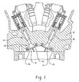
- FIG. 1 is a sectional view illustrating a valve assembly and its associated environment
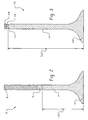
- FIG. 2 is a sectional view of a composite lightweight engine poppet valve according to a first embodiment of the present invention
- FIG. 3 is a sectional view of another embodiment of the engine poppet valve according to the present invention.
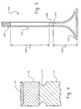
- FIG. 4 is a fragmentary sectional view depicting a tip portion of another embodiment according to the present invention.
- FIG. 5 is still another embodiment of the engine poppet valve according to the present invention.
- a typical engine poppet valve includes a valve head that has a flared fillet portion that transitions into a valve stem which terminates in a valve tip portion.
- valve head portion 12 includes a combustion face 22 that faces inwardly into an engine combustion chamber and a valve seat face 24 which is the peripheral surface that engages a cylinder head or a valve seat insert 26.
- the valve head portion 12 is manufactured with a predetermined diameter that depends upon the given internal combustion engine application as is known in the industry. It is further known in this art that an engine poppet valve can be solid, hollow, or partially solid/hollow.
- the present invention is directed to solid, hollow or partially solid/hollow valves, as will be described in further detail herein, to take advantage of unique material properties involved to achieve an optimum composite light weight valve.
- the engine poppet valve 10 is reciprocally received within the internal bore of a valve stem guide 30.
- valve stem guide 30 is depicted as a tubular or cylindrical structure which is inserted into a cylinder head 32 of the engine, it should be understood that alternative embodiments include the cylinder head itself functioning as a guide for the valve stem portion 14 without a separate tubular structure serving as the valve stem guide.
- the valve seat insert 26 cooperatively receives the valve seat face 24 to provide a sealing engagement. Since the operation of a poppet valve and a valve assembly within an internal combustion engine are well known in this art, further description and details concerning its operation are not included herein for the sake of brevity.
- the present invention resides in an improved composite lightweight engine poppet valve generally designated 10.
- the valve head 12 and at least a portion of the valve stem 14 are made of a light weight heat resistant material, preferably a titanium intermetallic material, and more preferably titanium aluminide (TiAl).
- TiAl valve stem 14 is attached to a heat treated nickel based alloy transition piece 16 that has high creep resistance via a solid state attachment.
- solid state attachment as used herein is intended to mean that very little of the material of the substrate is melted as opposed to fusion welding which inherently melts the substrate.
- Friction welding is the preferred method of making a solid state attachment in accordance with the present invention, but brazing and some other welding techniques may be employed as long as very little of the substrate is melted.
- the transition piece 16 is then further attached to the remainder of the valve stem and/or the tip portion 18 which are made from conventional valve materials known in the art.
- the attachment of the transition piece 16 to the conventional materials is made with any suitable attachment technique known in this art.
- the present invention employs preferably the solid valve head 12 and at least a portion of the stem portion 14 made of a titanium intermetallic material or compound, and preferably, titanium aluminide.
- a titanium intermetallic material is meant to include but not be limited to the following materials: titanium alloys, titanium aluminide (TiAl), and titanium.
- TiAl titanium aluminide
- the titanium aluminide material is commercially available and comprises titanium with approximately 30 to 50 weight percent aluminum.
- the aluminum content ranges from about 32% to about 35% with small amounts of iron and oxygen.
- the titanium intermetallic material offers high strength-to-weight ratio as well as excellent sulfidation resistance, good hot hardness, sufficient oxidation resistance, high thermal conductivity and low thermal expansion.
- sulfidation as used herein is the reaction of the metal or alloy with a sulfur-containing species to produce a sulfur compound that forms on or beneath the surface on the metal or alloy which eventually can lead to failure.
- valve head 12 is formed preferably by a casting process integrally with at least a part of stem portion 14.
- Valve head 12 and stem portion 14 may also be formed via a forging process or by powder metallurgy.
- Valve head 12 and stem portion 14 extend a selected distance (d1).
- the predetermined distance (d1) is selectable and may be any selected length.
- a longer stem portion 14 made of TiAl reduces the weight of the valve and reduces side loading of the poppet valve.
- side loading as used herein is intended to include but not be limited to the bending of the valve stem that occurs with the valve dynamics as the valve is operating or moving. In the preferred embodiment shown in Fig.
- the stem portion is of a selected length that places the attachment location of the TiAl valve stem to the transition piece 16 within the valve guide 30 in both the valve's closed and open positions. This length depends upon the given application, but is readily ascertainable to those skilled in this art. Typically, the length of the transition piece 16 ranges from about three to about thirteen millimeters (mm).
- an exhaust valve head for a 5.7 liter (L) engine has a diameter of about 39 mm, the length d1 of stem portion 14 is approximately eighty-six (86) mm, the diameter of the stem portion is approximately eight (8) mm and the diameter of the transition piece is about eight (8) mm, the axial length of the transition piece 16 is approximately three to four mm.
- the intake valve has similar dimensions except the diameter of the valve head is approximately fifty-six (56) mm.
- the diameter of the stem portion and the transition piece in the unfinished or rough condition is approximately nine (9) mm for the stem portion 14, and approximately ten and half (10.5) mm for the transition piece 16.
- Fig. 3 depicts another embodiment of engine poppet valve 110 in accordance with the present invention.
- the numeral designation "110” is employed simply to distinguish this embodiment from the first embodiment designated “10".
- the last two digits of the numeral designate like or similar features.
- This embodiment is quite similar to the first embodiment shown in Fig. 2, except that in this embodiment the length of the stem portion 114 is selected as distance d2 which is a longer length than d1.
- the longer stem length d2 offers more lightweight, heat resistant material throughout the majority of the stem portion 114 of engine poppet valve 110.
- the longer stem length d2 further reduces the weight of the poppet valve, and reduces side loading.
- the longer length of the stem does require more TiAl material, and is more expensive in terms of material and fabrication costs as mentioned earlier.
- the hardened steel valve tip material is a layer of a hardened conventional material 118 that is attached to the transition piece 116 in any of several ways which include but are not limited to weld cladding, coating, laser cladding powder material, or even a thermally sprayed deposit of a material like Eatonite 6 or Stellite 6.
- Eatonite is a federally registered trademark of Eaton Corporation.
- Stellite 6 is a federally registered trademark of Deloro Stellite Company.
- the deposited layer 118 has a preferred thickness of approximately 0.5 mm or less.
- the transition piece 116 is attached to the TiAl stem 114 immediately above the keeper groove 113 which is cut into the TiAl stem 114.
- Fig. 4 is a fragmentary enlarged sectional view of an alternate embodiment.
- the transition piece 116 includes a recessed area with a puddle of hardened conventional tip material used for the tip portion 118 in a layer with a thickness of approximately 0.5 mm or less.
- the joint between the transition piece 116 and the TiAl valve stem 114 is located at the top of the keeper groove 113 which has been cut into the TiAl valve stem 114.
- Fig. 5 depicts still another embodiment of the composite lightweight engine poppet valve 210 in accordance with the present invention.
- the valve head portion 212 is depicted as being hollow and is made of a titanium intermetallic material, preferably TiAl. It should be immediately apparent that valve head 212 may be solid as shown in Figs. 2 and 3.
- the valve heads 12, 112 depicted as being solid in Figs. 2 and 3 may be hollow.
- Valve head 212 includes a part of stem portion 214 made of a titanium intermetallic material formed integrally with valve head 212.
- Valve head 212 and stem portion 214 extend a selected distance (d3) which is a length that is selected based upon a desired application.
- Stem portion 214 is attached to one end of a heat treated nickel based alloy transition piece 216 having high creep resistance.
- a hollow tube 215 having a length (d4) is attached to the other end of transition piece 216.
- the tube 215 is the remaining portion of the stem portion and has the tip portion 218 attached thereto by conventional means including but not limited to welding, cladding, depositing, or the like. It should be understood that hollow tube 215 may be deep drawn and include a tip portion integrally therewith.
- the ratio of the length of d3/d4 is at a minimum about a 1/6 relationship of axial length, for example, d3 is twenty (20) mm and d4 is one hundred seventeen (117) mm.
- the remaining valve stem portion 215 may be made from a wide assortment of materials including but not limited to a titanium intermetallic material, a stainless steel material such as a 305 or 304 stainless steel that may be machined, extruded, or deep drawn, a martensitic stainless steel material, or a nickel base alloy.
- the transition piece 16, 116, 216 is a heat treated nickel base alloy with high creep resistance that is preferably solution treated, double aged, or even triple aged to maximize the materials creep resistance and deformation resistance to the TiAl material.
- the creep resistance of the transition piece 16, 116, 216 is at least 500 mega Pascals (mPa) at a temperature of approximately 650 degrees C after about 1000 hours.
- An exemplary heat treatment process includes but is not limited to the following: a solution treating temperature of about 1093 degrees C to about 1150 degrees C for a minimum of about twenty minutes, followed by air cooling to about room temperature; a first age hardening temperature of about 815 degrees C to about 870 degrees C for a minimum of about two hours, followed by air cooling to room temperature; a second age hardening temperature of about 704 degrees C to about 760 degrees C for a minimum of about two hours, followed by air cooling to room temperature; and a third age hardening temperature of about 650 degrees C to about 704 degrees C for a minimum of about two hours, followed by air cooling to room temperature. It should be understood that cooling may occur with water or oil quenching instead of air cooling.
- Suitable transition piece materials include but are not limited to Inconel 751, Waspaloy, and Udimet 720.
- Inconel is a federally registered trademark of Inco Alloys International, Inc.
- Udimet is a federally registered trademark of Special Metals Corporation.
- Waspaloy is a trademark of United Technologies Corp. It should be immediately apparent that other materials having a similar creep and deformation resistance to TiAl may be used with the present invention as a transition piece.
- the valve stem portion 14, 114, 214, 215 may be coated along its length with a coating that includes, but is not limited to, an ion nitride coating, a plasma carburized coating, thermal sprayed coatings, a chromium plated coating, a molybdenum sprayed coating, an Eatonite coating, physical vapor deposition (PVD) or chemical vapor deposition (CVD) type coatings or a nitride coating.
- a coating that includes, but is not limited to, an ion nitride coating, a plasma carburized coating, thermal sprayed coatings, a chromium plated coating, a molybdenum sprayed coating, an Eatonite coating, physical vapor deposition (PVD) or chemical vapor deposition (CVD) type coatings or a nitride coating.
- the tip portion 18, 118, 218 preferably is a solid, hardened material such as SAE 1547 or 8645 or Silchrome-1 Steel (Society of Automotive Engineers (SAE) J775 standard) material which is commercially available from commercial suppliers like Charter Steel or Crucible Steel for example.
- SAE Society of Automotive Engineers
- the tip portion 18, 118, 218 may be simply a conventional hardened steel material known in this art.
- the present invention provides a composite lightweight valve made with components that can be assembled rapidly. This makes the composite lightweight valve according to the present invention more economical to manufacture.
- the use of the titanium aluminide material yields excellent sulfidation resistance, good hot hardness, sufficient oxidation resistance, optimum mechanical strength, and high thermal conductivity along with lower thermal expansion.
- Another aspect of the present invention is directed to a method for making the composite lightweight engine valve.
- a significant aspect of the method according to the present invention is that the transition piece is attached first to the conventional material, and then to the TiAl valve stem with a solid state attachment. It should be apparent that this sequence may be reversed.
- the valve head portion 12, 112, 212 and stem portion 14, 114, 214 are formed preferably of titanium aluminide (TiAl) with a casting process.
- the TiAl castings are subjected to hot isostatic pressing (HIP) a process known to those of ordinary skill in this art that is used to remove centerline shrinkage and to close internal porosity.
- HIP hot isostatic pressing
- a conventional valve tip material like SAE 8645, with an axial length of about 50 mm or about two inches is preferably friction welded to a solution and heat treated Inconel 751 material with an axial length of about 50 mm or about two inches, or whatever length is required to enable the conventional tip material to be friction welded thereto.
- the Inconel 751 material is the transition piece 16, 116, 216 which is machined to an axial length of about 4 mm - 5 mm or about 0.180 inches.
- the term "machined” as used is intended to include but not be limited to cutting-off, taking down, turning or grinding the material.
- the transition piece is then preferably friction welded to the TiAl stem portion 14, 114, 214.
- the welding process is preferably a friction welding process with parameters as set forth below in Table 1.
- Friction Pressure Forging Pressure Friction Time Forging Time Rotational Speed Parameters P0 P1 P2 T0 T1 T2 (kg/mm 2 ) (kg/mm 2 ) (kg/mm 2 ) (sec) (sec) (rpm)
- P0 P1 P2 T0 T1 T2 (kg/mm 2 ) (kg/mm 2 ) (sec) (sec) (sec) (rpm)
- brazing inertia welding, direct drive welding, friction stir welding, resistance welding, magnetic pulse welding, or capacitor discharge welding.
Landscapes
- Engineering & Computer Science (AREA)
- Mechanical Engineering (AREA)
- General Engineering & Computer Science (AREA)
- Pressure Welding/Diffusion-Bonding (AREA)
- Lift Valve (AREA)
Applications Claiming Priority (2)
| Application Number | Priority Date | Filing Date | Title |
|---|---|---|---|
| US10/401,418 US6912984B2 (en) | 2003-03-28 | 2003-03-28 | Composite lightweight engine poppet valve |
| US401418 | 2003-03-28 |
Publications (2)
| Publication Number | Publication Date |
|---|---|
| EP1462621A1 EP1462621A1 (en) | 2004-09-29 |
| EP1462621B1 true EP1462621B1 (en) | 2006-10-04 |
Family
ID=32825016
Family Applications (1)
| Application Number | Title | Priority Date | Filing Date |
|---|---|---|---|
| EP04006685A Expired - Lifetime EP1462621B1 (en) | 2003-03-28 | 2004-03-19 | Composite lightweight engine poppet valve |
Country Status (4)
| Country | Link |
|---|---|
| US (1) | US6912984B2 (enExample) |
| EP (1) | EP1462621B1 (enExample) |
| JP (1) | JP4801324B2 (enExample) |
| DE (1) | DE602004002606T2 (enExample) |
Families Citing this family (42)
| Publication number | Priority date | Publication date | Assignee | Title |
|---|---|---|---|---|
| US20060118177A1 (en) * | 2004-12-07 | 2006-06-08 | Ucman Robert C | Coated valve and method of making same |
| DE102005013088B4 (de) * | 2005-03-18 | 2006-12-28 | Man B & W Diesel Ag | Gaswechselventil mit Korrosionsschutzschicht |
| DE102005015947B3 (de) * | 2005-04-07 | 2006-07-06 | Daimlerchrysler Ag | Reibschweißverfahren und Bauteile aus Stahl und Metallaluminid |
| JP2007032465A (ja) * | 2005-07-28 | 2007-02-08 | Nippon Steel Corp | 放熱性に優れた軽量エンジンバルブ |
| JP4298690B2 (ja) * | 2005-09-27 | 2009-07-22 | 本田技研工業株式会社 | エンジンバルブ及びその製造方法 |
| US20080000558A1 (en) * | 2006-06-30 | 2008-01-03 | Nan Yang | Friction welding |
| EP2047939A4 (en) * | 2006-08-02 | 2010-10-13 | Toshiba Kk | EROSION PREVENTION METHOD AND LINK WITH AN EROSION PREVENTION SECTION |
| US7847454B2 (en) * | 2007-03-08 | 2010-12-07 | General Electric Company | Encapsulated stator assembly and process for making |
| CA2691494C (en) | 2007-06-22 | 2016-07-12 | Tms India Private Limited | Dissimilar material bonding of drive shaft with flow control component of valve |
| US20090266870A1 (en) * | 2008-04-23 | 2009-10-29 | The Boeing Company | Joined composite structures with a graded coefficient of thermal expansion for extreme environment applications |
| US8512808B2 (en) | 2008-04-28 | 2013-08-20 | The Boeing Company | Built-up composite structures with a graded coefficient of thermal expansion for extreme environment applications |
| US8234788B2 (en) | 2008-05-13 | 2012-08-07 | GM Global Technology Operations LLC | Method of making titanium-based automotive engine valves |
| JP4390291B1 (ja) | 2008-09-18 | 2009-12-24 | 株式会社 吉村カンパニー | 中空エンジンバルブの弁傘部の製造方法及び中空エンジンバルブ |
| KR101123658B1 (ko) * | 2008-10-10 | 2012-03-22 | 니탄 밸브 가부시키가이샤 | 중공 포핏밸브 및 그 제조방법 |
| DE102008052247A1 (de) * | 2008-10-18 | 2010-04-22 | Mtu Aero Engines Gmbh | Bauteil für eine Gasturbine und Verfahren zur Herstellung des Bauteils |
| US8347908B2 (en) * | 2009-08-27 | 2013-01-08 | Honeywell International Inc. | Lightweight titanium aluminide valves and methods for the manufacture thereof |
| US8590516B2 (en) * | 2009-10-02 | 2013-11-26 | Robert Hull | Internal combustion engine |
| US20110168123A1 (en) * | 2010-01-12 | 2011-07-14 | Jay Carl Kerr | Engine valve for improved operating efficiency |
| US9103358B2 (en) * | 2010-03-16 | 2015-08-11 | Eaton Corporation | Corrosion-resistant position measurement system and method of forming same |
| JP2012107593A (ja) * | 2010-11-19 | 2012-06-07 | Hitachi Ltd | 蒸気タービンバルブ |
| KR101274239B1 (ko) * | 2010-12-02 | 2013-06-11 | 기아자동차주식회사 | 차량용 흡배기 밸브 |
| EP2740908B1 (en) * | 2012-06-14 | 2016-10-26 | Nittan Valve Co., Ltd. | Method of forming poppet valve faces and poppet valves having faces formed by this method |
| JP6251177B2 (ja) * | 2012-10-02 | 2017-12-20 | 日鍛バルブ株式会社 | 中空ポペットバルブ |
| JP5463439B1 (ja) | 2012-10-02 | 2014-04-09 | 日鍛バルブ株式会社 | 中空ポペットバルブ |
| EP2975229B1 (en) * | 2013-03-14 | 2020-10-28 | Nittan Valve Co., Ltd. | Hollow poppet valve |
| JP6131318B2 (ja) * | 2013-03-29 | 2017-05-17 | 日鍛バルブ株式会社 | 中空ポペットバルブ |
| WO2014155667A1 (ja) * | 2013-03-29 | 2014-10-02 | 日鍛バルブ株式会社 | 中空ポペットバルブ |
| US9920663B2 (en) | 2013-04-11 | 2018-03-20 | Nittan Valve Co., Ltd. | Hollow poppet valve |
| DE102013213268A1 (de) * | 2013-07-05 | 2015-01-08 | Mahle International Gmbh | Gebautes Hohlventil |
| DE102013216188A1 (de) * | 2013-08-14 | 2015-03-12 | Mahle International Gmbh | Leichtmetalleinlassventil |
| US20160348546A1 (en) * | 2014-02-12 | 2016-12-01 | Nittan Valve Co., Ltd. | Poppet valve |
| BR102014016213A2 (pt) * | 2014-06-30 | 2016-02-10 | Mahle Int Gmbh | válvula para motores de combustão interna e processo para obtenção de uma válvula |
| US9644504B2 (en) * | 2015-03-17 | 2017-05-09 | Caterpillar Inc. | Single crystal engine valve |
| DE102015116009C5 (de) * | 2015-09-22 | 2020-07-30 | Federal-Mogul Valvetrain Gmbh | Ventil für Verbrennungsmotoren mit Leitschaufel für Kühlmittel |
| DE102016200739A1 (de) * | 2016-01-20 | 2017-07-20 | Mahle International Gmbh | Metallisches Hohlventil für eine Brennkraftmaschine eines Nutzkraftfahrzeugs |
| JP6653050B1 (ja) | 2018-03-20 | 2020-02-26 | 日鍛バルブ株式会社 | 排気用中空ポペットバルブ |
| JP7190506B2 (ja) | 2018-11-12 | 2022-12-15 | 株式会社Nittan | エンジンのポペットバルブの製造方法 |
| KR102854811B1 (ko) * | 2019-12-06 | 2025-09-04 | 현대자동차주식회사 | 엔진 밸브의 제조방법 |
| EP4129525A4 (en) | 2020-03-30 | 2023-06-14 | Nittan Corporation | PROCESS FOR MAKING A MOTOR PIPET VALVE |
| KR102383576B1 (ko) * | 2022-02-07 | 2022-04-08 | 김종훈 | 고온, 고압용 콘트롤밸브의 pvd 코팅방법 |
| DE102023200287A1 (de) * | 2023-01-16 | 2024-08-01 | Mahle International Gmbh | Ventil für eine Brennkraftmaschine und Herstellungsverfahren |
| US20250354504A1 (en) * | 2024-05-15 | 2025-11-20 | Caterpillar Inc. | Tapered engine exhaust valve |
Family Cites Families (20)
| Publication number | Priority date | Publication date | Assignee | Title |
|---|---|---|---|---|
| JPS58151306U (ja) | 1982-04-05 | 1983-10-11 | 日産自動車株式会社 | 内燃機関の吸排気バルブ |
| JPS60211028A (ja) * | 1984-04-03 | 1985-10-23 | Daido Steel Co Ltd | 排気バルブ用合金 |
| JPS6182519A (ja) | 1984-09-29 | 1986-04-26 | Toshiba Corp | 位相回路 |
| JPS61275512A (ja) * | 1985-05-30 | 1986-12-05 | Nippon Kokan Kk <Nkk> | エンジン用部品及びその製造方法 |
| JPS62240408A (ja) * | 1986-04-10 | 1987-10-21 | Honda Motor Co Ltd | バルブ装置 |
| US5040501A (en) * | 1987-03-31 | 1991-08-20 | Lemelson Jerome H | Valves and valve components |
| JPS643007U (enExample) * | 1987-06-25 | 1989-01-10 | ||
| JPH0289535A (ja) * | 1988-09-24 | 1990-03-29 | Tobata Seisakusho:Kk | チタン系エンジンバルブの製造方法 |
| JPH05202706A (ja) * | 1992-01-29 | 1993-08-10 | Daido Steel Co Ltd | エンジンバルブおよびその製造方法 |
| US5458314A (en) | 1993-04-01 | 1995-10-17 | Eaton Corporation | Temperature control in an ultra light engine valve |
| US5413073A (en) | 1993-04-01 | 1995-05-09 | Eaton Corporation | Ultra light engine valve |
| US5441235A (en) | 1994-05-20 | 1995-08-15 | Eaton Corporation | Titanium nitride coated valve and method for making |
| US5517956A (en) * | 1994-08-11 | 1996-05-21 | Del West Engineering, Inc. | Titanium engine valve |
| US5823158A (en) | 1997-03-04 | 1998-10-20 | Trw Inc. | Engine valve and method for making the same |
| DE59707222D1 (de) | 1997-08-19 | 2002-06-13 | Trw Deutschland Gmbh | Hohlventil für Verbrennungsmotoren |
| JP3671271B2 (ja) * | 1997-10-03 | 2005-07-13 | 大同特殊鋼株式会社 | エンジン排気バルブの製造方法 |
| US20020005233A1 (en) * | 1998-12-23 | 2002-01-17 | John J. Schirra | Die cast nickel base superalloy articles |
| US6263849B1 (en) | 1999-07-20 | 2001-07-24 | Eaton Corporation | Ultra light engine valve and method of welding cap thereto |
| DE10031927A1 (de) | 2000-06-30 | 2002-01-24 | Daimler Chrysler Ag | Mehrteilig zusammengesetztes Leichtbauventil für Hubkolbenmaschinen |
| JP4895434B2 (ja) * | 2001-06-04 | 2012-03-14 | 清仁 石田 | 快削性Ni基耐熱合金 |
-
2003
- 2003-03-28 US US10/401,418 patent/US6912984B2/en not_active Expired - Lifetime
-
2004
- 2004-03-19 DE DE602004002606T patent/DE602004002606T2/de not_active Expired - Lifetime
- 2004-03-19 EP EP04006685A patent/EP1462621B1/en not_active Expired - Lifetime
- 2004-03-29 JP JP2004094264A patent/JP4801324B2/ja not_active Expired - Lifetime
Also Published As
| Publication number | Publication date |
|---|---|
| US6912984B2 (en) | 2005-07-05 |
| JP4801324B2 (ja) | 2011-10-26 |
| EP1462621A1 (en) | 2004-09-29 |
| DE602004002606D1 (de) | 2006-11-16 |
| US20040261746A1 (en) | 2004-12-30 |
| DE602004002606T2 (de) | 2007-08-16 |
| JP2004301124A (ja) | 2004-10-28 |
Similar Documents
| Publication | Publication Date | Title |
|---|---|---|
| EP1462621B1 (en) | Composite lightweight engine poppet valve | |
| US4834036A (en) | Composite valve for reciprocating engines and method for manufacturing the same | |
| US10443456B2 (en) | Exhaust valve for an internal combustion engine, and a method of strengthening an annular valve seat area in an exhaust valve | |
| JPH0258444B2 (enExample) | ||
| US5328527A (en) | Iron aluminum based engine intake valves and method of making thereof | |
| JP4208836B2 (ja) | ディーゼルエンジン内の燃料弁のためのノズル及び該ノズルを製造する方法。 | |
| JP5015393B2 (ja) | シート肉盛を施されたエンジンバルブおよびその製作方法 | |
| EP1441111B1 (en) | Light weight engine poppet valve | |
| JP2817121B2 (ja) | エンジン用タペットの製造方法 | |
| JPH05141213A (ja) | 内燃機関用吸・排気バルブ | |
| EP2318668B1 (en) | Cylinder head with valve seat and method for the production thereof | |
| JPH03149304A (ja) | アルミニウム合金製バルブリフタ | |
| EP3578282A1 (en) | Sliding member, and sliding member of internal combustion engine | |
| CN113843503B (zh) | 将气门座镶圈附接至铝制气缸盖的方法 | |
| JP5916829B1 (ja) | コンロッド、内燃機関、自動車両およびコンロッドの製造方法 | |
| JP2641424B2 (ja) | 内燃機関動弁装置の製造方法 | |
| CA3054677C (en) | Sliding member, and sliding member of internal combustion engine | |
| EP3623591B1 (en) | Valve for internal-combustion engines | |
| JPH11173113A (ja) | バルブリフタおよびその製造方法 | |
| JPH0152475B2 (enExample) | ||
| Beddoes | Valve materials and design | |
| JPH0441909A (ja) | エンジン用バルブおよびその製造方法 | |
| JPH06322583A (ja) | アルミニウム合金製バルブリフタの表面処理方法およびアルミニウム合金製バルブリフタ |
Legal Events
| Date | Code | Title | Description |
|---|---|---|---|
| PUAI | Public reference made under article 153(3) epc to a published international application that has entered the european phase |
Free format text: ORIGINAL CODE: 0009012 |
|
| AK | Designated contracting states |
Kind code of ref document: A1 Designated state(s): AT BE BG CH CY CZ DE DK EE ES FI FR GB GR HU IE IT LI LU MC NL PL PT RO SE SI SK TR |
|
| AX | Request for extension of the european patent |
Extension state: AL LT LV MK |
|
| 17P | Request for examination filed |
Effective date: 20050302 |
|
| 17Q | First examination report despatched |
Effective date: 20050414 |
|
| AKX | Designation fees paid |
Designated state(s): DE GB IT |
|
| GRAP | Despatch of communication of intention to grant a patent |
Free format text: ORIGINAL CODE: EPIDOSNIGR1 |
|
| GRAS | Grant fee paid |
Free format text: ORIGINAL CODE: EPIDOSNIGR3 |
|
| GRAA | (expected) grant |
Free format text: ORIGINAL CODE: 0009210 |
|
| AK | Designated contracting states |
Kind code of ref document: B1 Designated state(s): DE GB IT |
|
| PG25 | Lapsed in a contracting state [announced via postgrant information from national office to epo] |
Ref country code: IT Free format text: LAPSE BECAUSE OF FAILURE TO SUBMIT A TRANSLATION OF THE DESCRIPTION OR TO PAY THE FEE WITHIN THE PRESCRIBED TIME-LIMIT;WARNING: LAPSES OF ITALIAN PATENTS WITH EFFECTIVE DATE BEFORE 2007 MAY HAVE OCCURRED AT ANY TIME BEFORE 2007. THE CORRECT EFFECTIVE DATE MAY BE DIFFERENT FROM THE ONE RECORDED. Effective date: 20061004 |
|
| REG | Reference to a national code |
Ref country code: GB Ref legal event code: FG4D |
|
| REF | Corresponds to: |
Ref document number: 602004002606 Country of ref document: DE Date of ref document: 20061116 Kind code of ref document: P |
|
| PLBE | No opposition filed within time limit |
Free format text: ORIGINAL CODE: 0009261 |
|
| STAA | Information on the status of an ep patent application or granted ep patent |
Free format text: STATUS: NO OPPOSITION FILED WITHIN TIME LIMIT |
|
| 26N | No opposition filed |
Effective date: 20070705 |
|
| REG | Reference to a national code |
Ref country code: GB Ref legal event code: 732E Free format text: REGISTERED BETWEEN 20181115 AND 20181130 |
|
| REG | Reference to a national code |
Ref country code: DE Ref legal event code: R082 Ref document number: 602004002606 Country of ref document: DE Ref country code: DE Ref legal event code: R081 Ref document number: 602004002606 Country of ref document: DE Owner name: EATON INTELLIGENT POWER LIMITED, IE Free format text: FORMER OWNER: EATON CORP., CLEVELAND, OHIO, US |
|
| PGFP | Annual fee paid to national office [announced via postgrant information from national office to epo] |
Ref country code: FR Payment date: 20190325 Year of fee payment: 16 Ref country code: GB Payment date: 20190222 Year of fee payment: 16 |
|
| GBPC | Gb: european patent ceased through non-payment of renewal fee |
Effective date: 20200319 |
|
| PG25 | Lapsed in a contracting state [announced via postgrant information from national office to epo] |
Ref country code: GB Free format text: LAPSE BECAUSE OF NON-PAYMENT OF DUE FEES Effective date: 20200319 |
|
| PG25 | Lapsed in a contracting state [announced via postgrant information from national office to epo] |
Ref country code: IT Free format text: LAPSE BECAUSE OF NON-PAYMENT OF DUE FEES Effective date: 20200319 |
|
| PGFP | Annual fee paid to national office [announced via postgrant information from national office to epo] |
Ref country code: DE Payment date: 20230221 Year of fee payment: 20 |
|
| P01 | Opt-out of the competence of the unified patent court (upc) registered |
Effective date: 20230521 |
|
| REG | Reference to a national code |
Ref country code: DE Ref legal event code: R071 Ref document number: 602004002606 Country of ref document: DE |