WO2014155667A1 - 中空ポペットバルブ - Google Patents
中空ポペットバルブ Download PDFInfo
- Publication number
- WO2014155667A1 WO2014155667A1 PCT/JP2013/059529 JP2013059529W WO2014155667A1 WO 2014155667 A1 WO2014155667 A1 WO 2014155667A1 JP 2013059529 W JP2013059529 W JP 2013059529W WO 2014155667 A1 WO2014155667 A1 WO 2014155667A1
- Authority
- WO
- WIPO (PCT)
- Prior art keywords
- valve
- diameter hollow
- hollow portion
- small
- coolant
- Prior art date
Links
Images


Classifications
-
- F—MECHANICAL ENGINEERING; LIGHTING; HEATING; WEAPONS; BLASTING
- F01—MACHINES OR ENGINES IN GENERAL; ENGINE PLANTS IN GENERAL; STEAM ENGINES
- F01L—CYCLICALLY OPERATING VALVES FOR MACHINES OR ENGINES
- F01L3/00—Lift-valve, i.e. cut-off apparatus with closure members having at least a component of their opening and closing motion perpendicular to the closing faces; Parts or accessories thereof
- F01L3/12—Cooling of valves
- F01L3/14—Cooling of valves by means of a liquid or solid coolant, e.g. sodium, in a closed chamber in a valve
-
- B—PERFORMING OPERATIONS; TRANSPORTING
- B21—MECHANICAL METAL-WORKING WITHOUT ESSENTIALLY REMOVING MATERIAL; PUNCHING METAL
- B21K—MAKING FORGED OR PRESSED METAL PRODUCTS, e.g. HORSE-SHOES, RIVETS, BOLTS OR WHEELS
- B21K1/00—Making machine elements
- B21K1/20—Making machine elements valve parts
- B21K1/22—Making machine elements valve parts poppet valves, e.g. for internal-combustion engines
-
- B—PERFORMING OPERATIONS; TRANSPORTING
- B23—MACHINE TOOLS; METAL-WORKING NOT OTHERWISE PROVIDED FOR
- B23P—METAL-WORKING NOT OTHERWISE PROVIDED FOR; COMBINED OPERATIONS; UNIVERSAL MACHINE TOOLS
- B23P15/00—Making specific metal objects by operations not covered by a single other subclass or a group in this subclass
- B23P15/001—Making specific metal objects by operations not covered by a single other subclass or a group in this subclass valves or valve housings
- B23P15/002—Making specific metal objects by operations not covered by a single other subclass or a group in this subclass valves or valve housings poppet valves
Definitions
- the present invention relates to a hollow poppet valve in which a coolant is loaded together with an inert gas in a hollow portion formed from an umbrella portion to a shaft portion of the poppet valve.
- a hollow part is formed from the umbrella part of the poppet valve integrally formed on one end side of the shaft part to the shaft part, and has a higher thermal conductivity than the base material of the valve.
- a hollow poppet valve is described in which a coolant (eg, metallic sodium, melting point about 98 ° C.) is loaded into the hollow portion with an inert gas.
- the thermal conductivity of the valve (hereinafter referred to as the heat extraction effect of the valve) can be improved. it can.
- the combustion chamber becomes hot due to the driving of the engine, but if the temperature of the combustion chamber is too high, knocking occurs and a predetermined engine output cannot be obtained, leading to deterioration of fuel consumption (deterioration of engine performance). Therefore, as a method of actively conducting heat generated in the combustion chamber through the valve in order to lower the temperature of the combustion chamber (a method for increasing the heat-sucking effect of the valve), the coolant is hollowed together with the inert gas.
- Various hollow valves loaded in the box have been proposed.
- the communication part between the disk-shaped large-diameter hollow part in the umbrella part and the linear small-diameter hollow part in the shaft part is constituted by a smooth curved area (transition area where the inner diameter gradually changes).
- this communicating part has a smoothly continuous shape, the coolant (liquid) together with the enclosed gas and the large-diameter hollow part during the opening / closing operation of the valve (reciprocating operation in the axial direction of the valve) It is thought that it can move smoothly between the small-diameter hollow portions, and the heat-drawing effect of the valve is improved.
- the coolant (liquid) moves smoothly between the large-diameter hollow part and the small-diameter hollow part according to the opening / closing operation of the valve.
- the coolant (liquid) in the hollow portion moves in the axial direction in a state where the upper layer portion, the middle layer portion, and the lower layer portion are maintained in a vertical relationship without being stirred.
- the linear small-diameter hollow portion in the valve shaft portion is communicated so as to be substantially orthogonal to the ceiling surface of the frustoconical large-diameter hollow portion in the valve umbrella portion, and the large-diameter hollow portion to the small-diameter hollow portion.
- Patent Document 3 has a structure in which a linear small-diameter hollow portion communicates with a ceiling surface of a large-diameter hollow portion having a truncated cone shape, and a part of the coolant has a communicating portion when the valve is opened and closed. Therefore, the momentum of the tumble flow formed on the coolant in the large-diameter hollow portion is weakened accordingly. For this reason, the coolant is not sufficiently agitated, and the heat drawing effect (thermal conductivity) is not sufficiently exhibited (first problem).
- Patent Document 3 “By forming the large-diameter hollow portion in the valve umbrella portion into a substantially truncated cone shape, the valve in the large-diameter hollow portion is opened and closed during the opening / closing operation. Assuming the configuration of ⁇ forming a tumble flow in the coolant '', a pipe-shaped partition wall is provided between the ceiling surface and the bottom surface of the large-diameter hollow portion, and the small-diameter hollow portion is replaced with the bottom surface of the large-diameter hollow portion (valve umbrella surface).
- the coolant in both hollow parts will be in the hollow part when the valve is opened and closed.
- the inertial force acting on the coolant is used only for the formation of the tumble flow, so that the momentary tumble flow is smoothly formed, as described above.
- the first problem can be solved and the heat of the valve umbrella Part by being directly transmitted to the valve shaft via the coolant in the small-diameter hollow portion, also can be solved second problem mentioned above, were considered.
- the present invention has been made on the basis of the above-mentioned knowledge of the inventor with respect to the prior art document.
- the purpose of the present invention is to provide a pipe-shaped partition wall in the large-diameter hollow portion in the valve umbrella portion and to provide a small-diameter hollow portion in the valve shaft portion.
- An object of the present invention is to provide a hollow poppet valve that extends to the bottom surface of the large-diameter hollow portion (the back side of the front surface of the valve umbrella) and is separated from the large-diameter hollow portion, thereby improving the heat pulling effect.
- a hollow portion is formed from the umbrella portion of the poppet valve integrally formed on one end side of the shaft portion to the shaft portion.
- the hollow poppet valve in which the hollow portion is filled with a coolant together with an inert gas A substantially frustoconical large-diameter hollow portion having a tapered outer peripheral surface that substantially follows the outer shape of the umbrella portion is provided in the valve umbrella portion, and the ceiling surface of the large-diameter hollow portion is provided in the valve shaft portion.
- a linear small-diameter hollow portion that communicates substantially orthogonally to The small-diameter hollow portion is extended to the bottom surface of the large-diameter hollow portion (the back side of the valve umbrella) between the bottom surface of the large-diameter hollow portion and the ceiling surface, and the small-diameter hollow portion is separated from the large-diameter hollow portion.
- a pipe-shaped partition wall is interposed, and both separated hollow parts are filled with an inert gas and a coolant, respectively.
- the small-diameter hollow portion is interposed between the bottom surface of the large-diameter hollow portion and the ceiling surface, and the small-diameter hollow portion is extended to the bottom surface of the large-diameter hollow portion (the back side of the valve umbrella front).
- the pipe-shaped partition wall is separated from the valve shaft side, and the pipe-shaped partition wall is integrated with the structure of the pipe-shaped partition wall as shown in the second embodiment. It is conceivable that a pipe-shaped partition wall is integrated with the back side of the cap constituting the.
- the amount of coolant loaded in the hollow portion is superior in the heat-drawing effect (thermal conductivity), but as the amount increases, the heat-drawing effect on the loaded amount does not increase, and particularly in the large-diameter hollow portion. If the amount of the coolant to be charged is too large, it is difficult to form a tumble flow. Therefore, the amount of coolant to be charged is preferably about 1/2 to 4/5 of the volume of each hollow portion.
- the large-diameter hollow portion in the valve umbrella portion has a tapered outer peripheral surface that substantially follows the outer shape of the umbrella portion, and is formed in an annular substantially truncated cone shape having a pipe-shaped partition wall as the inner peripheral surface.
- the inertial force (upward) acting on the coolant near the center of the large-diameter hollow portion is larger than the inertial force acting on the coolant near the periphery of the large-diameter hollow portion.
- the flow F1 which goes to a radial direction outer side along a ceiling surface from the large diameter hollow part center vicinity generate
- the coolant near the center of the large-diameter hollow portion moves upward, so that the bottom surface side near the center of the large-diameter hollow portion becomes negative pressure, from the radially outer side to the inner side.
- a flowing flow F3 is generated, and accompanying this, a downward flow F2 is generated along the tapered outer peripheral surface of the large-diameter hollow portion.
- a swirling flow (hereinafter referred to as an outer tumble flow) T1 is formed around the central axis of the valve. Is done.
- the entire coolant that has moved upward when the valve shifts from the open state to the closed state moves smoothly downward.
- the inertial force (downward) acting on the coolant near the center of the large-diameter hollow portion is inertia acting on the coolant near the large-diameter hollow portion as shown in FIG. Greater than power.
- the flow F6 which goes to a radial direction outward along a bottom face from the large diameter hollow part center side generate
- a swirling flow (hereinafter referred to as an inner tumble flow) T2 is formed around the central axis of the valve in the large-diameter hollow portion coolant. Is done.
- the tumble flow T1, T2 shown in FIG. 3 is formed in the coolant in the large-diameter hollow portion of the valve, and the upper layer portion of the coolant in the entire large-diameter hollow portion, Since the middle layer portion and the lower layer portion are actively stirred, the heat drawing effect (thermal conductivity) of the valve is remarkably improved.
- the inertial force acting on the coolant is used only for the formation of the tumble flow, so that a vigorous tumble flow is formed smoothly, the coolant is sufficiently stirred, and the heat in the valve umbrella portion The pulling effect is increased.
- the inner peripheral surface of the valve shaft portion defining the small-diameter hollow portion and the inner peripheral surface of the pipe-shaped partition wall are configured to be flush with each other.
- the entire coolant in the small-diameter hollow portion moves smoothly in the axial direction during the opening / closing operation (vertical movement operation) of the valve, and the coolant in the large-diameter hollow portion.
- the whole is actively stirred by the tumble flow, and most of the heat on the valve head is efficiently transferred to the valve head through the coolant in the large-diameter hollow part, and part of the heat on the valve head is also transferred. Since it is directly transmitted to the valve shaft through the coolant in the small-diameter hollow portion, the heat pulling effect (thermal conductivity) in the valve umbrella is remarkably improved, and the performance of the engine is improved.
- the heat transfer efficiency by the coolant in the small-diameter hollow portion is increased by the amount of smooth movement of the coolant in the small-diameter hollow portion in the axial direction, and the heat drawing effect (thermal conductivity) of the valve is increased. Further improvement.
- the coolant in the small-diameter hollow portion is also actively agitated with the opening / closing operation (vertical operation) of the valve, the heat drawing effect (thermal conductivity) of the valve is further improved. Is done.
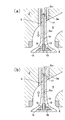
- FIG. 1 It is a longitudinal cross-sectional view of the hollow poppet valve which is the 1st Example of this invention. It is a figure which shows the inertial force which acts on the coolant in the hollow part at the time of the same hollow poppet valve reciprocatingly, (a) shows the inertial force which acts on the coolant at the time of valve opening operation
- (C) is a hole drilling step for drilling a hole corresponding to a small-diameter hollow portion near the shaft end
- (d) is a step forming step for forming a step for press-fitting a partition wall
- (e) is a shaft end member.
- (F) is a partition press-fitting and brazing step for press-fitting and brazing the partition wall
- (g) is a coolant filling step for filling the coolant into the small-diameter hollow portion and the large-diameter hollow portion, respectively
- ( h) is a diagram showing a step of joining a cap to an opening of a concave portion (large diameter hollow portion) of the umbrella outer shell (large diameter hollow portion sealing step).
- FIG. 1 It is a longitudinal cross-sectional view of the hollow poppet valve which is the 2nd Example of this invention.
- the manufacturing process of the hollow poppet valve is shown, (a) is a hot forging process for forging a shell which is an intermediate product of the valve, (b) is a hole drilling process for drilling a hole corresponding to a small-diameter hollow part, (c ) Is a step portion forming step for forming a step portion for press-fitting a partition wall into the opening of the hole, (d) is a coolant filling step for filling the small diameter hollow portion and the large diameter hollow portion with a coolant, and (e) is a cap.
- FIG. 1 to 4 show a hollow poppet valve for an internal combustion engine according to a first embodiment of the present invention.
- reference numeral 10 denotes a heat resistant structure in which a valve umbrella portion 14 is integrally formed on one end side of a valve shaft portion 12 extending straight through an R-shaped fillet portion 13 whose outer diameter gradually increases.
- a tapered face portion 16 is provided on the outer periphery of the valve umbrella portion 14.
- a large-diameter hollow portion S1 in the valve umbrella portion 14 and a small-diameter hollow portion S2 in the valve shaft portion 12 are disposed so as to be orthogonal to each other.
- Each of the hollow portions S1 and S2 is filled with a coolant 19 together with an inert gas.
- the outer diameter of the large-diameter hollow portion S1 is formed in a truncated cone shape having a circular outer peripheral surface 14b2 that substantially follows the circular ceiling surface 14b1 and the outer shape of the valve umbrella portion 14, and the small-diameter hollow portion S2 is formed in the valve shaft portion 12. And is formed in a long and narrow cylindrical shape coaxial.
- the small-diameter hollow portion S2 in the valve shaft portion 12 is a circle that is fixedly integrated with an opening portion of the small-diameter hollow portion S2 to the large-diameter hollow portion S2, and the tip portion is in pressure contact with the bottom surface of the large-diameter hollow portion S2.
- the pipe-shaped partition wall 15 extends to the bottom surface of the large-diameter hollow portion S2.
- the large-diameter hollow portion S2 has an annular space (tapered outer peripheral surface 14b2 and circular-pipe-shaped partition wall 15 surrounding the circular pipe-shaped partition wall 15 that defines the extended lower end of the small-diameter hollow portion S2. Is an annular, generally frustoconical space).
- the small-diameter hollow portion S2 in the valve shaft portion 12 penetrates the large-diameter hollow portion S2 by the circular pipe-shaped partition wall 15 interposed between the ceiling surface 14b1 and the bottom surface of the large-diameter hollow portion S2.
- the large-diameter hollow portion S2 defined around the partition wall 15 is separated.
- a shaft-integrated shell (hereinafter simply referred to as a shell) 11 is a valve intermediate product in which an umbrella outer shell 14a is integrally formed on one end side of a shaft portion 12a in which a hole corresponding to the small-diameter hollow portion S2 is formed. And a circular pipe-like partition wall 15 fixed and integrated with the opening of the small-diameter hollow portion S2 in the recess 14b of the umbrella outer shell 14a, and the opening-side inner peripheral surface 14c of the recess 14b of the umbrella outer shell 14a.
- the large-diameter hollow portion S1 in the valve umbrella portion 14 and the inside of the valve shaft portion 12 are formed by the disc-shaped cap 18 constituting the valve umbrella surface 18a and the shaft end member 12b axially contacted with the shaft portion 12a of the shell 11.
- the hollow poppet valve 10 from which the small-diameter hollow portion S2 is separated is configured, and the hollow portions S1 and S2 are loaded with a coolant 19 such as metallic sodium together with an inert gas such as argon gas.
- a coolant 19 such as metallic sodium
- an inert gas such as argon gas
- the amount of coolant loaded in the hollow portion is superior in the heat-drawing effect (thermal conductivity), but as the amount increases, the heat-drawing effect on the loaded amount does not increase, and particularly in the large-diameter hollow portion. If the amount of the coolant to be charged is too large, it is difficult to form a tumble flow. Therefore, the amount of coolant to be charged is preferably about 1/2 to 4/5 of the volume of each hollow portion.
- the opening of the small-diameter hollow portion S2 that opens into the recess 14b (the circular bottom 14b1) of the umbrella outer shell 14a that defines the large-diameter hollow portion S1 has a thickness and press-fitting allowance for the pipe-shaped partition wall 15. Is formed, and the inner peripheral surface of the partition wall 15 press-fitted and fixed to the step portion 15a is the inner periphery of the linear small-diameter hollow portion S2 in the valve shaft portion 12.
- the amount of protrusion of the partition wall 15 into the large-diameter hollow portion S1 is set so as to be in pressure contact with the cap 18 that defines the bottom surface of the large-diameter hollow portion S1.
- reference numeral 2 denotes a cylinder head
- reference numeral 6 denotes an exhaust passage extending from the combustion chamber 4.
- An annular valve seat 8 provided with 8a is provided.
- Reference numeral 3 denotes a valve insertion hole provided in the cylinder head 2, and the valve insertion hole 3 includes a cylindrical valve guide 3 a with which the shaft portion 12 of the valve 10 is slidably contacted.
- Reference numeral 9 is a valve spring that urges the valve 10 in the valve closing direction (upward in FIG. 1)
- reference numeral 12 c is a cotter groove provided at the end of the valve shaft 12.
- the shell 11 and the cap 18 that are exposed to the high-temperature gas in the combustion chamber 4 and the exhaust passage 6 are made of heat-resistant steel.
- the shaft end member 12b that does not require as much heat resistance as 18 is made of a general steel material.
- the coolant 19 in the large-diameter hollow portion S1 moves in the vertical direction by the acting inertial force.
- tumble flows T1 and T2 are formed, and the upper layer portion, middle layer portion, and lower layer portion of the coolant 19 are actively stirred.
- the heat drawing effect (thermal conductivity) of the umbrella portion 14 of the valve 10 is greatly improved.
- the small-diameter hollow portion S2 includes a small-diameter hollow portion S21 near the valve shaft end portion having a relatively large inner diameter d1 and a small-diameter hollow portion S22 near the valve umbrella portion 14 having a relatively small inner diameter d2 (d2 ⁇ d1).
- An annular stepped portion 17 is formed between the small-diameter hollow portions S21 and S22, and the coolant 19 is loaded up to a position beyond the stepped portion 17.
- the large-diameter hollow portion S1 is formed in an annular substantially truncated cone shape having a circular pipe-shaped partition wall 15 as an inner peripheral surface and a tapered outer peripheral surface 14b2 substantially following the outer shape of the umbrella portion 14. Therefore, as shown in FIG. 2A, the inertial force (upward) acting on the coolant near the center of the large-diameter hollow portion S1 is larger than the inertial force acting on the coolant near the periphery of the large-diameter hollow portion. For this reason, as shown to Fig.3 (a), the flow F1 which goes to a radial direction outer side along the ceiling surface 14b1 generate
- the outer tumble flow T1 is formed around the central axis L of the valve, as indicated by arrows F1, F2, F3, and F1, in the coolant 19 in the large-diameter hollow portion S1.
- the inertial force (downward) acting on the coolant 19 near the center of the large-diameter hollow portion S1 is, as shown in FIG. 2B, the coolant 19 near the large-diameter hollow portion S1. Greater than the inertial force acting on For this reason, as shown in FIG.3 (b), in the coolant 19 in large diameter hollow part S1, the flow F6 which goes to a radial direction outer side along the bottom face from large diameter hollow part S1 center generate
- an inward tumble flow T2 is formed around the central axis L of the valve 10 in the coolant 19 of the large-diameter hollow portion S1, as indicated by arrows F6 ⁇ F7 ⁇ F8 ⁇ F6.
- the coolant 19 in the small-diameter hollow portion S2 of the valve 10 is agitated by the turbulent flows F9 and F10 generated when the valve 10 opens and closes, and the coolant 19 in the large-diameter hollow portion S1 of the valve 10 is stirred. Since the upper layer portion, the middle layer portion, and the lower layer portion are actively stirred by the tumble flows T1 and T2 formed when the valve 10 is opened and closed, the heat drawing effect (thermal conductivity) of the valve 10 is remarkably increased. Has been enhanced.
- the stepped portion 17 in the small-diameter hollow portion S is provided at a position substantially corresponding to the end portion 3 b facing the exhaust passage 6 of the valve guide 3 and has a shaft end portion having a large inner diameter.
- the stepped portion 17 in the small-diameter hollow portion S2 has a predetermined position (in the valve shaft portion 12) that does not enter the exhaust passage 6 when the valve 10 is fully opened (lowered), as indicated by the phantom line in FIG.
- the thin-walled small-diameter hollow portion S21 forming wall is provided at a predetermined position in the valve insertion hole 3 that is not easily affected by heat in the exhaust passage 6.
- Reference numeral 17X in FIG. 1 indicates the position of the stepped portion 17 in a state where the valve 10 is fully opened (lowered).
- the region near the valve umbrella portion 14 in the valve shaft portion 12 that is always in the exhaust passage 6 and exposed to high heat reduces the fatigue strength. It must be formed to a thickness that can withstand.
- heat from the combustion chamber 4 and the exhaust passage 6 is transmitted via the coolant 19.
- the transmitted heat is immediately radiated to the cylinder head 2 through the valve guide 3a, the temperature does not become as high as that near the valve umbrella portion 14.
- the inner diameter of the small-diameter hollow portion S21 is increased, and first, the surface area of the entire small-diameter hollow portion S2 (contact area with the coolant 19) is increased, so that the valve shaft portion 12 Heat transfer efficiency is increased. Secondly, the total weight of the valve 10 is reduced by increasing the volume of the entire small-diameter hollow portion S2.
- the valve 10 can be provided at low cost by using an inexpensive material having lower heat resistance than the material of the shell 11.
- an umbrella outer shell 14a provided with a truncated cone-shaped concave portion 14b corresponding to the large-diameter hollow portion S1 and a shaft portion 12a were integrally formed by hot forging.
- the shell 11 is formed.
- a bottom surface 14b1 of the concave portion 14b of the umbrella outer shell 14a is formed by a plane orthogonal to the shaft portion 12a (the central axis L of the shell 11).
- a hot forging process after forging a spherical part at the end of a heat-resistant steel bar with an extruding forging to manufacture the shell 11 from a heat-resistant steel block or an upsetter by extrusion forging that sequentially replaces the mold, Any of upsetting forging which forges shell 11 (umbrella outer shell 14a) using a metal mold may be used.
- an R-shaped fillet portion 13 is formed between the umbrella outer shell 14a and the shaft portion 12a of the shell 11, and a tapered face portion is formed on the outer peripheral surface of the umbrella outer shell 14a. 16 is formed.
- the shell 11 is arranged so that the concave portion 14b of the umbrella outer shell 14a faces upward, and the small hollow portion closer to the umbrella from the concave portion 14b side of the umbrella outer shell 14a.
- the circular hole 14e corresponding to S22 is drilled by drilling (hole drilling step).
- a circular hole 14f corresponding to the small-diameter hollow portion S21 near the shaft end is drilled from the end of the shaft 12a (hole drilling step).
- a step portion 15a for press-fitting the partition wall 15 is formed on the opening side of the circular hole 14e in the concave portion 14b of the umbrella outer shell 14a by cutting or drilling ( Stepped portion forming step).
- the shaft end member 12b is axially contacted with the shaft portion 12a of the shell 11 (shaft end member axial contact step).
- a pipe-shaped partition wall 15 is press-fitted into the stepped portion 15a of the circular hole 14e opened in the concave portion 14b of the umbrella outer shell 14a, and brazed as necessary ( Bulkhead press-fitting and brazing process).
- a cap 18 is arranged in the concave portion 14b (the inner peripheral surface 14c of the opening side) of the umbrella outer shell 14a in an argon gas atmosphere, and the tip of the pipe-shaped partition wall 15 is placed.
- the cap 18 is joined to the recess 14b of the umbrella outer shell 14a (for example, resistance joining) in a state where the cap 18 is pressed and held on the part, and the large-diameter hollow part S1 is sealed (large-diameter hollow part sealing step).
- the valve 10 is completed by performing processing for forming the cotter groove 12c at the shaft end.
- electron beam welding, laser welding, or the like may be employed instead of resistance joining.
- FIG. 5 and 6 show a hollow poppet valve according to a second embodiment of the present invention.
- a circular pipe-like shape fixed to and integrated with the opening (step portion 15a) of the small-diameter hollow portion S2 that opens into the recess 14b of the umbrella outer shell 14a of the shell 11.
- the partition wall 15 extends the small-diameter hollow portion S2 in the valve shaft portion 12 to the bottom surface of the large-diameter hollow portion S1 (the back surface of the cap 18), and separates the small-diameter hollow portion S2 from the large-diameter hollow portion S1.
- the small-diameter hollow portion S2 ′ is extended to the bottom surface of the large-diameter hollow portion S1 (the back surface of the cap 18) on the back side of the cap 18 constituting the valve head 18a.
- a circular pipe-shaped partition wall 15A that separates the small-diameter hollow portion S2 ′ from the large-diameter hollow portion S1 is fixed and integrated.
- a pipe-shaped partition wall 15A is fixed and integrated on the back surface side of the cap 18 by brazing or welding, for example, while the small-diameter hollow portion S2 ′ in the shell 11A (the concave portion 14b of the umbrella outer shell 14a).
- a step 15b is formed in which the tip of a pipe-shaped partition wall 15A integrated with the cap 18 can be press-fitted.
- the cap 18 is in the recess 14b (opening inner periphery 14c of the umbrella outer shell 14a of the shell 11A).
- the large-diameter hollow portion S1 is hermetically sealed.
- the distal end portion of the pipe-shaped partition wall 15A is press-fitted and held in the step portion 15b of the small-diameter hollow portion S2 ', so that the small-diameter hollow portion S2' separated from the large-diameter hollow portion S1 is also sealed.
- a coolant 19 such as metallic sodium is loaded together with an inert gas such as argon gas.
- the inner peripheral surface of the partition wall 15A press-fitted and fixed to the step portion 15b is flush with the inner peripheral surface of the linear small-diameter hollow portion S2 ′ in the valve shaft portion 12, so that the valve 10A opens and closes.
- the coolant 19 in the small-diameter hollow portion S2 ′ can move smoothly in the vertical direction.
- the small-diameter hollow portion S2 ′ of the valve 10A of the present embodiment is configured with a constant inner diameter in the axial direction, and there is no stepped portion 17 formed in the small-diameter hollow portion S2 of the valve 10 of the first embodiment. Therefore, when the valve 10A is opened and closed, no turbulent flow is generated in the coolant 19 in the small diameter hollow portion S2 ′.
- a shell 11A in which an umbrella outer shell 14a provided with a truncated cone-shaped recess 14b and a valve shaft portion 12 are integrally formed is formed by hot forging.
- the shell 11A is arranged so that the concave portion 14b of the umbrella outer shell 14a faces upward, and corresponds to the small-diameter hollow portion S2 ′ from the concave portion 14b side of the umbrella outer shell 14a.
- the circular hole 14e 'to be drilled is drilled (hole drilling step).
- a step 15b for press-fitting the pipe-shaped partition wall 15A into the opening of the circular hole 14e 'in the recess 14b of the umbrella outer shell 14a is cut or drilled. (Partition wall press-fitting hole forming step).
- a predetermined amount of coolant (solid) 19 is filled in the circular holes 14e 'and the recesses 14b of the umbrella outer shell 14a (coolant filling step). Since the coolant (solid) 19 is in the form of clay at normal temperature, it can be inserted into the circular hole 14e 'in the form of a thin rod, or it can be filled in a predetermined position in the recess 14b of the umbrella outer shell 14a. .
- the pipe 18 is inserted into the stepped portion 15b of the circular hole 14e 'in the concave portion 14b of the umbrella outer shell 14a while press fitting the pipe-shaped partition wall 15A under an argon gas atmosphere. It arrange
- the valve 10A is completed by performing processing for forming the cotter groove 12c at the shaft end.
- the step of drilling a hole corresponding to the small-diameter hollow portion S2 ′ may be performed in one step. Furthermore, the process of manufacturing the valve is simplified, for example, the process of axially contacting the shaft end member is not required.
- the small diameter hollow portion S2 is interposed between the bottom surface of the large diameter hollow portion S1 and the ceiling surface, and extends to the bottom surface of the large diameter hollow portion S1 (the back side of the valve umbrella front).
- the pipe-shaped partition that separates the hollow part S2 from the large-diameter hollow part S1 is composed of circular pipe-shaped partition walls 15 and 15A, but is composed of a bellows-structured pipe-shaped partition that can expand and contract in the axial direction. You may make it interpose in the form compressed to the axial direction between the bottom face and ceiling surface of large diameter hollow part S1.
Landscapes
- Engineering & Computer Science (AREA)
- Mechanical Engineering (AREA)
- Chemical & Material Sciences (AREA)
- Combustion & Propulsion (AREA)
- General Engineering & Computer Science (AREA)
- Lift Valve (AREA)
Abstract
バルブ軸部内の小径中空部をバルブ傘部内の大径中空部の底面まで延長することで、中空ポペットバルブの熱引き効果を改善する。傘部(14)内の円錐台形状の大径中空部(S1)が軸部(12)内の小径中空部(S2)に連通する中空ポペットバルブ(10)で、中空部(S2)を中空部(S1)の底面(キャップ(18)の裏側)まで延長するパイプ状の隔壁(15)を中空部(S1)内に設けて、中空部(S1,S2)を分 離し、両中空部(S1,S2)に不活性ガス,冷却材(19)をそれぞれ装填する。バルブ(10)の開閉動作の際に中空部(S1)の冷却材(19)に作用する慣性力がタンブル流の形成にのみ利用されて、勢いのあるタンブル流がスムーズに形成され、バルブ傘表(18a)の熱の一部が中空部(S2)内の冷却材(19)を介し軸部(12)に直接伝達され、バルブ(10)の熱引き効果が上がる。
Description
ポペットバルブの傘部から軸部にかけて形成された中空部に不活性ガスとともに冷却材が装填された中空ポペットバルブに関する。
下記特許文献1、2等には、軸部の一端側に傘部を一体的に形成したポペットバルブの傘部から軸部にかけて中空部が形成され、バルブの母材よりも熱伝導率の高い冷却材(例えば、金属ナトリウム、融点約98℃)が不活性ガスとともに中空部に装填された中空ポペットバルブが記載されている。
バルブの中空部は、傘部内から軸部内に延びており、それだけ多くの量の冷却材を中空部に装填できるので、バルブの熱伝導性(以下、バルブの熱引き効果という)を高めることができる。
即ち、エンジンの駆動によって燃焼室は高温になるが、燃焼室の温度が高すぎると、ノッキングが発生して所定のエンジン出力が得られず、燃費の悪化(エンジンの性能の低下)につながる。そこで、燃焼室の温度を下げるために、燃焼室で発生する熱をバルブを介して積極的に熱伝導させる方法(バルブの熱引き効果を上げる方法)として、冷却材を不活性ガスとともに中空部に装填した種々の中空バルブが提案されている。
そして、従来(特許文献1、2)では、傘部内の円盤状大径中空部と軸部内の直線状小径中空部間の連通部が滑らかな曲線領域(内径が徐々に変わる遷移領域)で構成されているが、この連通部が滑らかに連続する形状であることで、バルブの開閉動作(バルブの軸方向への往復動作)の際に冷却材(液体)が封入ガスとともに大径中空部と小径中空部間をスムーズに移動できて、バルブの熱引き効果が上がると考えられている。
然るに、大径中空部と小径中空部間の連通部が滑らかに連続する形状であるため、バルブの開閉動作に合わせて大径中空部と小径中空部間で冷却材(液体)がスムーズに移動できるが、中空部内の冷却材(液体)は上層部,中層部,下層部が攪拌されることなく互いに上下関係を保持したままの状態で軸方向に移動している。
このため、熱源に近い側の冷却材下層部における熱が冷却材中層部,上層部に積極的に伝達されず、熱引き効果(熱伝導性)が十分に発揮されない、ということが分かった。
そこで、特許文献3において、バルブ軸部内の直線状小径中空部をバルブ傘部内の円錐台形状の大径中空部の天井面にほぼ直交するように連通させて、大径中空部から小径中空部への冷却材のスムーズな移動を抑制することで、バルブの開閉動作(バルブの軸方向への往復動作)の際に、大径中空部内の冷却材にバルブの中心軸線周りに縦方向の旋回流(以下、この縦方向の旋回流をタンブル流という)が形成されて、中空部内の冷却材が積極的に攪拌され、バルブの熱引き効果(熱伝導性)が改善される、という発明が出願(提案)された。
しかし、特許文献3の発明は、円錐台形状の大径中空部の天井面に直線状の小径中空部が連通する構造で、バルブの開閉動作の際に、冷却材の一部が連通部を介して大径中空部と小径中空部間で移動できるため、大径中空部内の冷却材に形成されるタンブル流の勢いがそれだけ弱くなる。このため、冷却材が十分に攪拌されず、熱引き効果(熱伝導性)が十分に発揮されていない(第1の問題点)。
さらには、高温にさらされるバルブ傘表の熱は、大径中空部内の冷却材を介してバルブ傘部全体に伝達されるものの、連通部を介しての冷却材の移動がスムーズでないためバルブ軸部には効率よく伝達されず、この点においても熱引き効果が十分に発揮されていない(第2の問題点)。
そこで発明者は、特許文献3の発明の最大の特徴、即ち、「バルブ傘部内の大径中空部を略円錐台形状に形成することで、バルブの開閉動作の際に、大径中空部内の冷却材にタンブル流を形成する」という構成を前提として、大径中空部の天井面と底面との間にパイプ状の隔壁を設けて、小径中空部を大径中空部の底面(バルブ傘表の裏側)まで延長して大径中空部に対し分離し、両中空部に不活性ガスとともに冷却材をそれぞれ装填すれば、バルブの開閉動作の際に両中空部内の冷却材はそれぞれの中空部内を上下方向にスムーズに移動し、特に、大径中空部では、冷却材に作用する慣性力がタンブル流の形成だけに利用されるので、勢いのあるタンブル流がスムーズに形成されて、前記した第1の問題が解決できるし、バルブ傘表の熱の一部が小径中空部内の冷却材を介してバルブ軸部に直接伝達されることで、前記した第2の問題も解決できる、と考えた。
本発明は、先行文献に対する発明者の前記した知見に基づいてなされたもので、その目的は、バルブ傘部内の大径中空部内にパイプ状の隔壁を設けて、バルブ軸部内の小径中空部を大径中空部の底面(バルブ傘表の裏側)まで延長しかつ大径中空部に対し分離することで、熱引き効果を改善する中空ポペットバルブを提供することにある。
前記目的を達成するために、本発明(請求項1)に係る中空ポペットバルブにおいては、軸部の一端側に傘部を一体的に形成したポペットバルブの傘部から軸部にかけて中空部が形成され、前記中空部に不活性ガスとともに冷却材が装填された中空ポペットバルブにおいて、
前記バルブ傘部内には、該傘部の外形に略倣うテーパ形状の外周面を備えた略円錐台形状の大径中空部を設け、前記バルブ軸部内には、前記大径中空部の天井面に対し略直交して連通する直線状の小径中空部を設け、
前記大径中空部の底面と天井面間に、前記小径中空部を大径中空部の底面(バルブ傘表の裏側)まで延長して、該小径中空部を前記大径中空部に対し分離するパイプ状の隔壁を介装するとともに、分離された両中空部には、不活性ガスとともに冷却材をそれぞれ装填して、前記バルブが軸方向に往復動作する際に、前記大径中空部内の冷却材にバルブの中心軸線周りにタンブル流が形成されるように構成した。
前記バルブ傘部内には、該傘部の外形に略倣うテーパ形状の外周面を備えた略円錐台形状の大径中空部を設け、前記バルブ軸部内には、前記大径中空部の天井面に対し略直交して連通する直線状の小径中空部を設け、
前記大径中空部の底面と天井面間に、前記小径中空部を大径中空部の底面(バルブ傘表の裏側)まで延長して、該小径中空部を前記大径中空部に対し分離するパイプ状の隔壁を介装するとともに、分離された両中空部には、不活性ガスとともに冷却材をそれぞれ装填して、前記バルブが軸方向に往復動作する際に、前記大径中空部内の冷却材にバルブの中心軸線周りにタンブル流が形成されるように構成した。
なお、大径中空部の底面と天井面間に介装されて、小径中空部を大径中空部の底面(バルブ傘表の裏側)まで延長して、該小径中空部を前記大径中空部に対し分離するパイプ状の隔壁としては、第1の実施例に示すように、バルブ軸部側にパイプ状の隔壁を一体化した構造と、第2の実施例に示すように、バルブ傘表を構成するキャップの裏側にパイプ状の隔壁を一体化した構造とが考えられる。
また、中空部における冷却材の装填量は、一般的には、多いほど熱引き効果(熱伝導性)に優れるが、多くなればなるほど装填量に対する熱引き効果が上がらないし、特に大径中空部内に装填する冷却材については、多過ぎるとタンブル流が形成されにくくなるので冷却材の装填量は、それぞれの中空部の容積の約1/2から4/5程度が望ましい。
(作用)バルブが閉弁状態から開弁状態に移行する際(バルブが下降する際)は、図2(a)に示すように、小径中空部および大径中空部内の冷却材(液体)には、それぞれ慣性力が上向きに作用するため、それぞれ上方に移動する。
詳しくは、バルブ軸部内の小径中空部は直線状に延びているので、小径中空部内の冷却材全体がスムーズに上方に移動する。一方、バルブ傘部内の大径中空部は、傘部の外形に略倣うテーパ形状の外周面を備え、パイプ状の隔壁を内周面とする円環状の略円錐台形状に形成されているので、図2(a)に示すように、大径中空部中央寄りの冷却材に作用する慣性力(上向き)が大径中空部周辺寄りの冷却材に作用する慣性力よりも大きい。このため、図3(a)に示すように、大径中空部中央寄りから天井面に沿って半径方向外側に向かう流れF1が発生する。このとき、大径中空部の底面側では、大径中空部中央寄りの冷却材が上方に移動することで、大径中空部中央寄りの底面側が負圧になって、半径方向外側から内側に向かう流れF3が発生し、これに伴って、大径中空部のテーパ形状外周面に沿って下方に向かう流れF2が発生する。
即ち、大径中空部内の冷却材には、矢印F1→F2→F3→F1に示すように、バルブの中心軸線の周りに縦方向外回りの旋回流(以下、外回りのタンブル流という)T1が形成される。
また、バルブが開弁状態から閉弁状態に移行する際(バルブが上昇する際)は、図2(b)に示すように、小径中空部および大径中空部内の冷却材(液体)には、それぞれ慣性力が下向きに作用するため、それぞれ下方に移動する。
詳しくは、小径中空部内では、バルブが開弁状態から閉弁状態に移行する際に上方に移動した冷却材全体がスムーズに下方に移動する。一方、大径中空部内では、大径中空部中央寄りの冷却材に作用する慣性力(下向き)は、図2(b)に示すように、大径中空部周辺寄りの冷却材に作用する慣性力よりも大きい。このため、図3(b)に示すように、大径中空部内の冷却材には、大径中空部中央寄りから底面に沿って半径方向外方に向かう流れF6が発生する。このとき、大径中空部の天井面側では、大径中空部中央寄りの冷却材が下方に移動することで、大径中空部中央寄りの天井面側が負圧になって、半径方向外側から内側に向かう流れF8が発生し、これに伴って、大径中空部のテーパ形状外周面に沿って上方に向かう流れF7が発生する。
即ち、大径中空部の冷却材には、矢印F6→F7→F8→F6に示すように、バルブの中心軸線の周りに縦方向内回りの旋回流(以下、内回りのタンブル流という)T2が形成される。
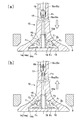
このように、バルブが開閉動作することで、バルブの大径中空部内の冷却材には、図3に示すタンブル流T1,T2が形成されて、大径中空部内全体の冷却材の上層部、中層部、下層部が積極的に攪拌されるため、バルブの熱引き効果(熱伝導性)が著しく改善される。
なお、先行特許文献3では、大径中空部の天井面に小径中空部が連通する構造であるため、バルブの開閉動作の際に、冷却材の一部が連通部を介して大径中空部と小径中空部間で移動し、大径中空部内の冷却材に形成されるタンブル流の勢いがそれだけ弱くなって、大径中空部内の冷却材が十分に攪拌されないおそれがあるのに対し、請求項1では、大径中空部と小径中空部が隔壁で分離されているため、バルブの開閉動作の際に両中空部内の冷却材はそれぞれの中空部内を上下方向にスムーズに移動し、特に、大径中空部では、冷却材に作用する慣性力がタンブル流の形成だけに利用されるので、勢いのあるタンブル流がスムーズに形成されて、冷却材が十分に攪拌され、バルブ傘部における熱引き効果が高くなる。
そして、高温にさらされるバルブ傘表の熱の大半は、大径中空部内の冷却材を介してバルブ傘部に効率よく伝達され、さらにバルブ傘表の熱の一部は、大径中空部の底面まで延びた小径中空部内の冷却材を介してバルブ軸部に直接伝達されるので、バルブ全体の熱引き効果(熱伝導性)が高くなる。
請求項2においては、請求項1に記載の中空ポペットバルブにおいて、前記小径中空部を画成するバルブ軸部の内周面と前記パイプ状の隔壁の内周面を面一に構成した。
(作用)バルブ軸部内からバルブ傘表の裏側まで延びる小径中空部の内周面は、パイプ状の隔壁を含めて軸方向に面一に形成されているので、バルブが開閉動作する際(バルブが上下動作する際)の小径中空部内の冷却材の上下方向への移動がいっそうスムーズになる分、バルブ傘表の熱のバルブ軸部への伝達が活発となる。
請求項3においては、請求項1または2に記載の中空ポペットバルブにおいて、前記バルブ軸端部寄りの小径中空部の内径を前記バルブ傘部寄り小径中空部の内径よりも大きく形成して、前記小径中空部内の軸方向所定位置に円環状の段差部を設けるとともに、前記段差部を越えた位置まで前記冷却材を装填するように構成した。
(作用)バルブが閉弁状態から開弁状態に移行する際(バルブが下降する際)は、小径中空部内の冷却材(液体)が、内径の小さいバルブ傘部寄りの小径中空部から内径の大きいバルブ軸端部寄りの小径中空部に移動する際に、図3(a)に示すように、段差部の下流側で乱流F9が形成されて、小径中空部内の冷却材が攪拌される。
一方、バルブが開弁状態から閉弁状態に移行する際(バルブが上昇する際)は、開弁動作によって小径中空部内を上方にいったん移動した冷却材(液体)が、内径の大きいバルブ軸端部寄りの小径中空部から内径の小さいバルブ傘部寄りの小径中空部に移動する際に、図3(b)に示すように、円環状の段差部の下流側で乱流F10が形成されて、小径中空部内の冷却材が攪拌される。
このように、バルブの開閉動作(上下方向の動作)に伴って、冷却材が小径中空部内を軸方向に移動する際に段差部の近傍に乱流が発生し、これによって小径中空部内の冷却材が攪拌されるので、バルブ軸部における熱引き効果(熱伝導性)がさらに高くなる。
本発明に係る中空ポペットバルブによれば、バルブの開閉動作(上下方向の移動動作)の際に、小径中空部内の冷却材全体が軸方向にスムーズに移動するとともに、大径中空部内の冷却材全体がタンブル流によって積極的に撹拌されて、バルブ傘表の熱の大半が大径中空部内の冷却材を介してバルブ傘部に効率よく伝達されるとともに、バルブ傘表の熱の一部が小径中空部内の冷却材を介してバルブ軸部に直接伝達されるので、バルブ傘部における熱引き効果(熱伝導性)が著しく改善されて、エンジンの性能が向上する。
請求項2によれば、小径中空部内の冷却材の軸方向への移動がいっそうスムーズになる分、小径中空部内の冷却材による熱伝達効率が上がり、バルブの熱引き効果(熱伝導性)がさらに改善される。
請求項3によれば、バルブの開閉動作(上下方向の動作)に伴って、小径中空部内の冷却材も積極的に撹拌されるので、バルブの熱引き効果(熱伝導性)がさらにいっそう改善される。
次に、本発明の実施の形態を実施例に基づいて説明する。
図1~図4は、本発明の第1の実施例である内燃機関用の中空ポペットバルブを示す。
これらの図において、符号10は、真っ直ぐに延びるバルブ軸部12の一端側に、外径が徐々に大きくなるR形状のフィレット部13を介して、バルブ傘部14が一体的に形成された耐熱合金製の中空ポペットバルブで、バルブ傘部14の外周には、テーパ形状のフェース部16が設けられている。
中空ポペットバルブ10の内部には、バルブ傘部14内の大径中空部S1とバルブ軸部12内の小径中空部S2が直交するように配設され、両中空部S1,S2は、円パイプ状の隔壁15によって分離されるとともに、各々の中空部S1,S2には、不活性ガスとともに冷却材19がそれぞれ装填されている。
大径中空部S1の外形は、円形の天井面14b1およびバルブ傘部14の外形に略倣うテーパ形状の外周面14b2を備えた円錐台形状に形成され、小径中空部S2は、バルブ軸部12と同軸の細長い円柱形状に形成されている。
即ち、バルブ軸部12内の小径中空部S2は、該小径中空部S2の大径中空部S2への開口部に固定一体化されてその先端部が大径中空部S2の底面に圧接する円パイプ状の隔壁15によって、大径中空部S2の底面まで延長されている。このため、大径中空部S2は、小径中空部S2の延長された下端部を画成する円パイプ状の隔壁15を取り囲む円環状の空間(テーパ形状の外周面14b2と円パイプ状の隔壁15を内周面とする円環状の略円錐台形状の空間)で構成されている。換言すれば、バルブ軸部12内の小径中空部S2は、大径中空部S2の天井面14b1と底面間に介装された円パイプ状の隔壁15によって、大径中空部S2を貫通して大径中空部S2の底面まで延長されることで、隔壁15回りに画成された大径中空部S2に対し分離されている。
詳しくは、小径中空部S2に相当する孔が形成された軸部12aの一端側に傘部外殻14aを一体的に形成したバルブ中間品である軸一体型シェル(以下、単にシェルという)11と、傘部外殻14aの凹部14bにおける小径中空部S2の開口部に固定一体化された円パイプ状の隔壁15と、傘部外殻14aの凹部14bの開口側内周面14cに接合されてバルブ傘表18aを構成する円盤形状のキャップ18と、シェル11の軸部12aに軸接された軸端部材12bとによって、バルブ傘部14内の大径中空部S1とバルブ軸部12内の小径中空部S2が分離された中空ポペットバルブ10が構成され、中空部S1,S2には、金属ナトリウム等の冷却材19がアルゴンガスなどの不活性ガスとともにそれぞれ装填されている。冷却材19の装填量としては、例えば、中空部S1,S2の容積のほぼ1/2~4/5の量がそれぞれ装填されている。
また、中空部における冷却材の装填量は、一般的には、多いほど熱引き効果(熱伝導性)に優れるが、多くなればなるほど装填量に対する熱引き効果が上がらないし、特に大径中空部内に装填する冷却材については、多過ぎるとタンブル流が形成されにくくなるので、冷却材の装填量は、それぞれの中空部の容積の約1/2から4/5程度が望ましい。
また、大径中空部S1を画成する傘部外殻14aの凹部14b(の円形の底面14b1)に開口する小径中空部S2の開口部には、パイプ状の隔壁15の厚さおよび圧入代を考慮した内径および深さをもつ段差部15aが形成されており、段差部15aに圧入固定された隔壁15の内周面は、バルブ軸部12内の直線状の小径中空部S2の内周面と面一に構成されるとともに、隔壁15の大径中空部S1内への突出量は、大径中空部S1の底面を画成するキャップ18に圧接するように設定されている。
なお、図1における符号2はシリンダヘッド、符号6は燃焼室4から延びる排気通路で、排気通路6の燃焼室4への開口周縁部には、バルブ10のフェース部16が当接できるテーパ面8aを備えた円環状のバルブシート8が設けられている。符号3はシリンダヘッド2に設けられたバルブ挿通孔で、バルブ挿通孔3は、バルブ10の軸部12が摺接する円筒形状のバルブガイド3aで構成されている。符号9は、バルブ10を閉弁方向(図1の上方向)に付勢するバルブスプリング、符号12cは、バルブ軸部12の端部に設けられたコッタ溝である。
また、燃焼室4や排気通路6の高温ガスにさらされる部位である、シェル11およびキャップ18は、耐熱鋼で構成されているのに対し、機械的強度が要求されるものの、シェル11およびキャップ18ほどの耐熱性が要求されない軸端部材12bについては、一般的な鋼材で構成されている。
このように構成された中空ポペットバルブ10では、後で詳しく説明するが、バルブ10が開閉動作する際に、大径中空部S1内の冷却材19は、作用する慣性力によって上下方向に移動する際に、図3(a),(b)に示すように、タンブル流T1,T2が形成されて、冷却材19の上層部,中層部,下層部が積極的に攪拌されることとなって、バルブ10の傘部14の熱引き効果(熱伝導性)が大幅に改善されている。
また、小径中空部S2は、内径d1が比較的大きいバルブ軸端部寄りの小径中空部S21と、内径d2が比較的小さい(d2<d1)バルブ傘部14寄りの小径中空部S22で構成されて、小径中空部S21,S22間には、円環状の段差部17が形成されるとともに、段差部17を越えた位置まで冷却材19が装填されている。
このため、後で詳しく説明するが、小径中空部S2内の冷却材19が、バルブ10が開閉動作する際に作用する慣性力によって上下方向に移動する際に、図3(a),(b)に示すように、段差部17近傍に乱流F9,F10が発生し、冷却材19が攪拌されることとなって、バルブ軸部12における熱引き効果(熱伝導性)が改善されている。
次に、バルブ10が開閉動作する際の中空部S1,S2内の冷却材19の動きを、図2,3に基づいて詳しく説明する。
バルブ10が閉弁状態から開弁状態に移行する際(バルブ10が下降する際)は、図2(a)に示すように、小径中空部S2および大径中空部S1内の冷却材(液体)19には、それぞれ慣性力が上向きに作用するため、それぞれ上方に移動する。
詳しくは、大径中空部S1は、円パイプ状の隔壁15を内周面とし、傘部14の外形に略倣うテーパ形状の外周面14b2を備えた円環状の略円錐台形状に形成されているので、図2(a)に示すように、大径中空部S1中央寄りの冷却材に作用する慣性力(上向き)が大径中空部周辺寄りの冷却材に作用する慣性力よりも大きい。このため、図3(a)に示すように、大径中空部S1中央寄りから天井面14b1に沿って半径方向外側に向かう流れF1が発生する。このとき、大径中空部S1の底面側では、大径中空部S1中央寄りの冷却材が上方に移動することで、大径中空部S1中央寄りの底面側が負圧になって、半径方向外側から内側に向かう流れF3が発生し、これに伴って、大径中空部S1のテーパ形状外周面14b2に沿って下方に向かう流れF2が発生する。
このように、大径中空部S1内の冷却材19には、矢印F1→F2→F3→F1に示すように、バルブの中心軸線Lの周りに外回りのタンブル流T1が形成される。
また、小径中空部S2は直線状に延びているので、冷却材19全体がスムーズに上方に移動し、図3(a)に示すように、冷却材19が上方に移動する際に、段差部17近傍の下流側に乱流F9が発生する。
一方、バルブ10が開弁状態から閉弁状態に移行する際(バルブ10が上昇する際)は、図2(b)に示すように、小径中空部S2および大径中空部S1内の冷却材(液体)19には、それぞれ慣性力が下向きに作用するため、それぞれ下方に移動する。
大径中空部S1内では、大径中空部S1中央寄りの冷却材19に作用する慣性力(下向き)は、図2(b)に示すように、大径中空部S1周辺寄りの冷却材19に作用する慣性力よりも大きい。このため、図3(b)に示すように、大径中空部S1内の冷却材19には、大径中空部S1中央寄りから底面に沿って半径方向外側に向かう流れF6が発生する。このとき、大径中空部S1の天井面14b1側では、大径中空部S1中央寄りの冷却材19が下方に移動することで、大径中空部S1中央寄りの天井面14b1側が負圧になって、半径方向外側から内側に向かう流れF8が発生し、これに伴って、大径中空部S1のテーパ形状外周面14b2に沿って上方に向かう流れF7が発生する。
即ち、大径中空部S1の冷却材19には、矢印F6→F7→F8→F6に示すように、バルブ10の中心軸線Lの周りに内回りのタンブル流T2が形成される。
また、小径中空部S2は直線状に延びているので、バルブ10が開弁状態から閉弁状態に移行する際(バルブ10が上昇する際)にいったん上昇した冷却材19全体がスムーズに下方に移動し、図3(b)に示すように、冷却材19が下方に移動する際に、段差部17近傍の下流側に乱流F10が発生する。
このように、バルブ10の小径中空部S2内の冷却材19は、バルブ10が開閉動作する際に発生する乱流F9,F10によって攪拌され、バルブ10の大径中空部S1内の冷却材19は、バルブ10が開閉動作する際に形成されるタンブル流T1,T2によって、上層部、中層部、下層部が積極的に攪拌されるため、バルブ10の熱引き効果(熱伝導性)が著しく高められている。
特に、高温にさらされるバルブ傘表18aの熱の一部が、バルブ10の開閉動作の際に、大径中空部S1の底面まで延びている小径中空部S2内の冷却材19を介してバルブ軸部12に直接伝達されるので、バルブ10における熱引き効果(熱伝導性)がさらに高められている。
また、小径中空部S内の段差部17は、図1に示すように、バルブガイド3の排気通路6に臨む側の端部3bに略対応する位置に設けられて、内径の大きい軸端部寄り小径中空部S21を軸方向に長く形成することで、バルブ10の耐久性を低下させることなく、バルブ軸部12の冷却材19との接触面積が増えて、バルブ軸部12の熱伝達効率が上がり、小径中空部S21形成壁が薄肉となって、バルブ10も軽量となる。即ち、小径中空部S2内の段差部17は、図1の仮想線に示すように、バルブ10が開弁(下降)しきった状態で、排気通路6内とならない所定位置(バルブ軸部12における薄肉の小径中空部S21形成壁が排気通路6内の熱の影響を受けにくい、バルブ挿通孔3内の所定位置)に設けられている。図1の符号17Xは、バルブ10が開弁(下降)しきった状態での段差部17の位置を示す。
詳しくは、金属の疲労強度は高温になるほど低下するため、常に排気通路6内にあって高熱にさらされる部位である、バルブ軸部12におけるバルブ傘部14寄りの領域は、疲労強度の低下に耐え得る程度の肉厚に形成する必要がある。一方、熱源から離れ、しかも常にバルブガイド3aに摺接する部位である、バルブ軸部12における軸端部寄りの領域は、冷却材19を介して燃焼室4や排気通路6の熱が伝達されるものの、伝達された熱はバルブガイド3aを介して直ちにシリンダヘッド2に放熱されるため、バルブ傘部14寄りの領域ほどの高温となることがない。
即ち、バルブ軸部12における軸端部寄り領域は、バルブ傘部14寄りの領域よりも疲労強度が低下しないため、薄肉に形成(小径中空部S21の内径を大きく形成)しても、強度的(疲労により折損する等の耐久性)には問題がない。
そこで、本実施例では、小径中空部S21の内径を大きく形成して、第1には、小径中空部S2全体の表面積(冷却材19との接触面積)を増やすことで、バルブ軸部12における熱伝達効率が高められている。第2には、小径中空部S2全体の容積を増やすことで、バルブ10の総重量が軽減されている。
また、バルブの軸端部材12bは、シェル11ほどの耐熱性が要求されないため、シェル11の材料よりも耐熱性の低い廉価材を用いることで、バルブ10を安価に提供できる。
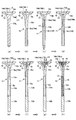
次に、中空ポペットバルブ10の製造工程を、図4に基づいて説明する。
まず、図4(a)に示すように、熱間鍛造により、大径中空部S1に相当する円錐台形状の凹部14bを設けた傘部外殻14aと軸部12aとを一体的に形成したシェル11を成形する。傘部外殻14aの凹部14bの底面14b1は、軸部12a(シェル11の中心軸線L)に対し直交する平面で形成されている。
熱間鍛造工程としては、金型を順次取り替える押し出し鍛造で、耐熱鋼製ブロックからシェル11を製造する押し出し鍛造、またはアップセッタで耐熱鋼製棒材の端部に球状部を据え込んだ後に、金型を用いてシェル11(の傘部外殻14a)を鍛造する据え込み鍛造のいずれであってもよい。なお、熱間鍛造工程において、シェル11の傘部外殻14aと軸部12aとの間には、R形状フィレット部13が形成され、傘部外殻14aの外周面には、テーパ形状フェース部16が形成される。
次に、図4(b)に示すように、傘部外殻14aの凹部14bが上向きとなるようにシェル11を配置し、傘部外殻14aの凹部14b側から、傘部寄り小径中空部S22に相当する円孔14eをドリル加工により穿設する(孔穿設工程)。
次に、図4(c)に示すように、軸部12aの端部側から、軸端部寄り小径中空部S21に相当する円孔14fをドリル加工により穿設する(孔穿設工程)。
次に、図4(d)に示すように、傘部外殻14aの凹部14bにおける円孔14eの開口側に、隔壁15を圧入するための段差部15aを切削加工またはドリル加工により形成する(段差部形成工程)。
次に、図4(e)に示すように、シェル11の軸部12aに軸端部材12bを軸接する(軸端部材軸接工程)。
次に、図4(f)に示すように、傘部外殻14aの凹部14bに開口する円孔14eの段差部15aに、パイプ状の隔壁15を圧入し、必要に応じてロウ付けする(隔壁圧入・ロウ付け工程)。
次に、図4(g)に示すように、円孔14eおよび凹部14bに冷却材(固体)19をそれぞれ所定量充填する(冷却材充填工程)。
次に、図4(h)に示すように、アルゴンガス雰囲気下で、傘部外殻14aの凹部14b(の開口側内周面14c)にキャップ18を配し、パイプ状の隔壁15の先端部にキャップ18を押圧保持した状態で、キャップ18を傘部外殻14aの凹部14bに接合(例えば、抵抗接合)して、大径中空部S1を密閉(大径中空部密閉工程)する。最後に、軸端部にコッタ溝12cを形成する加工を施すことで、バルブ10が完成する。キャップ18の接合は、抵抗接合に代えて、電子ビーム溶接やレーザー溶接等を採用してもよい。
なお、図4(c)に示す孔穿設工程と図4(d)に示す段差部形成工程は、いずれの工程を先に行ってもよい。
図5,6は、本発明の第2の実施例である中空ポペットバルブを示す。
前記した第1の実施例の中空ポペットバルブ10では、シェル11の傘部外殻14aの凹部14bに開口する小径中空部S2の開口部(段差部15a)に固定一体化された円パイプ状の隔壁15が、バルブ軸部12内の小径中空部S2を大径中空部S1の底面(キャップ18の裏面)まで延長するとともに、小径中空部S2を大径中空部S1に対し分離しているが、この第2の実施例の中空ポペットバルブ10Aでは、バルブ傘表18aを構成するキャップ18の裏側に、小径中空部S2’を大径中空部S1の底面(キャップ18の裏面)まで延長するとともに、小径中空部S2’を大径中空部S1に対し分離する、円パイプ状の隔壁15Aが固定一体化されている。
即ち、キャップ18の裏面側には、パイプ状の隔壁15Aが例えばロウ付けや溶接により固定一体化されており、一方、シェル11A(の傘部外殻14aの凹部14b)における小径中空部S2’の開口部には、キャップ18に一体化されたパイプ状の隔壁15Aの先端部を圧入できる段差部15bが形成されている。
そして、パイプ状の隔壁15Aの先端部を傘部外殻14aの凹部14b中央の段差部15bに圧入した状態で、キャップ18がシェル11Aの傘部外殻14aの凹部14b(の開口内周14c)に接合(たとえば、抵抗接合)されることで、大径中空部S1が密閉されている。また、パイプ状の隔壁15Aの先端部が小径中空部S2’の段差部15bに圧入保持されることで、大径中空部S1に対し分離された小径中空部S2’も密閉されている。これらの密閉された大径中空部S1および小径中空部S2’には、金属ナトリウム等の冷却材19がアルゴンガスなどの不活性ガスとともにそれぞれ装填されている。
また、段差部15bに圧入固定された隔壁15Aの内周面は、バルブ軸部12内の直線状の小径中空部S2’の内周面と面一に構成されて、バルブ10Aが開閉動作する際(バルブ10Aが上下動作する際)に、小径中空部S2’内の冷却材19が上下方向にスムーズに移動できる。
また、本実施例のバルブ10Aの小径中空部S2’は、軸方向に一定の内径で構成されて、第1の実施例のバルブ10の小径中空部S2に形成されている段差部17がないため、バルブ10Aが開閉動作する際に、小径中空部S2’内の冷却材19には乱流が発生しない。
その他の構成は、前記した第1の-実施例に係る中空ポペットバルブ10と同一であり、同一の符号を付すことで、その重複した説明は省略する。
次に、中空ポペットバルブ10Aの製造工程を、図6に基づいて説明する。
まず、図6(a)に示すように、熱間鍛造により、円錐台形状の凹部14bを設けた傘部外殻14aとバルブ軸部12とを一体的に形成したシェル11Aを成形する。
次に、図6(b)に示すように、傘部外殻14aの凹部14bが上向きとなるようにシェル11Aを配置し、傘部外殻14aの凹部14b側から小径中空部S2’に相当する円孔14e’をドリル加工により穿設する(孔穿設工程)。
次に、図6(c)に示すように、傘部外殻14aの凹部14bにおける円孔14e’の開口部に、パイプ状の隔壁15Aを圧入するための段差部15bを切削加工またはドリル加工により形成する(隔壁圧入孔形成工程)。
次に、図6(d)に示すように、傘部外殻14aの円孔14e’および凹部14bに冷却材(固体)19をそれぞれ所定量充填する(冷却材充填工程)。冷却材(固体)19は、常温では粘土状であることから、細い棒状にして円孔14e’に挿入できるし、環状にして傘部外殻14aの凹部14b内所定位置に充填することもできる。
次に、図6(e)に示すように、アルゴンガス雰囲気下で、傘部外殻14aの凹部14bにおける円孔14e’の段差部15bにパイプ状の隔壁15Aを圧入しつつ、キャップ18を傘部外殻14aの凹部14bの開口側内周面14cに配し、キャップ18を傘部外殻14aに接合する。最後に軸端部にコッタ溝12cを形成する加工を施すことで、バルブ10Aが完成する。
この第2の実施例のバルブ10Aでは、小径中空部S2’が軸方向に一定の内径で形成されているので、小径中空部S2’に相当する孔を穿設する工程が1工程でよく、さらに軸端部材を軸接する工程も不要となるなど、バルブの製造工程が簡潔となる。
なお、前記した実施例では、大径中空部S1の底面と天井面間に介装されて、小径中空部S2を大径中空部S1の底面(バルブ傘表の裏側)まで延長するとともに、小径中空部S2を大径中空部S1に対し分離するパイプ状の隔壁が、円パイプ状の隔壁15,15Aで構成されているが、軸方向に伸縮できる蛇腹構造のパイプ状の隔壁で構成し、大径中空部S1の底面と天井面間に軸方向に圧縮された形態に介装するようにしてもよい。
10,10A 中空ポペットバルブ
11,11A 傘部外殻と軸部を一体的に形成したバルブ中間部材であるシェル
12 バルブ軸部
12a 軸部
12b 軸端部材
14 バルブ傘部
14a 傘部外殻
14b 傘部外殻の凹部
14b1 大径中空部の円形天井面(凹部の円形底面)
14b2 大径中空部のテーパ形状外周面(凹部のテーパ形状内周面)
15,15A 円パイプ状の隔壁
15a,15b 隔壁圧入用の段差部
17 小径中空部内の段差部
18 キャップ
18a バルブ傘表
19 冷却材
L バルブの中心軸線
S1 円錐台形状の大径中空部
S2 直線状の小径中空部
S2’ 直線状の小径中空部
S21 軸端部寄り小径中空部
S22 傘部寄り小径中空部
T1,T2 タンブル流
F9,F10 乱流
Claims (3)
- 軸部の一端側に傘部を一体的に形成したポペットバルブの傘部から軸部にかけて中空部が形成され、前記中空部に不活性ガスとともに冷却材が装填された中空ポペットバルブにおいて、
前記バルブ傘部内には、該傘部の外形に略倣うテーパ形状の外周面を備えた略円錐台形状の大径中空部が設けられ、前記バルブ軸部内には、前記大径中空部の天井面に対し略直交して連通する直線状の小径中空部が設けられ、
前記大径中空部の底面と天井面間に、前記小径中空部を大径中空部の底面(バルブ傘表の裏側)まで延長して、該小径中空部を前記大径中空部に対し分離するパイプ状の隔壁が介装されるとともに、分離された両中空部には、不活性ガスとともに冷却材がそれぞれ装填されて、前記バルブが軸方向に往復動作する際に、前記大径中空部内の冷却材にバルブの中心軸線周りに内回りのタンブル流が形成されることを特徴とする中空ポペットバルブ。 - 前記小径中空部を画成するバルブ軸部の内周面と前記パイプ状の隔壁の内周面が面一に構成されたことを特徴とする請求項1に記載の中空ポペットバルブ。
- 前記バルブ軸端部寄りの小径中空部の内径が前記バルブ傘部寄り小径中空部の内径よりも大きく形成されて、前記小径中空部内の軸方向所定位置に円環状の段差部が設けられるとともに、前記段差部を越えた位置まで前記冷却材が装填されたことを特徴とする請求項1または2に記載の中空ポペットバルブ。
Priority Applications (2)
| Application Number | Priority Date | Filing Date | Title |
|---|---|---|---|
| PCT/JP2013/059529 WO2014155667A1 (ja) | 2013-03-29 | 2013-03-29 | 中空ポペットバルブ |
| JP2015507869A JP6063558B2 (ja) | 2013-03-29 | 2013-03-29 | 中空ポペットバルブ |
Applications Claiming Priority (1)
| Application Number | Priority Date | Filing Date | Title |
|---|---|---|---|
| PCT/JP2013/059529 WO2014155667A1 (ja) | 2013-03-29 | 2013-03-29 | 中空ポペットバルブ |
Publications (1)
| Publication Number | Publication Date |
|---|---|
| WO2014155667A1 true WO2014155667A1 (ja) | 2014-10-02 |
Family
ID=51622730
Family Applications (1)
| Application Number | Title | Priority Date | Filing Date |
|---|---|---|---|
| PCT/JP2013/059529 WO2014155667A1 (ja) | 2013-03-29 | 2013-03-29 | 中空ポペットバルブ |
Country Status (2)
| Country | Link |
|---|---|
| JP (1) | JP6063558B2 (ja) |
| WO (1) | WO2014155667A1 (ja) |
Cited By (4)
| Publication number | Priority date | Publication date | Assignee | Title |
|---|---|---|---|---|
| US11300018B2 (en) | 2018-03-20 | 2022-04-12 | Nittan Valve Co., Ltd. | Hollow exhaust poppet valve |
| CN115003899A (zh) * | 2020-07-14 | 2022-09-02 | 富士乌兹克斯株式会社 | 伞中空发动机气门的冷却材料填充装置以及冷却材料的填充方法 |
| US11536167B2 (en) | 2018-11-12 | 2022-12-27 | Nittan Valve Co., Ltd. | Method for manufacturing engine poppet valve |
| US11850690B2 (en) | 2020-03-30 | 2023-12-26 | Nittan Corporation | Method for manufacturing engine poppet valve |
Citations (6)
| Publication number | Priority date | Publication date | Assignee | Title |
|---|---|---|---|---|
| JPS6262071A (ja) * | 1985-09-06 | 1987-03-18 | Ishikawajima Harima Heavy Ind Co Ltd | ポペツト形弁の温度制御装置 |
| JP2002511120A (ja) * | 1997-02-14 | 2002-04-09 | マール・ヨット ワイツマン・プレウコ ゲーエムベーハー | ガス交換バルブおよび内燃エンジンの燃焼室内の圧力を測定するための方法 |
| JP2004301124A (ja) * | 2003-03-28 | 2004-10-28 | Eaton Corp | エンジン用の軽量複合ポペット弁 |
| JP2007526419A (ja) * | 2004-03-03 | 2007-09-13 | マーレ ヴェンティルトリープ ゲゼルシャフト ミット ベシュレンクテル ハフツング | 内燃機関のガス交換弁 |
| DE102006061128A1 (de) * | 2006-12-22 | 2008-06-26 | Mahle International Gmbh | Gaswechselventil eines Verbrennungsmotors |
| JP2010106842A (ja) * | 2008-10-31 | 2010-05-13 | Mahle Internatl Gmbh | 高温のガスに曝される弁体のガス封止部の構造 |
-
2013
- 2013-03-29 JP JP2015507869A patent/JP6063558B2/ja not_active Expired - Fee Related
- 2013-03-29 WO PCT/JP2013/059529 patent/WO2014155667A1/ja active Application Filing
Patent Citations (6)
| Publication number | Priority date | Publication date | Assignee | Title |
|---|---|---|---|---|
| JPS6262071A (ja) * | 1985-09-06 | 1987-03-18 | Ishikawajima Harima Heavy Ind Co Ltd | ポペツト形弁の温度制御装置 |
| JP2002511120A (ja) * | 1997-02-14 | 2002-04-09 | マール・ヨット ワイツマン・プレウコ ゲーエムベーハー | ガス交換バルブおよび内燃エンジンの燃焼室内の圧力を測定するための方法 |
| JP2004301124A (ja) * | 2003-03-28 | 2004-10-28 | Eaton Corp | エンジン用の軽量複合ポペット弁 |
| JP2007526419A (ja) * | 2004-03-03 | 2007-09-13 | マーレ ヴェンティルトリープ ゲゼルシャフト ミット ベシュレンクテル ハフツング | 内燃機関のガス交換弁 |
| DE102006061128A1 (de) * | 2006-12-22 | 2008-06-26 | Mahle International Gmbh | Gaswechselventil eines Verbrennungsmotors |
| JP2010106842A (ja) * | 2008-10-31 | 2010-05-13 | Mahle Internatl Gmbh | 高温のガスに曝される弁体のガス封止部の構造 |
Cited By (5)
| Publication number | Priority date | Publication date | Assignee | Title |
|---|---|---|---|---|
| US11300018B2 (en) | 2018-03-20 | 2022-04-12 | Nittan Valve Co., Ltd. | Hollow exhaust poppet valve |
| US11536167B2 (en) | 2018-11-12 | 2022-12-27 | Nittan Valve Co., Ltd. | Method for manufacturing engine poppet valve |
| US11850690B2 (en) | 2020-03-30 | 2023-12-26 | Nittan Corporation | Method for manufacturing engine poppet valve |
| CN115003899A (zh) * | 2020-07-14 | 2022-09-02 | 富士乌兹克斯株式会社 | 伞中空发动机气门的冷却材料填充装置以及冷却材料的填充方法 |
| CN115003899B (zh) * | 2020-07-14 | 2024-03-08 | 富士乌兹克斯株式会社 | 伞中空发动机气门的冷却材料填充装置以及冷却材料的填充方法 |
Also Published As
| Publication number | Publication date |
|---|---|
| JP6063558B2 (ja) | 2017-01-18 |
| JPWO2014155667A1 (ja) | 2017-02-16 |
Similar Documents
| Publication | Publication Date | Title |
|---|---|---|
| JP6072053B2 (ja) | 中空ポペットバルブ | |
| TWI638092B (zh) | 中空提動閥及中空提動閥之隔熱效果與導熱效果之相對值的調整方法 | |
| JP6088641B2 (ja) | 中空ポペットバルブ | |
| JP6163212B2 (ja) | 中空ポペットバルブの製造方法 | |
| JP6063558B2 (ja) | 中空ポペットバルブ | |
| JP6033402B2 (ja) | 中空ポペットバルブ | |
| JP6029742B2 (ja) | 中空ポペットバルブ | |
| JP6251177B2 (ja) | 中空ポペットバルブ | |
| JP6131318B2 (ja) | 中空ポペットバルブ | |
| WO2015170384A1 (ja) | 中空ポペットバルブ |
Legal Events
| Date | Code | Title | Description |
|---|---|---|---|
| 121 | Ep: the epo has been informed by wipo that ep was designated in this application |
Ref document number: 13880004 Country of ref document: EP Kind code of ref document: A1 |
|
| ENP | Entry into the national phase |
Ref document number: 2015507869 Country of ref document: JP Kind code of ref document: A |
|
| NENP | Non-entry into the national phase |
Ref country code: DE |
|
| 122 | Ep: pct application non-entry in european phase |
Ref document number: 13880004 Country of ref document: EP Kind code of ref document: A1 |