EP1460733A2 - Adaptateur à un rail conducteur - Google Patents
Adaptateur à un rail conducteur Download PDFInfo
- Publication number
- EP1460733A2 EP1460733A2 EP04006280A EP04006280A EP1460733A2 EP 1460733 A2 EP1460733 A2 EP 1460733A2 EP 04006280 A EP04006280 A EP 04006280A EP 04006280 A EP04006280 A EP 04006280A EP 1460733 A2 EP1460733 A2 EP 1460733A2
- Authority
- EP
- European Patent Office
- Prior art keywords
- housing
- switching shaft
- housing shell
- shell part
- latching
- Prior art date
- Legal status (The legal status is an assumption and is not a legal conclusion. Google has not performed a legal analysis and makes no representation as to the accuracy of the status listed.)
- Granted
Links
Images


Classifications
-
- H—ELECTRICITY
- H01—ELECTRIC ELEMENTS
- H01R—ELECTRICALLY-CONDUCTIVE CONNECTIONS; STRUCTURAL ASSOCIATIONS OF A PLURALITY OF MUTUALLY-INSULATED ELECTRICAL CONNECTING ELEMENTS; COUPLING DEVICES; CURRENT COLLECTORS
- H01R25/00—Coupling parts adapted for simultaneous co-operation with two or more identical counterparts, e.g. for distributing energy to two or more circuits
- H01R25/14—Rails or bus-bars constructed so that the counterparts can be connected thereto at any point along their length
-
- H—ELECTRICITY
- H01—ELECTRIC ELEMENTS
- H01R—ELECTRICALLY-CONDUCTIVE CONNECTIONS; STRUCTURAL ASSOCIATIONS OF A PLURALITY OF MUTUALLY-INSULATED ELECTRICAL CONNECTING ELEMENTS; COUPLING DEVICES; CURRENT COLLECTORS
- H01R13/00—Details of coupling devices of the kinds covered by groups H01R12/70 or H01R24/00 - H01R33/00
- H01R13/46—Bases; Cases
- H01R13/502—Bases; Cases composed of different pieces
- H01R13/506—Bases; Cases composed of different pieces assembled by snap action of the parts
-
- F—MECHANICAL ENGINEERING; LIGHTING; HEATING; WEAPONS; BLASTING
- F21—LIGHTING
- F21V—FUNCTIONAL FEATURES OR DETAILS OF LIGHTING DEVICES OR SYSTEMS THEREOF; STRUCTURAL COMBINATIONS OF LIGHTING DEVICES WITH OTHER ARTICLES, NOT OTHERWISE PROVIDED FOR
- F21V21/00—Supporting, suspending, or attaching arrangements for lighting devices; Hand grips
- F21V21/34—Supporting elements displaceable along a guiding element
- F21V21/35—Supporting elements displaceable along a guiding element with direct electrical contact between the supporting element and electric conductors running along the guiding element
-
- H—ELECTRICITY
- H01—ELECTRIC ELEMENTS
- H01R—ELECTRICALLY-CONDUCTIVE CONNECTIONS; STRUCTURAL ASSOCIATIONS OF A PLURALITY OF MUTUALLY-INSULATED ELECTRICAL CONNECTING ELEMENTS; COUPLING DEVICES; CURRENT COLLECTORS
- H01R13/00—Details of coupling devices of the kinds covered by groups H01R12/70 or H01R24/00 - H01R33/00
- H01R13/46—Bases; Cases
- H01R13/50—Bases; Cases formed as an integral body
- H01R13/501—Bases; Cases formed as an integral body comprising an integral hinge or a frangible part
-
- H—ELECTRICITY
- H01—ELECTRIC ELEMENTS
- H01R—ELECTRICALLY-CONDUCTIVE CONNECTIONS; STRUCTURAL ASSOCIATIONS OF A PLURALITY OF MUTUALLY-INSULATED ELECTRICAL CONNECTING ELEMENTS; COUPLING DEVICES; CURRENT COLLECTORS
- H01R31/00—Coupling parts supported only by co-operation with counterpart
- H01R31/06—Intermediate parts for linking two coupling parts, e.g. adapter
-
- Y—GENERAL TAGGING OF NEW TECHNOLOGICAL DEVELOPMENTS; GENERAL TAGGING OF CROSS-SECTIONAL TECHNOLOGIES SPANNING OVER SEVERAL SECTIONS OF THE IPC; TECHNICAL SUBJECTS COVERED BY FORMER USPC CROSS-REFERENCE ART COLLECTIONS [XRACs] AND DIGESTS
- Y10—TECHNICAL SUBJECTS COVERED BY FORMER USPC
- Y10S—TECHNICAL SUBJECTS COVERED BY FORMER USPC CROSS-REFERENCE ART COLLECTIONS [XRACs] AND DIGESTS
- Y10S439/00—Electrical connectors
- Y10S439/901—Connector hood or shell
- Y10S439/904—Multipart shell
- Y10S439/906—Longitudinally divided
Definitions
- the invention relates to a device for the at least indirect connection of a lamp with a busbar according to the preamble of claim 1.
- a device for the at least indirect connection of a luminaire to a busbar is commonly referred to as a busbar adapter.
- a busbar In a busbar, a plurality of lights, axially displaceable, can be fastened in a simple manner.
- the known busbar adapter consists of a variety of items and requires a complex assembly.
- the housing consists of three housing shell parts, which are held together by means of conventional threaded screws.
- the first shift shaft is pivotable through a 90 ° angle and has a pair of retaining tabs and a neutral contact tongue.
- the second switching shaft is pivotable through 180 ° and in particular has a phase conductor contact tongue.
- a locking member G is arranged, which in the form of a mutual control ensures that no incorrect operation occurs.
- the object of the invention is to develop the known from DE 28 10 681 A1 busbar adapter according to the preamble of claim 1 such that a simpler installation is possible.
- the invention solves this problem with the features of claim 1, in particular with those of the characterizing part and is accordingly characterized in that at least one first housing shell part a locking member is arranged, which cooperates with the switching shaft and / or with a second housing shell part.
- the principle of the invention is thus essentially to provide locking members, which may be formed, for example, in the manner of clip elements and exercise a holding function.
- latching members of the first kind which are arranged on a first housing shell part and which cooperate with corresponding retaining surfaces on another housing shell part.
- latching members of the first kind which are arranged on a first housing shell part and which cooperate with corresponding retaining surfaces on another housing shell part.
- the locking members may be formed in the manner of snap connection elements that can automatically snap in an automatic movement of a housing shell part relative to the other.
- the locking members may also be provided to cooperate with the shift shaft.
- the busbar adapter which almost completely corresponds both to its outer structure, as well as in terms of its internal parts and its functions from the busbar adapter known from DE 28 10 681 A1, has a first and a second switching shaft, which is pivotable in the housing are stored.
- the first and the second switching shaft for their assembly are only loosely, successively, inserted into the first housing shell. Subsequently, further elements, in particular the locking member, are introduced into the interior of the housing. Finally, connecting conductors that are used for electrical connection with a luminaire are fastened to the corresponding connection terminals. Since the two switching shafts were only loosely inserted, such an attachment designed partially tedious.
- a precisely defined locking seat for the first and / or for the second control shaft by providing at least one locking member.
- a well-defined detent position can be displayed to the user by a sound, which occurs when clips, and then when the proper detent position is reached.
- the switching shaft located in the locking position may preferably be pivotable, so that the locking members in no way affect the switching shaft in their switching function.
- the locking position optionally also allows a z.
- the locking seat for the switching shaft cooperates with an axial securing for the switching shaft, so that a connection conductor for a light can be easily connected by making a connector by moving the free end of the connecting conductor in the axial direction with a corresponding terminal contact in the switching shaft.
- a first type of locking member is provided, which cooperates with the shift shaft and a second type of locking member provided, which cooperates with the second housing shell part.
- the assembly is further facilitated.
- the locking member is integrally formed cohesively to the housing shell part.
- the latching element can be injection-molded, so that the production outlay of the latching element is minimized.
- the locking member is resilient. This allows a particularly simple construction, which can be dispensed with additional items.
- the locking member is designed as a spring tongue.
- the spring tongue protrudes freely from a bottom wall of the housing shell part. Due to the axial length of the spring tongue, the desired elasticity of the locking member can be readily adjusted.
- the housing consists essentially of two housing halves, which are connected to each other via a film hinge.
- the one-piece housing can also be mechanically transferred by pivoting the two housing halves relative to each other in the closed, assembled state.
- a plurality of locking members on the first housing half cooperate with corresponding retaining surfaces on the second housing half.
- the retaining surfaces are arranged in the region of openings in the wall of the housing shell part. This allows a particularly efficient and material-saving accommodation of retaining surfaces and locking members. In addition, in this way, the locking members are accessible from outside even in the assembled state of the housing and can be attacked for example for opening the housing with a loose tool.
- a locking member of the first kind engages around the switching shaft, in particular an outer circumferential surface of the switching shaft, at least partially. This embodiment of the invention ensures a particularly simple securing of the switching shaft to the housing shell part.
- At least one pair of locking members of the first type is provided, which clasps the shift shaft.
- an optimal power distribution is achieved in a particularly simple manner.
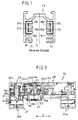
- the apparatus designated in the figures in its entirety by 10 serves to connect a luminaire, not shown, to a conventional busbar, designated by the reference numeral 11 in FIG.
- a bus bar is on the building side, in particular on the ceiling side, mounted and serves to accommodate a
- the device 10 corresponds in its external dimensions, and of its structural internal structure forth, at least as regards their functionalities, largely described in DE 28 10 681 A1, there as a busbar adapter designated device of the applicant.
- the busbar 11 has an insertion opening 13, which serves to receive the insertion section 12 of the device 10.
- the device 10 is inserted so far into the insertion opening 13, until a stop surface 14 of the device 10 comes to rest on the underside 15 of the busbar 11 or at least in their area.
- a coding groove 16 is arranged on the busbar 11, in the coding 17, which are mounted in the region of the stop surface 14 on the device 10, can penetrate.
- the busbar 11 has a multiplicity of channels 18a, 18b, 18c, 18d, 18e, 18f, which are designed as holders (for example, 18a, 18f) or as contact channels. In the grooves 18b, 18c, 18d, 18e ladder rails are arranged.
- the conductor rail 19 is designed as a neutral conductor rail, and the remaining three conductor rails are phase conductor rails 20a, 20b, 20c, as is common in the prior art.
- the device 10 is used for electrical contacting and usually also for mechanical attachment of a lamp, not shown in the figures on the busbar 11.
- a Screw connection made in the mounting portion 37 of the device 10, for example by screwing or bracing a fastening element, not shown, of the lamp. It is also known to attach to the attachment portion 37 of the device 10 separate fastening devices, in the manner of holders.
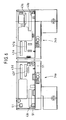
- first switching shaft 21 (FIG. 3) and a second switching shaft 22 is arranged.
- Each of the two switching shafts 21, 22 is pivotable about its own pivot axis 23.
- the first switching shaft 21 is pivotable about 90 °, and for this purpose has an out of the outer dimensions of a housing 38 also projecting actuating lever 34 which can be manually operated.
- second switching shaft 22 which is pivotable substantially over a circumferential angular range of 180 °, are provided at the bottom with respect to FIG. 3 end handle 25 in the manner of an external toothing, which allow easy manual attack.
- a locking member 39 is shown in FIG. 3 approximately centrally between the two switching shafts 21, 22 and provides for mutual control.
- the first shift shaft 21 has a neutral contact tongue 26, which projects radially outward with respect to the pivot axis 23 of the shift shaft 21.
- two of the mechanical support serving retaining tongues 27a, 27b are provided.
- the first shift shaft 21 has a head portion 29, a middle portion 30 and a foot portion 31. Head and middle section have a substantially identical outer diameter, wherein the outer diameter of the foot portion 30, however, greatly increased. Overall, the first shift shaft 21 is formed as a hollow body and has central openings 40a, 40b.
- the neutral contact tongue 26 is part of a contact carrier 32, which is formed for example as a stamped part of a copper sheet by bending. At its lower end with respect to FIG. 11, the contact carrier 32 has a tongue 33, which serves to connect to a tab sleeve of a light-side, not shown connecting conductor.
- the second switching shaft 22 has a phase conductor contact tongue 28, which projects in a similar manner as in the switching shaft 21 from the pivot axis 23 radially outwardly away.
- the phase conductor contact tongue 28 is a component of a contact carrier 32, which may also be formed as a copper sheet stamped part.
- the contact carrier 32 of the second switching shaft 22 is located in a chamber-like space 41 and has a mounting portion 42, by means of which the contact carrier 32 is fixed.
- a tongue 33 points upward with respect to FIG. 13, and is aligned substantially along the pivot axis 23.
- the tongue 33 is used for electrical connection with a not shown tabs sleeve of a connecting conductor, not shown.
- the second switching shaft 22 can be divided into a head portion 29 and a central portion 30, which have a significantly smaller outer diameter compared to a foot portion 31.
- the first shift shaft 21 is equally as the shift shaft 22 prior to insertion of the insertion section 12 into the insertion opening 13 in a non-use position.
- the retaining tongues 27a, 27b and the neutral contact tongue 26 as well as the contact tongue 27 and the phase conductor contact tongue 28 of the second control shaft 22 are arranged in this position within the housing 38.
- the first switching shaft 21 can be pivoted about its longitudinal axis 23 by operating the lever 24 by about 90 °, wherein the retaining tongues 27a, 27b and the neutral contact tongue 26 through slots provided for this purpose 43a, 43b 43c can emerge from the housing 38.
- the retaining tongues 27a, 27b penetrate into the corresponding holders 18a, 18f, whereas the neutral contact tongue 26 enters the correspondingly provided neutral contact channel 18e for contacting the neutral conductor rail 19.
- the first shift shaft 21 thus reaches its use position.
- the axially displaceable with respect to FIG. 3 along the double arrow y locking member 39 can be moved due to an outer circumferential groove, not shown on the first switching shaft 21 now in a position in which it allows pivoting of the second switching shaft 22 from its non-use position out. It should be noted that in the inoperative position located first shift shaft 21, a pivoting of the second shift shaft 22 from its rest position is not possible because the locking member 39 ensures a blocking of this movement.
- the blocking member may be formed, for example, as described in DE 28 10 681 A1.
- the second shift shaft 22 When the second shift shaft 22 is shifted from its non-use position to a use position, three different usage positions can be achieved. Depending on whether starting from the non-use position according to FIG. 3 of the second control shaft 22 pivoting by 90 ° counterclockwise or clockwise, a first or a second use position is reached, in which the phase conductor contact tongue 28 either from an upper housing slot 43d or emerges from a lower housing slot 43e. The retaining tongue 27 of the second switching shaft 22 accordingly emerges through the respective other housing slot 43e, 43d.
- an axial displacement of the second switching shaft 22 with respect to FIG. 3 downwards be performed so that, a subsequent further pivoting provided by 90 °, the phase conductor contact tongue 28 can escape through the housing slot 43 f.
- the retaining tongue 27 exits through the housing slot 43g.
- the housing 38 consists of two housing halves 34a, 34b, which are designed as half shells.
- the two housing halves 34a, 34b are connected to each other via a film hinge 44 and thus form a single component.
- the two housing halves 34a, 34b have a bottom wall 35 from which project a plurality of elements.
- side wall portions 46 a, 46 b, 46 c are provided, which form a pivot bearing for the first shift shaft 21.
- corresponding wall portions 46d, 46e, 46f are provided, which form a pivot bearing for the second switching shaft 22.
- the peculiarity of the present device 10 is that a plurality of latching members 36a, 36b, 36c, 36d, 36e, 36f, 36g, 36h is provided.
- Each latching member 36a, 36b, 36c, 36d, 36e, 36f, 36g, 36h is formed as a spring tongue element.
- the latching element 36c will be described by way of example with reference to FIG. 8: it is connected to the bottom wall 35 of the housing half 34b via a fastening region 47.
- An axially elongate portion 48 terminates in a hooked end 49 having a hook surface 50.
- the end 49 is slightly deflectable about a perpendicular to the paper plane, extending substantially through the mounting portion 47 pivot axis.
- an opening 51 is arranged, which provides a holding surface 52. If the two housing halves 34a, 34b are pivoted relative to one another about the pivot axis 45 toward one another, the hook end 49 having a control surface 54 passes through the opening 51 until, after snapping back, the hook surface 50 lies on the holding surface 52 and the two housing halves 34a, 34b are permanently secured together.
- locking member 36a, 36b, 36c For attachment of the two housing halves 34a, 34b to each other, in addition to the locking member 36c also attached in the edge region 53 of the housing 38 locking member 36b and locking member 36a is provided, the latter being disposed on the film hinge facing the edge region 53.
- three locking members 36a, 36b, 36c which are formed substantially identical, arranged to lock the two housing halves 34a, 34b with each other.
- corresponding openings 51 are provided for the locking members 36a and 36b.
- the locking members 36a, 36b, 36c are referred to as locking members of the second kind.
- locking devices 36d, 36e, 36f, 36g of the first type and a latching element 36h of the third type are also provided on the device 10.
- the locking member 36h third type is similar to the locking members 36a, 36b, 36c and serves to define the locking member 39. This will not be further described here.
- the locking members of the first type are used to attach the switching shafts 21, 22nd
- a pair of opposing detent members 36f and 36g are provided, which engage the outer circumferential surface of the middle portion 30 of the second shift shaft 22.
- the locking members 36f, 36g are, as partially apparent from Fig. 7, formed substantially like a clasp and clasp in the latching position shown in FIG. 3 befind Anlagen second shift shaft whose central portion 30th
- a latching member 36 d To secure the first shift shaft 21 on the housing 38 is a latching member 36 d, and with respect to FIG. 3 axially offset down, a second latching member 36 e is provided.
- the two locking members 36d and 36e embrace the first shift shaft 21 on its outer circumferential surface equally clasp-like, but axially offset.
- the locking member 36d engages around the head portion 29 and the locking member 37e, the central portion 30 of the first shift shaft 21st
- the latching members 36d, 36e, 36f, 36g bend momentarily outward, since their projected minimum distance m 1 or m 2 is smaller , as the outer diameter of the corresponding portion 29, 30 of the corresponding switching shaft 21, 22.
- an automated transport can be carried out as part of an automated assembly.
- the locking members of the first type are designed so that a secure locking seat for the switching shaft 21, 22 is achieved.
- the reaching of the locking seat can be signaled by an acoustic sound, for example by a clip, the user.
- the locking members of the first type are also designed so that they do not affect a pivotal movement of the first and second switching shaft 21, 22. On the contrary, they form a pivot bearing for the respective selector shaft 21, 22 with.
Applications Claiming Priority (2)
| Application Number | Priority Date | Filing Date | Title |
|---|---|---|---|
| DE10312066 | 2003-03-18 | ||
| DE10312066A DE10312066B4 (de) | 2003-03-18 | 2003-03-18 | Stromschienen-Adapter |
Publications (3)
| Publication Number | Publication Date |
|---|---|
| EP1460733A2 true EP1460733A2 (fr) | 2004-09-22 |
| EP1460733A3 EP1460733A3 (fr) | 2005-09-21 |
| EP1460733B1 EP1460733B1 (fr) | 2010-03-10 |
Family
ID=32797969
Family Applications (1)
| Application Number | Title | Priority Date | Filing Date |
|---|---|---|---|
| EP04006280A Expired - Lifetime EP1460733B1 (fr) | 2003-03-18 | 2004-03-17 | Adaptateur à un rail conducteur |
Country Status (6)
| Country | Link |
|---|---|
| US (1) | US7086875B2 (fr) |
| EP (1) | EP1460733B1 (fr) |
| JP (2) | JP2004281410A (fr) |
| AT (1) | ATE460758T1 (fr) |
| DE (2) | DE10312066B4 (fr) |
| ES (1) | ES2341105T3 (fr) |
Cited By (1)
| Publication number | Priority date | Publication date | Assignee | Title |
|---|---|---|---|---|
| EP2779320A1 (fr) * | 2013-03-12 | 2014-09-17 | MCQ TECH GmbH | Connecteur à fiches pour un câble de données et/ou de télécommunications multi-brins |
Families Citing this family (12)
| Publication number | Priority date | Publication date | Assignee | Title |
|---|---|---|---|---|
| DE102005019632A1 (de) * | 2005-04-26 | 2006-11-09 | Erco Leuchten Gmbh | Leuchte, Betriebsgerät, Stromschiene, Schaltungsanordnung und Stromschienen-Adapter |
| US7654834B1 (en) * | 2008-05-05 | 2010-02-02 | Genlyte Thomas Group, Llc | Track lighting assembly |
| US8992238B2 (en) | 2010-07-12 | 2015-03-31 | Ferno-Washington, Inc. | Mounting system having a mounting plate with mounting studs and electrical contacts |
| US8899999B2 (en) | 2012-09-24 | 2014-12-02 | Abl Ip Holding Llc | Track adapter and lighting fixture |
| JP6247706B2 (ja) | 2013-02-11 | 2017-12-13 | ファーノ−ワシントン・インコーポレーテッド | 機器取り付けシステム |
| US10307313B2 (en) | 2013-02-11 | 2019-06-04 | Ferno-Washington, Inc. | Equipment mounting system |
| US9944217B2 (en) | 2013-02-11 | 2018-04-17 | Ferno-Washington, Inc. | Equipment mounting system |
| US10912360B2 (en) | 2014-02-11 | 2021-02-09 | Ferno-Washington, Inc. | Magnetic pouch attachment mechanism with crash stable locking teeth |
| US11083265B2 (en) | 2014-02-11 | 2021-08-10 | Ferno-Washington, Inc. | Magnetic pouch attachment mechanism with crash stable locking teeth |
| US10398203B2 (en) | 2014-02-11 | 2019-09-03 | Ferno-Washington, Inc. | Crash-ready, portable, compartmentalization device |
| EP3450259B1 (fr) | 2014-07-18 | 2020-12-16 | Ferno-Washington, Inc. | Mécanisme de fixation magnétique de pochette à dents de verrouillage stable à l'écrasement |
| USD776514S1 (en) | 2015-04-21 | 2017-01-17 | Ferno-Washington, Inc. | Mounting adaptor for attachment to a track |
Citations (2)
| Publication number | Priority date | Publication date | Assignee | Title |
|---|---|---|---|---|
| DE2810681A1 (de) * | 1978-03-11 | 1979-09-20 | Erco Leuchten | Adapter fuer ein- oder mehrphasige stromentnahmeschienen |
| DE20116392U1 (de) * | 2001-10-05 | 2001-12-20 | Briloner Leuchten Gmbh | Stromschienensystem für Leuchten |
Family Cites Families (12)
| Publication number | Priority date | Publication date | Assignee | Title |
|---|---|---|---|---|
| US3519978A (en) * | 1967-09-15 | 1970-07-07 | Essex International Inc | Connector construction |
| CH497658A (de) | 1969-04-15 | 1970-10-15 | Escher Wyss Ag | Hydraulischer Kreiskolbenantrieb zu Drehschieber für Rohrleitungen |
| US4210380A (en) * | 1978-11-08 | 1980-07-01 | Western Electric Company, Inc. | Cable connector housing having strain relief system |
| SE8306211L (sv) * | 1983-11-11 | 1985-05-12 | Skf Ab | Rullningslagerhallare |
| US4702975A (en) * | 1987-01-12 | 1987-10-27 | Roy Fields | Spare battery holder for a battery-operated device |
| NL9200469A (nl) * | 1992-03-13 | 1993-10-01 | Lumiance Bv | Aftakorgaan. |
| US5432689A (en) * | 1993-01-13 | 1995-07-11 | Streamlight, Inc. | Flashlight and recharging system therefor |
| US5460545A (en) * | 1993-10-28 | 1995-10-24 | The Siemon Company | Patch connector |
| US5879203A (en) * | 1997-01-27 | 1999-03-09 | Micron Industries Corporation | Fuse holder clip |
| US6074238A (en) * | 1998-05-15 | 2000-06-13 | Molex Incorporated | Electrical tap connector with spreader means |
| JP4813644B2 (ja) * | 2000-08-22 | 2011-11-09 | 旭電機化成株式会社 | 電池アダプタケース |
| CN1326290C (zh) * | 2002-01-18 | 2007-07-11 | 奥创利公司 | 转接插头设计及其使用方法 |
-
2003
- 2003-03-18 DE DE10312066A patent/DE10312066B4/de not_active Expired - Fee Related
-
2004
- 2004-03-17 US US10/802,695 patent/US7086875B2/en not_active Expired - Fee Related
- 2004-03-17 AT AT04006280T patent/ATE460758T1/de not_active IP Right Cessation
- 2004-03-17 EP EP04006280A patent/EP1460733B1/fr not_active Expired - Lifetime
- 2004-03-17 DE DE502004010870T patent/DE502004010870D1/de not_active Expired - Lifetime
- 2004-03-17 ES ES04006280T patent/ES2341105T3/es not_active Expired - Lifetime
- 2004-03-18 JP JP2004118386A patent/JP2004281410A/ja not_active Withdrawn
-
2008
- 2008-04-09 JP JP2008101852A patent/JP2008226848A/ja active Pending
Patent Citations (2)
| Publication number | Priority date | Publication date | Assignee | Title |
|---|---|---|---|---|
| DE2810681A1 (de) * | 1978-03-11 | 1979-09-20 | Erco Leuchten | Adapter fuer ein- oder mehrphasige stromentnahmeschienen |
| DE20116392U1 (de) * | 2001-10-05 | 2001-12-20 | Briloner Leuchten Gmbh | Stromschienensystem für Leuchten |
Cited By (2)
| Publication number | Priority date | Publication date | Assignee | Title |
|---|---|---|---|---|
| EP2779320A1 (fr) * | 2013-03-12 | 2014-09-17 | MCQ TECH GmbH | Connecteur à fiches pour un câble de données et/ou de télécommunications multi-brins |
| US9214761B2 (en) | 2013-03-12 | 2015-12-15 | MCQ TECH GmbH | Plug-in connector having a cable sheath with two parts adjustable in different positions relative to each other |
Also Published As
| Publication number | Publication date |
|---|---|
| DE10312066B4 (de) | 2005-12-29 |
| JP2008226848A (ja) | 2008-09-25 |
| DE10312066A1 (de) | 2004-10-07 |
| US7086875B2 (en) | 2006-08-08 |
| EP1460733B1 (fr) | 2010-03-10 |
| JP2004281410A (ja) | 2004-10-07 |
| DE502004010870D1 (de) | 2010-04-22 |
| EP1460733A3 (fr) | 2005-09-21 |
| ES2341105T3 (es) | 2010-06-15 |
| US20040253856A1 (en) | 2004-12-16 |
| ATE460758T1 (de) | 2010-03-15 |
Similar Documents
| Publication | Publication Date | Title |
|---|---|---|
| EP1811604B1 (fr) | Barette à bornes électriques | |
| EP1766743B1 (fr) | Systeme a barres omnibus avec unite de montage formee d'une plaque de base et d'elements de fixation | |
| EP1460733B1 (fr) | Adaptateur à un rail conducteur | |
| DE19727048C2 (de) | Steckverbindung | |
| DE102011054563B3 (de) | Steckverbinder | |
| EP0959529A2 (fr) | Unité de connection électrique | |
| DE4017453C2 (fr) | ||
| DE4336965A1 (de) | Lösbare Kontaktklemme | |
| DE19526248C2 (de) | Steckverbinder | |
| DE102019000410B4 (de) | Leuchte und Adapter für Leuchte | |
| EP1460734A2 (fr) | Adaptateur à un rail conducteur | |
| DE3816909C2 (fr) | ||
| EP1783868B1 (fr) | Broche de contact estampée et courbée | |
| EP1672751B1 (fr) | Douille de lampe | |
| DE19706865C2 (de) | Adapter für Stromschienen | |
| DE102014110230B4 (de) | Steckverbinderanordnung | |
| DE20304394U1 (de) | Stromschienen-Adapter | |
| DE2535879C3 (de) | Steckfassung für elektrische Glassockellampen | |
| EP2583357A1 (fr) | Bloc de jonction | |
| EP1206008B1 (fr) | Connecteur pour connecter des lignes électriques à un appareil électrique, en particulier pour un moteur | |
| EP1445840B1 (fr) | Connecteur Electrique | |
| DE20304393U1 (de) | Stromschienen-Adapter | |
| DE202015101737U1 (de) | Anschlussklemme | |
| DE4311633C2 (de) | In einer Einbauöffnung einer Kfz.-Wandung befestigbare Lampenfassung aus Kunststoff | |
| DE19535206C1 (de) | Lampenfassung mit Schutzkappe und Zugentlastung |
Legal Events
| Date | Code | Title | Description |
|---|---|---|---|
| PUAI | Public reference made under article 153(3) epc to a published international application that has entered the european phase |
Free format text: ORIGINAL CODE: 0009012 |
|
| AK | Designated contracting states |
Kind code of ref document: A2 Designated state(s): AT BE BG CH CY CZ DE DK EE ES FI FR GB GR HU IE IT LI LU MC NL PL PT RO SE SI SK TR |
|
| AX | Request for extension of the european patent |
Extension state: AL LT LV MK |
|
| PUAL | Search report despatched |
Free format text: ORIGINAL CODE: 0009013 |
|
| AK | Designated contracting states |
Kind code of ref document: A3 Designated state(s): AT BE BG CH CY CZ DE DK EE ES FI FR GB GR HU IE IT LI LU MC NL PL PT RO SE SI SK TR |
|
| AX | Request for extension of the european patent |
Extension state: AL LT LV MK |
|
| RIC1 | Information provided on ipc code assigned before grant |
Ipc: 7H 01R 25/14 A Ipc: 7H 01R 13/506 B |
|
| 17P | Request for examination filed |
Effective date: 20051025 |
|
| AKX | Designation fees paid |
Designated state(s): AT BE BG CH CY CZ DE DK EE ES FI FR GB GR HU IE IT LI LU MC NL PL PT RO SE SI SK TR |
|
| 17Q | First examination report despatched |
Effective date: 20061129 |
|
| RAP1 | Party data changed (applicant data changed or rights of an application transferred) |
Owner name: ERCO GMBH |
|
| GRAP | Despatch of communication of intention to grant a patent |
Free format text: ORIGINAL CODE: EPIDOSNIGR1 |
|
| GRAS | Grant fee paid |
Free format text: ORIGINAL CODE: EPIDOSNIGR3 |
|
| GRAA | (expected) grant |
Free format text: ORIGINAL CODE: 0009210 |
|
| AK | Designated contracting states |
Kind code of ref document: B1 Designated state(s): AT BE BG CH CY CZ DE DK EE ES FI FR GB GR HU IE IT LI LU MC NL PL PT RO SE SI SK TR |
|
| REG | Reference to a national code |
Ref country code: GB Ref legal event code: FG4D Free format text: NOT ENGLISH |
|
| REG | Reference to a national code |
Ref country code: CH Ref legal event code: EP |
|
| REG | Reference to a national code |
Ref country code: IE Ref legal event code: FG4D |
|
| REF | Corresponds to: |
Ref document number: 502004010870 Country of ref document: DE Date of ref document: 20100422 Kind code of ref document: P |
|
| REG | Reference to a national code |
Ref country code: SE Ref legal event code: TRGR |
|
| PGFP | Annual fee paid to national office [announced via postgrant information from national office to epo] |
Ref country code: FR Payment date: 20100331 Year of fee payment: 7 |
|
| REG | Reference to a national code |
Ref country code: NL Ref legal event code: T3 |
|
| REG | Reference to a national code |
Ref country code: ES Ref legal event code: FG2A Ref document number: 2341105 Country of ref document: ES Kind code of ref document: T3 |
|
| PGFP | Annual fee paid to national office [announced via postgrant information from national office to epo] |
Ref country code: ES Payment date: 20100412 Year of fee payment: 7 |
|
| PG25 | Lapsed in a contracting state [announced via postgrant information from national office to epo] |
Ref country code: FI Free format text: LAPSE BECAUSE OF FAILURE TO SUBMIT A TRANSLATION OF THE DESCRIPTION OR TO PAY THE FEE WITHIN THE PRESCRIBED TIME-LIMIT Effective date: 20100310 Ref country code: PL Free format text: LAPSE BECAUSE OF FAILURE TO SUBMIT A TRANSLATION OF THE DESCRIPTION OR TO PAY THE FEE WITHIN THE PRESCRIBED TIME-LIMIT Effective date: 20100310 Ref country code: SI Free format text: LAPSE BECAUSE OF FAILURE TO SUBMIT A TRANSLATION OF THE DESCRIPTION OR TO PAY THE FEE WITHIN THE PRESCRIBED TIME-LIMIT Effective date: 20100310 |
|
| PGFP | Annual fee paid to national office [announced via postgrant information from national office to epo] |
Ref country code: IT Payment date: 20100329 Year of fee payment: 7 Ref country code: NL Payment date: 20100330 Year of fee payment: 7 |
|
| BERE | Be: lapsed |
Owner name: ERCO G.M.B.H. Effective date: 20100331 |
|
| REG | Reference to a national code |
Ref country code: IE Ref legal event code: FD4D |
|
| PG25 | Lapsed in a contracting state [announced via postgrant information from national office to epo] |
Ref country code: EE Free format text: LAPSE BECAUSE OF FAILURE TO SUBMIT A TRANSLATION OF THE DESCRIPTION OR TO PAY THE FEE WITHIN THE PRESCRIBED TIME-LIMIT Effective date: 20100310 Ref country code: GR Free format text: LAPSE BECAUSE OF FAILURE TO SUBMIT A TRANSLATION OF THE DESCRIPTION OR TO PAY THE FEE WITHIN THE PRESCRIBED TIME-LIMIT Effective date: 20100611 Ref country code: MC Free format text: LAPSE BECAUSE OF NON-PAYMENT OF DUE FEES Effective date: 20100331 Ref country code: RO Free format text: LAPSE BECAUSE OF FAILURE TO SUBMIT A TRANSLATION OF THE DESCRIPTION OR TO PAY THE FEE WITHIN THE PRESCRIBED TIME-LIMIT Effective date: 20100310 Ref country code: CY Free format text: LAPSE BECAUSE OF FAILURE TO SUBMIT A TRANSLATION OF THE DESCRIPTION OR TO PAY THE FEE WITHIN THE PRESCRIBED TIME-LIMIT Effective date: 20100310 |
|
| REG | Reference to a national code |
Ref country code: CH Ref legal event code: PL |
|
| PG25 | Lapsed in a contracting state [announced via postgrant information from national office to epo] |
Ref country code: BG Free format text: LAPSE BECAUSE OF FAILURE TO SUBMIT A TRANSLATION OF THE DESCRIPTION OR TO PAY THE FEE WITHIN THE PRESCRIBED TIME-LIMIT Effective date: 20100610 Ref country code: SK Free format text: LAPSE BECAUSE OF FAILURE TO SUBMIT A TRANSLATION OF THE DESCRIPTION OR TO PAY THE FEE WITHIN THE PRESCRIBED TIME-LIMIT Effective date: 20100310 Ref country code: CZ Free format text: LAPSE BECAUSE OF FAILURE TO SUBMIT A TRANSLATION OF THE DESCRIPTION OR TO PAY THE FEE WITHIN THE PRESCRIBED TIME-LIMIT Effective date: 20100310 |
|
| PGFP | Annual fee paid to national office [announced via postgrant information from national office to epo] |
Ref country code: GB Payment date: 20100401 Year of fee payment: 7 |
|
| PLBE | No opposition filed within time limit |
Free format text: ORIGINAL CODE: 0009261 |
|
| STAA | Information on the status of an ep patent application or granted ep patent |
Free format text: STATUS: NO OPPOSITION FILED WITHIN TIME LIMIT |
|
| PG25 | Lapsed in a contracting state [announced via postgrant information from national office to epo] |
Ref country code: PT Free format text: LAPSE BECAUSE OF FAILURE TO SUBMIT A TRANSLATION OF THE DESCRIPTION OR TO PAY THE FEE WITHIN THE PRESCRIBED TIME-LIMIT Effective date: 20100712 Ref country code: DK Free format text: LAPSE BECAUSE OF FAILURE TO SUBMIT A TRANSLATION OF THE DESCRIPTION OR TO PAY THE FEE WITHIN THE PRESCRIBED TIME-LIMIT Effective date: 20100310 Ref country code: IE Free format text: LAPSE BECAUSE OF FAILURE TO SUBMIT A TRANSLATION OF THE DESCRIPTION OR TO PAY THE FEE WITHIN THE PRESCRIBED TIME-LIMIT Effective date: 20100310 |
|
| 26N | No opposition filed |
Effective date: 20101213 |
|
| PG25 | Lapsed in a contracting state [announced via postgrant information from national office to epo] |
Ref country code: BE Free format text: LAPSE BECAUSE OF NON-PAYMENT OF DUE FEES Effective date: 20100331 Ref country code: LI Free format text: LAPSE BECAUSE OF NON-PAYMENT OF DUE FEES Effective date: 20100331 Ref country code: CH Free format text: LAPSE BECAUSE OF NON-PAYMENT OF DUE FEES Effective date: 20100331 |
|
| PGFP | Annual fee paid to national office [announced via postgrant information from national office to epo] |
Ref country code: SE Payment date: 20110324 Year of fee payment: 8 |
|
| PG25 | Lapsed in a contracting state [announced via postgrant information from national office to epo] |
Ref country code: AT Free format text: LAPSE BECAUSE OF NON-PAYMENT OF DUE FEES Effective date: 20100317 |
|
| REG | Reference to a national code |
Ref country code: NL Ref legal event code: V1 Effective date: 20111001 |
|
| GBPC | Gb: european patent ceased through non-payment of renewal fee |
Effective date: 20110317 |
|
| REG | Reference to a national code |
Ref country code: FR Ref legal event code: ST Effective date: 20111130 |
|
| PG25 | Lapsed in a contracting state [announced via postgrant information from national office to epo] |
Ref country code: FR Free format text: LAPSE BECAUSE OF NON-PAYMENT OF DUE FEES Effective date: 20110331 Ref country code: NL Free format text: LAPSE BECAUSE OF NON-PAYMENT OF DUE FEES Effective date: 20111001 |
|
| PG25 | Lapsed in a contracting state [announced via postgrant information from national office to epo] |
Ref country code: IT Free format text: LAPSE BECAUSE OF NON-PAYMENT OF DUE FEES Effective date: 20110317 Ref country code: GB Free format text: LAPSE BECAUSE OF NON-PAYMENT OF DUE FEES Effective date: 20110317 |
|
| REG | Reference to a national code |
Ref country code: ES Ref legal event code: FD2A Effective date: 20120424 |
|
| PG25 | Lapsed in a contracting state [announced via postgrant information from national office to epo] |
Ref country code: ES Free format text: LAPSE BECAUSE OF NON-PAYMENT OF DUE FEES Effective date: 20110318 |
|
| PG25 | Lapsed in a contracting state [announced via postgrant information from national office to epo] |
Ref country code: HU Free format text: LAPSE BECAUSE OF FAILURE TO SUBMIT A TRANSLATION OF THE DESCRIPTION OR TO PAY THE FEE WITHIN THE PRESCRIBED TIME-LIMIT Effective date: 20100911 Ref country code: LU Free format text: LAPSE BECAUSE OF NON-PAYMENT OF DUE FEES Effective date: 20100317 |
|
| REG | Reference to a national code |
Ref country code: SE Ref legal event code: EUG |
|
| PG25 | Lapsed in a contracting state [announced via postgrant information from national office to epo] |
Ref country code: TR Free format text: LAPSE BECAUSE OF FAILURE TO SUBMIT A TRANSLATION OF THE DESCRIPTION OR TO PAY THE FEE WITHIN THE PRESCRIBED TIME-LIMIT Effective date: 20100310 Ref country code: SE Free format text: LAPSE BECAUSE OF NON-PAYMENT OF DUE FEES Effective date: 20120318 |
|
| PGFP | Annual fee paid to national office [announced via postgrant information from national office to epo] |
Ref country code: DE Payment date: 20130130 Year of fee payment: 10 |
|
| REG | Reference to a national code |
Ref country code: DE Ref legal event code: R119 Ref document number: 502004010870 Country of ref document: DE |
|
| REG | Reference to a national code |
Ref country code: DE Ref legal event code: R119 Ref document number: 502004010870 Country of ref document: DE Effective date: 20141001 |
|
| PG25 | Lapsed in a contracting state [announced via postgrant information from national office to epo] |
Ref country code: DE Free format text: LAPSE BECAUSE OF NON-PAYMENT OF DUE FEES Effective date: 20141001 |