EP1459984A1 - Verfahren und Vorrichtung zum Verpacken von komprimierten Bahnen aus Vliesmaterial und die dadurch erhaltene Packung - Google Patents
Verfahren und Vorrichtung zum Verpacken von komprimierten Bahnen aus Vliesmaterial und die dadurch erhaltene Packung Download PDFInfo
- Publication number
- EP1459984A1 EP1459984A1 EP04250007A EP04250007A EP1459984A1 EP 1459984 A1 EP1459984 A1 EP 1459984A1 EP 04250007 A EP04250007 A EP 04250007A EP 04250007 A EP04250007 A EP 04250007A EP 1459984 A1 EP1459984 A1 EP 1459984A1
- Authority
- EP
- European Patent Office
- Prior art keywords
- strip
- core
- package
- belt
- wound
- Prior art date
- Legal status (The legal status is an assumption and is not a legal conclusion. Google has not performed a legal analysis and makes no representation as to the accuracy of the status listed.)
- Withdrawn
Links
- 239000000463 material Substances 0.000 title claims abstract description 266
- 238000000034 method Methods 0.000 title claims description 65
- 230000006835 compression Effects 0.000 title claims description 55
- 238000007906 compression Methods 0.000 title claims description 55
- 238000004806 packaging method and process Methods 0.000 title description 5
- 238000004804 winding Methods 0.000 claims description 72
- 239000006260 foam Substances 0.000 claims description 13
- 239000002657 fibrous material Substances 0.000 claims description 7
- 238000001914 filtration Methods 0.000 claims description 4
- 230000003068 static effect Effects 0.000 claims description 4
- 239000002131 composite material Substances 0.000 claims description 3
- -1 filtration media Substances 0.000 claims description 2
- 239000000835 fiber Substances 0.000 description 40
- 229920000742 Cotton Polymers 0.000 description 11
- 238000004519 manufacturing process Methods 0.000 description 11
- 239000004745 nonwoven fabric Substances 0.000 description 11
- 239000004753 textile Substances 0.000 description 9
- 230000008859 change Effects 0.000 description 5
- 239000004744 fabric Substances 0.000 description 5
- 235000012771 pancakes Nutrition 0.000 description 5
- 230000008569 process Effects 0.000 description 5
- 230000000694 effects Effects 0.000 description 4
- 230000001965 increasing effect Effects 0.000 description 4
- 210000002268 wool Anatomy 0.000 description 4
- 239000012530 fluid Substances 0.000 description 3
- 239000007788 liquid Substances 0.000 description 3
- 238000012545 processing Methods 0.000 description 3
- 230000004044 response Effects 0.000 description 3
- 238000003860 storage Methods 0.000 description 3
- JOYRKODLDBILNP-UHFFFAOYSA-N Ethyl urethane Chemical compound CCOC(N)=O JOYRKODLDBILNP-UHFFFAOYSA-N 0.000 description 2
- 230000002745 absorbent Effects 0.000 description 2
- 239000002250 absorbent Substances 0.000 description 2
- 239000000853 adhesive Substances 0.000 description 2
- 230000001070 adhesive effect Effects 0.000 description 2
- 230000002411 adverse Effects 0.000 description 2
- 230000001010 compromised effect Effects 0.000 description 2
- 230000006870 function Effects 0.000 description 2
- 238000009413 insulation Methods 0.000 description 2
- 230000007246 mechanism Effects 0.000 description 2
- 239000000203 mixture Substances 0.000 description 2
- 238000012986 modification Methods 0.000 description 2
- 230000004048 modification Effects 0.000 description 2
- 230000036961 partial effect Effects 0.000 description 2
- 230000009467 reduction Effects 0.000 description 2
- 230000002829 reductive effect Effects 0.000 description 2
- 238000005096 rolling process Methods 0.000 description 2
- 229920002994 synthetic fiber Polymers 0.000 description 2
- 238000012360 testing method Methods 0.000 description 2
- 238000012546 transfer Methods 0.000 description 2
- XLYOFNOQVPJJNP-UHFFFAOYSA-N water Substances O XLYOFNOQVPJJNP-UHFFFAOYSA-N 0.000 description 2
- 238000012935 Averaging Methods 0.000 description 1
- 241000288673 Chiroptera Species 0.000 description 1
- 229920001410 Microfiber Polymers 0.000 description 1
- 229920005372 Plexiglas® Polymers 0.000 description 1
- 229920001131 Pulp (paper) Polymers 0.000 description 1
- 230000009471 action Effects 0.000 description 1
- 238000005452 bending Methods 0.000 description 1
- 239000011230 binding agent Substances 0.000 description 1
- 230000015572 biosynthetic process Effects 0.000 description 1
- 238000001311 chemical methods and process Methods 0.000 description 1
- 238000006243 chemical reaction Methods 0.000 description 1
- 238000005056 compaction Methods 0.000 description 1
- 238000007796 conventional method Methods 0.000 description 1
- 230000002939 deleterious effect Effects 0.000 description 1
- 238000011161 development Methods 0.000 description 1
- 238000007599 discharging Methods 0.000 description 1
- 230000001747 exhibiting effect Effects 0.000 description 1
- 239000010408 film Substances 0.000 description 1
- 239000011888 foil Substances 0.000 description 1
- 239000011521 glass Substances 0.000 description 1
- 230000009931 harmful effect Effects 0.000 description 1
- 230000036541 health Effects 0.000 description 1
- 229910052739 hydrogen Inorganic materials 0.000 description 1
- 239000001257 hydrogen Substances 0.000 description 1
- 230000001939 inductive effect Effects 0.000 description 1
- 230000000670 limiting effect Effects 0.000 description 1
- 239000000314 lubricant Substances 0.000 description 1
- 239000002184 metal Substances 0.000 description 1
- 239000003658 microfiber Substances 0.000 description 1
- 239000002557 mineral fiber Substances 0.000 description 1
- 230000003287 optical effect Effects 0.000 description 1
- 239000002245 particle Substances 0.000 description 1
- 230000000704 physical effect Effects 0.000 description 1
- 239000004033 plastic Substances 0.000 description 1
- 229920003023 plastic Polymers 0.000 description 1
- 229920000728 polyester Polymers 0.000 description 1
- 239000004926 polymethyl methacrylate Substances 0.000 description 1
- 239000011148 porous material Substances 0.000 description 1
- 238000005381 potential energy Methods 0.000 description 1
- 238000003825 pressing Methods 0.000 description 1
- 230000001681 protective effect Effects 0.000 description 1
- 230000008707 rearrangement Effects 0.000 description 1
- 239000012783 reinforcing fiber Substances 0.000 description 1
- 239000012209 synthetic fiber Substances 0.000 description 1
- 229920001169 thermoplastic Polymers 0.000 description 1
- 238000011179 visual inspection Methods 0.000 description 1
Images

Classifications
-
- B—PERFORMING OPERATIONS; TRANSPORTING
- B65—CONVEYING; PACKING; STORING; HANDLING THIN OR FILAMENTARY MATERIAL
- B65H—HANDLING THIN OR FILAMENTARY MATERIAL, e.g. SHEETS, WEBS, CABLES
- B65H54/00—Winding, coiling, or depositing filamentary material
- B65H54/02—Winding and traversing material on to reels, bobbins, tubes, or like package cores or formers
- B65H54/40—Arrangements for rotating packages
- B65H54/42—Arrangements for rotating packages in which the package, core, or former is rotated by frictional contact of its periphery with a driving surface
-
- B—PERFORMING OPERATIONS; TRANSPORTING
- B65—CONVEYING; PACKING; STORING; HANDLING THIN OR FILAMENTARY MATERIAL
- B65H—HANDLING THIN OR FILAMENTARY MATERIAL, e.g. SHEETS, WEBS, CABLES
- B65H18/00—Winding webs
- B65H18/08—Web-winding mechanisms
- B65H18/14—Mechanisms in which power is applied to web roll, e.g. to effect continuous advancement of web
- B65H18/22—Mechanisms in which power is applied to web roll, e.g. to effect continuous advancement of web by friction band
-
- B—PERFORMING OPERATIONS; TRANSPORTING
- B65—CONVEYING; PACKING; STORING; HANDLING THIN OR FILAMENTARY MATERIAL
- B65H—HANDLING THIN OR FILAMENTARY MATERIAL, e.g. SHEETS, WEBS, CABLES
- B65H54/00—Winding, coiling, or depositing filamentary material
- B65H54/02—Winding and traversing material on to reels, bobbins, tubes, or like package cores or formers
- B65H54/28—Traversing devices; Package-shaping arrangements
- B65H54/2803—Traversing devices; Package-shaping arrangements with a traversely moving package
-
- B—PERFORMING OPERATIONS; TRANSPORTING
- B65—CONVEYING; PACKING; STORING; HANDLING THIN OR FILAMENTARY MATERIAL
- B65H—HANDLING THIN OR FILAMENTARY MATERIAL, e.g. SHEETS, WEBS, CABLES
- B65H55/00—Wound packages of filamentary material
-
- B—PERFORMING OPERATIONS; TRANSPORTING
- B65—CONVEYING; PACKING; STORING; HANDLING THIN OR FILAMENTARY MATERIAL
- B65H—HANDLING THIN OR FILAMENTARY MATERIAL, e.g. SHEETS, WEBS, CABLES
- B65H2301/00—Handling processes for sheets or webs
- B65H2301/40—Type of handling process
- B65H2301/41—Winding, unwinding
- B65H2301/414—Winding
- B65H2301/4148—Winding slitting
-
- B—PERFORMING OPERATIONS; TRANSPORTING
- B65—CONVEYING; PACKING; STORING; HANDLING THIN OR FILAMENTARY MATERIAL
- B65H—HANDLING THIN OR FILAMENTARY MATERIAL, e.g. SHEETS, WEBS, CABLES
- B65H2513/00—Dynamic entities; Timing aspects
- B65H2513/10—Speed
-
- B—PERFORMING OPERATIONS; TRANSPORTING
- B65—CONVEYING; PACKING; STORING; HANDLING THIN OR FILAMENTARY MATERIAL
- B65H—HANDLING THIN OR FILAMENTARY MATERIAL, e.g. SHEETS, WEBS, CABLES
- B65H2515/00—Physical entities not provided for in groups B65H2511/00 or B65H2513/00
- B65H2515/30—Forces; Stresses
- B65H2515/31—Tensile forces
-
- B—PERFORMING OPERATIONS; TRANSPORTING
- B65—CONVEYING; PACKING; STORING; HANDLING THIN OR FILAMENTARY MATERIAL
- B65H—HANDLING THIN OR FILAMENTARY MATERIAL, e.g. SHEETS, WEBS, CABLES
- B65H2701/00—Handled material; Storage means
- B65H2701/10—Handled articles or webs
- B65H2701/17—Nature of material
- B65H2701/177—Fibrous or compressible material
-
- B—PERFORMING OPERATIONS; TRANSPORTING
- B65—CONVEYING; PACKING; STORING; HANDLING THIN OR FILAMENTARY MATERIAL
- B65H—HANDLING THIN OR FILAMENTARY MATERIAL, e.g. SHEETS, WEBS, CABLES
- B65H2701/00—Handled material; Storage means
- B65H2701/10—Handled articles or webs
- B65H2701/18—Form of handled article or web
- B65H2701/184—Wound packages
- B65H2701/1844—Parts concerned
- B65H2701/18444—Helically wound material
-
- B—PERFORMING OPERATIONS; TRANSPORTING
- B65—CONVEYING; PACKING; STORING; HANDLING THIN OR FILAMENTARY MATERIAL
- B65H—HANDLING THIN OR FILAMENTARY MATERIAL, e.g. SHEETS, WEBS, CABLES
- B65H2701/00—Handled material; Storage means
- B65H2701/30—Handled filamentary material
- B65H2701/37—Tapes
-
- B—PERFORMING OPERATIONS; TRANSPORTING
- B65—CONVEYING; PACKING; STORING; HANDLING THIN OR FILAMENTARY MATERIAL
- B65H—HANDLING THIN OR FILAMENTARY MATERIAL, e.g. SHEETS, WEBS, CABLES
- B65H2701/00—Handled material; Storage means
- B65H2701/30—Handled filamentary material
- B65H2701/37—Tapes
- B65H2701/379—Sealing tape
-
- B—PERFORMING OPERATIONS; TRANSPORTING
- B65—CONVEYING; PACKING; STORING; HANDLING THIN OR FILAMENTARY MATERIAL
- B65H—HANDLING THIN OR FILAMENTARY MATERIAL, e.g. SHEETS, WEBS, CABLES
- B65H2801/00—Application field
- B65H2801/57—Diaper manufacture
Definitions
- This invention relates to handling material, especially packaging sheet or strip material. More particularly, this invention relates to forming packages of wound sheet or strip material under compression.
- batting has a long history and has evolved as batting materials have changed.
- wadding which is a soft layer of fibrous cotton or wool, used for padding or stuffing.
- Such stuffing was used for a variety of items, ranging from furniture, mattresses, bedding, or even feminine hygiene products and other medical items that required absorbent material.
- U.S. Patent 546,009 to Graves discloses a method of forming a cylindrical cotton bale in which cotton flakes are blown from a chute of a cotton gin onto a condensing cylinder to form a bat.
- the bat is compressed by rollers and passed down a guide to a compression roller.
- the tightly compressed bat is passed to guide rollers and between a belt and spindle.
- the belt causes the bat to be spirally wound on the spindle thereby applying pressure to each layer in the bale.
- U.S. Patent 2,353,821 to Fourness et al. describes the method of making a compressed wadding roll using, in one example, "white” wadding used largely in the manufacture of sanitary pads.
- "white" wadding is lively and must re-expand before its conversion to sanitary pads, which require a very uniform product.
- the apparatus of Fourness was designed as an adjunct to a wadding compressor in which compressed wadding is fed to the device to wind the compressed product into a roll ready for storage and shipment.
- the winding apparatus includes upper and lower transfer plates that transfer the compressed wadding to the throat of the winder where it is caught in the nip of the winder belt and core.
- Fourness' device packaged compressed wadding in lengths of nine feet or more so that short pads for individual sanitary napkins could be cut from the roll.
- nonwoven fibrous materials suitable for household and industrial use were developed in the 1960's and 1970's.
- nonwoven fibrous materials had developed to the point at which they became accepted as replacements for conventional textile fabrics.
- Such nonwoven sheets possess properties similar to conventional textiles in terms of strength, bulk, flexibility and softness, but are less expensive and especially suited for single and limited use applications.
- Nonwovens became commonplace for use as household and industrial wipers and for components in sanitary napkins and disposable diapers.
- nonwovens have gained wide acceptance and are in common use as protective garments, including sanitary napkins and diapers, wipers, health care items, including bed linens and surgical drapes, filtration media, and automotive items, for example.
- Nonwovens can also be used in garments, such as jackets and raingear, and linens, such as draperies, comforters, and mattress covers.
- One technique employed an air-laid web that blends randomly arranged and intermingled short cellulosic fibers and longer reinforcing fibers permanently bonded together with a binder, which then sets to form a finished web having a predetermined density and loft. See, for example, U.S. Patent 4,127,637 to Pietreniak et al.
- thermoplastic polymer A chemical technique extruded a thermoplastic polymer into filaments with a lubricating agent, collected the extruded filaments in a web, and applied heat. See, for example, U.S. Patent 4070218 to Weber.
- nonwoven materials are far more complex than conventional textile fabrics.
- the types of fibers vary, and many nonwovens use a combination of different types of fibers, such as a synthetic fiber and natural fiber mix.
- the entanglement of the fibers is significant. It is important to obtain the optimum entanglement for strength while trying to minimize stiffness and enhance absorbency. If the material is handled too roughly prior to the end manufacture, the delicately entangled fibers will become damaged and the properties will change.
- Uncompressed thickness is measured using an approved thickness tester. Bulk density is calculated using the measured uncompressed thickness and sample basis weight. Oil and water absorbency is tested by placing a previously weighed sample of material in a bath and then removing and draining the material. The drained material is then weighed again and the differential is divided by the density of the liquid and then by the dry weight of the material sample to obtain an absorbency level. Dry and wet breaking length is calculated by measuring tensile strength of a dry or wet material sample that is divided by the basis weight of the sample. Stretch can be determined by using the increasing length measured during the tensile strength test and percentage increase in length of the sample just prior to breaking.
- Lint count is obtained by bending, twisting and crushing a sample over a filter and then measuring the particles trapped by the filter.
- Specific volume is determined by dividing the uncompressed thickness by the basis weight of the sample to determine the initial specific volume.
- the sample is then compressed to a certain value and the compressed thickness is measured and divided by the basis weight to determine the loaded specific volume.
- the recovered specific volume is determined by measuring the recovered thickness of the sample after the load is removed divided by the basis weight.
- nonwoven materials are monitored closely by nonwoven manufacturers to ensure that the material is consistent and meets the requirements of an end user, such as a diaper or sanitary napkin manufacturer. These considerations also apply to nonwoven materials that are made of foam, for example, rather than interlocked fibers.
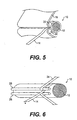
- the material After forming the nonwoven web, the material is rolled onto a master roll, which can then be transported for use or split into smaller sheets or strips used to make smaller rolls of material. These rolls are spiral wound into what is commonly called a pancake roll, represented in FIG. 2. It is important that the initial characteristics of the material obtained upon its manufacture be maintained during subsequent processing and transport. For instance, nonwoven material intended to be manufactured into diapers must be handled in a way such that it arrives at the diaper manufacturer with its initial manufactured characteristics, especially as to product performance.
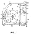
- FIG. 3 shows a compressible sheet 210 pressed by a compression belt 220 at a compression point P, which breaks fibers at that point.
- FIG. 4 shows a compressible sheet 230 pressed by nips 240 at a compression point P, which also breaks fibers at that point. Damage to the nonwoven structure can adversely affect its rebound, strength, stretch and absorbency, among other qualities. In particular, if the delicately entangled fibers are broken or the cells of a foam are crushed, the fluid path is compromised.
- FIG. 2 shows a conventional pancake roll 200 wound with no compression.
- Section B of FIG. 2 shows the fibers of the nonwoven being in their original entangled state. Even winding without compression can create problems in spiral wound rolls in which the inner layers can be unevenly pressed by the outer layers.
- winding compressible material under tension to obtain a larger run of material on each roll is not effective. Placing nonwoven compressible material under tension can also damage the internal fibers by breaking them and thus cause performance of the material to degrade.
- a package comprising: a core; and compressible strip material wound on the core, the wound strip material being compressed to substantially reduce the thickness thereof compared with its thickness when unwound; wherein the pressure on each layer of the strip is substantially uniform throughout the entire package, and the wound strip material is without significant tension.
- the wound strip material has no tension or substantially no tension.
- the wound strip material may be arranged to be without tension beyond that required to wind the material onto the core.
- the wound strip material may be arranged such that any tension in the wound material is less than that which would by itself produce any significant compression of the strip material.
- the strip material is nonwoven material and may for example be open cell foam strip material or nonwoven fibrous material.
- a method of forming a package comprising strip material formed into a roll wound on a core, comprising: feeding a strip of compressible material to a core; and winding the strip onto the core; wherein the winding step includes passing the strip material around the core between the core and a driven belt which extends around the core and which compresses the strip material during winding.
- the driven belt may extend at least partially around the core and preferably the driven belt substantially surrounds the core.
- the winding step includes winding the strip material in a pattern which traverses the length of the core.
- the winding step includes winding the strip material in a pattern of adjacent rolls along the core with stepped interconnecting strip portions between each roll on the core.
- apparatus for forming a package comprising strip material formed into a roll wound on a core
- the apparatus comprising: a frame for supporting a core for the package to be formed; and a drive assembly for winding strip material around the core to form a roll wound on the core; wherein the drive assembly includes a driven belt for compressing the strip material between the belt and the core during winding.
- the apparatus includes a tension adjustment assembly, also referred to as a belt support assembly, for adjusting the tension in the belt in response to diameter growth of the package to provide a constant pressure on each layer of strip material in the package.
- a tension adjustment assembly also referred to as a belt support assembly
- the driven belt of the drive assembly is arranged to surround the core at least partially, and preferably the drive belt is arranged to substantially surround the core during wrapping.
- a package comprising: a core having a length; and strip material wound on the core substantially across its length, wherein the strip material has a thickness, is nonwoven, has substantially no tension, and is compressed to substantially reduce the thickness, wherein the pressure on each layer of the strip is substantially uniform throughout the entire package.
- a method of forming a package wherein strip material is formed into a roll supported by a core comprising: feeding an uncompressed strip of material to a core; and winding the strip onto the core with a driven belt that substantially surrounds the core to wrap the strip around the core with the strip under compression.
- an apparatus for forming a package of open cell foam strip material wound on a core under compression comprising a frame, a longitudinal core supported by the frame, a driven belt supported by the frame to substantially surround the core, a belt support assembly that adjusts the tension in the belt based on diameter growth of the package, and combined with a package of compressed foam strip material wound on the core having a constant pressure on each layer of strip material.
- An aspect of this invention provides a significantly compacted roll of nonwoven material that has material characteristics suitable for an end use manufacturer.
- Another aspect of this invention provides a package that is less expensive to transport and store due to its compacted size.
- An additional aspect of this invention provides a method of winding an uncompressed nonwoven sheet of material into a roll under compression controlled to significantly reduce the thickness of the sheet with no damage to the material.
- the method also includes forming plural compressed rolls on a single core.
- a further aspect of this invention provides an apparatus for compression winding a package in conjunction with a traverse winding assembly.
- Another aspect of the invention provides a package formed of a compressed traverse wound roll or a plurality of pancake rolls on a single core.
- An additional aspect of the invention provides a method of controlling compression of a package of nonwoven compressible material based on the inherent characteristics of the material to maximize compression and minimize material damage.
- a further aspect of the invention is to provide a package in which the material is under substantially uniform pressure throughout.
- the compressed material is not under tension.
- the apparatus for making the package can have a controller that balances compression with the material properties.
- the method of making such a package includes the step of controlling the compression on each layer of the package.
- a package may comprise a core having a length and strip material having a width less than the length of the core wound in a traverse pattern over substantially the length of the core under compression, wherein the strip material is under uniform pressure throughout the entire package.
- the package may also comprise a core having a length and strip material wound on the core under compression in a pattern of a plurality of stacked rolls with stepped interconnected strip portions between each roll on the core, wherein the strip material is under uniform pressure throughout the entire package.
- the package may comprise a core having a length and strip material wound on the core substantially across its length, wherein the strip material has a thickness, is nonwoven, has substantially no tension, and is compressed to substantially reduce the thickness, wherein the pressure on each layer of the strip is substantially uniform throughout the entire package.
- the strip material may be made of nonwoven material.
- the strip may be made of one of fibrous material, air laid material, filtration media, foam, film, mechanical fastening tapes and composites.
- the strip may be continuous and include a plurality of longitudinal strips connected at their ends to form a continuous strip.
- a method of forming a package wherein strip material is formed into a roll supported by a core may comprise feeding an uncompressed strip of material to the core and winding the strip onto the core with a driven belt that substantially surrounds the core to wrap the strip around the core with the strip under compression.
- the method may include winding the strip in a traverse pattern across a length of the core.
- the method may include moving one of the strip and the core to effect the traverse winding.
- the method may include winding the strip in a pattern of spiral wound stacks interconnected by stepped portions of the strip.
- the method may include controlling the winding to form the spiral wound stacks in repeating layers across the length of the core.
- the method may further comprise separating the strip from a larger sheet of material prior to feeding the strip to the core.
- the method may include slitting the strip into plural strips.
- the method may include separating a plurality of strips from the large sheet of material and simultaneously winding the plurality of strips on the core.
- the method may include separating a plurality of strips from the large sheet of material and simultaneously winding the plurality of strips on individual cores.
- the method may include feeding a plurality of strips to the core and winding the plurality of strips onto the core simultaneously.
- the method may include feeding a plurality of strips to a plurality of cores and winding the plurality of strips onto each core simultaneously.
- the method may further comprise using a belt that is at least as wide as the strip to cover, wind and compress the strip onto the core.
- the belt may have a width substantially equal to the resulting wound roll.
- the belt may have a width substantially equal to the strip.
- the method may further comprise connecting plural strips at their ends to form a continuous strip that is wound onto the core.
- a method of forming a package may comprise feeding a sheet of material to a packaging apparatus having at least one core and at least one driven belt that substantially surrounds the core, separating the sheet into a plurality of strips, driving the belt under tension, and winding each strip onto a core with the belt thereby compressing the strip and forming a package under uniform pressure throughout.
- the method may include feeding an uncompressed sheet. Feeding the sheet may include precompressing the sheet.
- the method may further comprise controlling the belt to form a tightly compressed package without damage to the material in the strips.
- Winding the strip may include winding a plurality of strips onto one core. Winding the strip may include winding one strip onto one core. Winding the strip may include traverse winding the strip across the length of the core. Winding the strip may include spiral winding the strip on the core. Winding the strip may include winding the strip in a plurality of spiral wound stacks interconnected by stepped portions of the strip. Winding the strip may include winding a plurality of strips onto a plurality of cores simultaneously.
- the method may further comprise connecting plural strips at their ends to form a continuous strip that is wound onto the core.
- an apparatus for forming a package of strip material wound on a core under compression may comprise a winding device having a frame, a longitudinal core support mounted to the frame, and a driven belt supported by the frame to substantially surround the core; and strip material feeding apparatus disposed adjacent to the winding device and including a traverse feeder that moves the strip material longitudinally with respect to the core, wherein the driven belt is controlled to wind the strip material onto the core under compression.
- the apparatus may further comprise a material separator that separates the strip material from a sheet of material.
- the apparatus may further comprise a controller coupled to the driven belt to adjust the driven speed of the belt and the tension in the belt to control compression of the strip material.
- the strip material feeding apparatus may include a material supply and supply driver that drives the material supply and controls tension in the strip material.
- the apparatus may further comprise a plurality of longitudinal core supports and a plurality of driven belts, and the strip material feeding apparatus may include a traverse feeder associated with each longitudinal core support.
- the apparatus may further comprise a series of rolls supported by the frame to support the driven belt, wherein at least one of the rolls is supported on a movable arm that is selectively movable to release the formed package from the belt.
- an apparatus for forming a package of strip material wound on a core under compression may comprise a winding device comprising a frame, a longitudinal core supported by the frame, and a driven belt supported by the frame to substantially surround the core; and strip material feeding apparatus including a material separator that separates strips from a sheet of material, wherein the separated strip is wound onto the core by the driven belt.
- the apparatus may further comprise a traverse feeder that moves the strip material longitudinally with respect to the core.
- the apparatus may further comprise a controller coupled to the driven belt to adjust the driven speed of the belt and the tension in belt to control compression of the strip material.
- the strip material feeding apparatus may include a material supply and supply driver that drives the material supply and controls tension in the strip material.
- the apparatus may further comprise a plurality of longitudinal core supports and a plurality of driven belts, and the strip material feeding apparatus may feed each separated strip to each longitudinal core support.
- an apparatus for forming a package of strip material wound on a core under compression may comprise a frame, a longitudinal core supported by the frame, a driven belt supported by the frame to substantially surround the core, and a controller coupled to the driven belt that adjusts tension of the belt based on parameters of the strip material so that fibers in the compressed strip material do not break.
- an apparatus for forming a package of open cell foam strip material wound on a core under compression may comprise a frame, a longitudinal core supported by the frame, a driven belt supported by the frame to substantially surround the core, a belt support assembly that adjusts the tension in the belt based on diameter growth of the package, and combined with a package of compressed foam strip material wound on the core having a constant pressure on each layer of strip material.
- the apparatus may further comprise a precompression system including a driven supply belt and a vacuum source that define a feed path for the strip material.
- the strip material may be traverse wound on the core.
- the strip material may be wound in a plurality of pancake rolls on the core.
- An antistatic guard may be mounted on the frame to dissipate static charge from the belt.
- Embodiments of the invention will be described with reference to a package. It is to be understood that this description of a package is intended to cover various sizes of packages, ranging from large mill rolls to small rolls suitable for light industrial applications. It should also be understood that the material is described referring to a sheet or strip that is intended to include various configurations of materials generally formed in a mat, tape, web or elongate form. The strips can range from very narrow, for example several inches or about 10mm, to very wide, for example about ten feet or two meters.
- nonwoven materials which can be similar to those described in the background section of this document.
- the nonwoven material referred to herein includes various materials formed of interconnected fibers that are not woven like a conventional textile. The materials tend to carry relatively large amounts of air between the interstices of the material fibers or elements.
- the nonwovens can include material that is fibrous, air laid, and/or compressible.
- the types of material include filtration media, cellulosic, polyester, polymeric, glass, spun bond, open cell foam, and composites that could include films.
- the compression and packaging techniques could be used on various types of materials including films, foils, plastics, mechanical fastening tape, drawstrings, elastomerics, foams, and even textiles if desired.
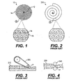
- FIG. 1 A package 10 formed in accordance with an embodiment of this invention is shown in FIG. 1.
- the package 10 includes a core 12 with a strip of material 14 wound around the core 12 under compression, as will be discussed below.
- package 10 holds a significantly longer strip of material 14 than a conventional package 200.
- the strip 14 may be continuous, that is the strip 14 may be formed of a series of interconnected strips to form a continuous strip, which is more desirable in an end use manufacturing assembly so that frequent stopping for strip replenishment is not necessary.
- Various known ways of forming a continuous strip, including splicing, may be used.
- the section A of FIG. 1 shows that the strip 14 is layered with uniform compression.
- the fibers 16 are more compactly arranged due to the removal of air from between the fibers 16.
- the compression is not so great, however, that the fibers 16 are broken or the properties of the strip 14 are changed.
- Various degrees of compression can be obtained depending on the particular material used. In this case, compression of about 6 to 1 is achieved. It will be appreciated that this offers significant savings in terms of storage and transportation and manufacturing efficiency due to a reduction in change over and down time.
- nonwoven materials may be compressed using a uniform pressure that consistently surrounds the material 14 as it is being wound on the core 12 to a certain degree without experiencing deleterious effects on the properties of the nonwoven material.
- a uniform pressure that consistently surrounds the material 14 as it is being wound on the core 12 to a certain degree without experiencing deleterious effects on the properties of the nonwoven material.
- the tension in the wound strip is reduced to a minimum value that is necessary to just carry the material 14 to the compression area between the package 10 and the guide roll, described below. As the winding progresses, it is desirable that the material 14 remains at a constant tension and compression throughout the length of the material 14 within the package 10.
- the material 14 from packages 10 formed in accordance with such embodiments of the invention exhibit no harmful effects from the compression. Further, when opened, the packages 10 gently expand or rebound without exhibiting a popping or springing effect that is difficult to manage in a manufacturing environment. This is a result of compressing the material 14 without tensioning the strips so the potential energy in the strips 14 causes the fibers 16 to expand with respect to each other allowing air into the interstices, and not rebound from tension in the strips 14.
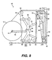
- FIGs. 5 and 6 The basic concept of winding the material 14 while compressing is shown in FIGs. 5 and 6.
- the embodiment seen in FIG. 5 uses a belt 18 that extends substantially the entire length of the core 12.
- the strip of material 14 is fed between a pair of rolls 20 and 22 onto the core 12.
- the belt 18 is driven and wraps the strip of material 14 around the core 12 by friction.
- the strip of material can be any width, and although shown as a thin strip it could extend the length of the core.
- the belt 18 is formed as an endless sheet of material that has a high tensile strength.
- a suitable material is a woven urethane bottom that functions as the drive surface and a urethane top surface that is "sticky" or has a high coefficient of friction that contacts the strip of material.
- a preferred material for belt 18 is impervious PVC. It is also possible to use a belt that is formed as a screen, is semi-permeable or is perforated to allow visual inspection of the package 10 during formation. Of course, any other suitable material may be used for the belt 18. It is also contemplated that the belt 18 can be formed as plural belts, each forming a segment of a belt system that forms a full circle around the core 12.
- FIG. 6 shows an alternative belt arrangement in which a narrow belt 24 that is approximately the width of the strip 14 is used. In this case, the belt 24 still fully surrounds the strip 14 as it is fed between rolls 26 and 28 to be wound on the core 12.
- FIGs. 7 and 8 show a winding apparatus 40 in accordance with one embodiment of the invention.
- the winding apparatus 40 includes a frame 42 supported on a surface and a core support 44 that supports the core 12 of the package 10.
- the core support 44 can take various forms including an elongate spindle or a pair of axles, for example.
- the core support 44 is carried on a discharge rail 45.
- the frame 42 supports a belt support system, in this case rolls, that support and drive the belt 18.
- a belt tensioning device 46 is also provided.
- the belt 18 support system is formed by a series of rolls, which could also be pulleys, including rolls 48 and 50 at the base of the frame 42, rolls 52 and 54 at the top of the frame 42, feeder rolls 56, 58, 60, and 62 and tensioning roll 64.
- Rolls 56 and 58 are carried on a pivoting upper arm 66
- rolls 60 and 62 are carried on a pivoting lower arm 68 connected at pivot joint 70.
- Arms 66 and 68 are controlled by pistons 72 and 74 that are mounted to a support rail 78.
- One or more of the rolls are driven so as to turn the endless belt 18 around the path of rolls. In this case, for example, roll 50 is driven. However, another roll in the assembly could function as the driving roll.
- Belt tensioning device 46 also consists of a series of rolls, or pulleys, mounted on a driven rod 80.
- Rod 80 can be any driven device, but in this case is a pneumatic piston with a pulley 82 on one end.
- Rolls 84, 86, and 88 are mounted on the frame 42 and form a path for a tensioning strap 90.
- the strap 90 extends from tensioning roll 64 around rolls 88, 86, and 84 to pulley 82 and is then mounted to roll 52 or any other fixed point on the frame 42.
- the tensioning device 46 may be manually controlled or may be connected to a controller C that is programmed to control driven device 80 to tension and release the belt 18, as discussed below.
- the core 12 is supported so that it can move naturally in response to the increasing diameter of the package 10.
- the controller C can control the position of the core 12 to affect the tension in the belt 18 and, thus, the pressure on the package 10.
- the controller C detects the core 12 speed and then determines the belt 18 tension.
- the position of the core 12 can be then moved to counterbalance the tension in the belt 18. This control is especially useful if the material 14 is buckling between the rolls 58 and 60.
- the core 12 position can also be controlled to assist in removal of the package 10, as discussed below.
- FIG. 7 shows a metal screen 92, preferably covered by a shield such as Plexiglas, disposed on one side of the apparatus 40 that dissipates static charge from the belt 18 by gathering charge as the belt 18 passes by the screen 92.
- a shield such as Plexiglas
- an edge guide 94 can also be provided to monitor the position of the edge of the belt 18 and control wandering. As the belt 18 rotates at high speeds, it can have a tendency to wander to one side or the other. Such wandering adversely affects the tension in the belt 18 and compromises the uniform pressure and growth of the package 10.
- An example of a suitable edge guide is an optical position detector.
- a commercially available system suitable for use with the apparatus 40 is an Fife edge guide system, which is a commercially available dynamic guide that repositions the center line of the belt 18 by twisting the belt 18 by adjusting the position of one or more of the rolls.
- the belt 18 extends around rolls 48, 64, 50, 52, 54, 56, and 58 and then around core 12 of package 10 and out to rolls 60, 62, and back to roll 48 in an endless loop.
- the belt 18 receives an end of the strip 14 between rolls 58 and 60 and catches the strip 14 between the belt 18 and the core 12.
- the strip 14 is wound around the core 12.
- the belt 18 expands around the material 14 to exert an even compressive force on the package 10. The expansion is accommodated by the belt tensioning device 46.
- the belt tensioning device 46 operates as follows. The tension in the belt 18 is varied based on the position of roll 64. Roll 64 rides on support rail 78. The position of roll 64 is determined by the tensioning strap 90, which travels from roll 64 around rolls 88, 86, and 84 to pulley 82. Pulley 82 is moved by driven rod 80. FIG. 7 shows the fully retracted position of rod 80 in which the roll 64 is at its lowermost position and the package 10 is fully formed. To shorten the belt 18 around the package, the roll 64 is pulled upward on rail 78 by extending rod 80 and lowering pulley 82.
- the length of the strip 14 is not changed after it is applied to the package 10 by allowing the diameter to expand, thus potentially damaging the material by inducing tension in the material of the strip 14.
- the tension in the belt 18 is maintained to match the expansion forces generated at all points throughout the package 10. It is apparent that the tension in the belt 18 will increase as the diameter of the package 10 increases. So, the tension in the belt 18 will, in theory, increase in direct proportion to the diameter to maintain a constant pressure on the surface of the package 10.
- the pressure must vary to accommodate the changing expansion forces generated by the package 10, especially as the expansion forces change based on the amount of material 14 supported on the core 12 and the inherent spring force generated by the material 14.
- the tension in the belt 18 must be properly controlled in view of these factors to resist the tendency of the strips 14 to increase or decrease in length as the diameter of the package 10 at that particular layer tends to increase or decrease due to subtle differences in expansion or collapse of the package. If the belt 18 is improperly tensioned, the package 10 will tend to expand or collapse thus causing the strips 14 to increase or decrease in length, which could damage the material, especially since there is high friction between the layers of a nonwoven that entrap air and resist slipping.
- the layers of strips 14 will tend to expand or contract to maintain a constant thickness between the layers as the forces will be distributed between the layers thus averaging out the compressive forces and the actual amount of compression.
- roll 64 is pulled by tensioning strap 90 to its uppermost position, as seen in FIG. 8. This shortens the belt 18 to its minimum extent and pushes arms 66 and 68 to pivot about joint 70, thereby compressing pistons 72 and 74. Package 10 is then permitted to travel outward on discharge rail 45 for removal from the apparatus. When the belt 18 is slackened, the pistons 72 and 74 urge the arms 66 and 68 into the closed position.
- the rolls 58 and 60 be disposed close together to avoid the material 14 from bulging outward between rolls 58 and 60. However, depending on the degree of desired compression, it is not necessary that rolls 58 and 60 be disposed close together.
- the degree of compression is determined by using parameters of the material 14 being wound. Based on prior testing of the material to determine the point at which the fibers 16 break down or other characteristics of the material change, the belt 18 is tensioned to impart the maximum pressure the package 10 can withstand without damaging the material 14, particularly the fibers 16. By this, the most efficient size package 10 can be produced. As consistent pressure is applied by the belt 18, compression is substantially uniform throughout each layer of material 14.
- the material supply used to supply the strip 14 to the apparatus 40 can vary.
- FIGS. 9-11 show three possible arrangements. It is also possible to supply material directly from the point of manufacture, in other words to use the apparatus 40 to initially package the material on a master roll.
- the material supply includes a wound sheet of material 100 supported on a supply support 102.
- the supply support 102 includes a supply driver 104 that drives the material supply 100 and controls the tension of the strip 14. It is preferred to supply the strip 14 with minimal tension, ideally no significant tension. The ideal tension will supply the material 14 without creating slack or becoming taut. For example, a preferred negligible tension would be one ounce per inch. Any type of supply support 102 can be provided as long as a stable support is present.
- the supply driver 104 can also take any form, such as a driven roll. It is not necessary to provide a supply driver 104, but its presence assists in smoothly supplying the material 14 with negligible tension.
- the material supply may also include a separator 106, which may be any device that divides the sheet of material 100 into strips.
- a separator 106 may be any device that divides the sheet of material 100 into strips.
- One such device is a slitter.
- the material supply 100 may already be separated into strips.
- FIG. 9 shows an arrangement in which each strip 14 is fed to an individual winding apparatus 40. By this, a plurality of packages 10 can be made simultaneously.
- FIG. 10 shows an arrangement in which each strip 14 is fed to a single core 12. By this, a plurality of rolls 10 can be formed as a single package 110. In this case, a single belt 18 or multiple belts can be used.
- FIG. 11 shows an arrangement in which a single strip 14 is fed for traverse winding across the length of a single core 12 to form a roll or spool 120.
- one of the supply 100 or the core 12 is moved so that the strip 14 is wound across substantially the entire length of the core 12. This enables a large amount of material to be carried on a single core.
- FIG. 11 shows the core of package 120 moving, however, it is also possible to move the supply 100 or to have a traverse feeder that moves the strip 14. Such traverse winding is also possible with the arrangements in FIGs. 9 and 10.
- step winding in which individual spiral wound rolls are wound on a core interconnected with strips. The winding in this case is accomplished in a stepped fashion so that the rolls are wound in sequence across the core, building each stack gradually. This technique is described in U.S. Patent Re. 32,608.
- the material 14 is not precompressed, it may be desirable in certain situations to precompress the strip 14. In that case, the precompression would be effected with a gentle or gradual compression so as not to damage the material, as occurred in the prior art. For example, it is possible to employ a series of nips progressively spaced closer and closer together to achieve a gentle precompression prior to feeding the material to the belt compressing device. It is also possible to compress the material with a belt carried on a drum.
- FIG. 12 shows a vacuum precompression system 130 including a frame 132 that supports a carriage 134 on a rail 136 and a driving mechanism 138, in this case a driven threaded rod.
- the carriage 134 slides transversely with respect to the frame 132 and the winding apparatus 40 to feed the strip 14 either traversely to form a spiral wound package or in a stepped fashion to form plural pancake stacks.
- the carriage 134 supports a driven belt 140 that extends between a plurality of rolls 142, at least one of which is preferably driven to provide an even supply speed to the material and avoid tensioning or bunching the material as it is being fed to the winding apparatus 40.
- a vacuum drum 144 connected to a vacuum source V is mounted adjacent the driven belt 140. The strip of material 14 is fed between the belt 140 and the vacuum drum 144 thereby drawing air from the material to cause compression. This precompression assists in achieving a highly compressed package 10 but is not necessary to form a package 10 in accordance with this invention.
- the same apparatus described above can be used to unwind the package 10 at an end use station so that the package 10 can be accurately driven by a belt based on the measured tension at the pay-off or measured required line speed.
- the package 10 can be braked and driven at exactly the required speed without tensioning the strip 14 so that the strip 14 can be paid off at a very low or minimum tension.
- expansion of the package 10 can be controlled precisely in a symmetrical manner to the winding action to prevent uncontrolled expansion of the layers creating localized stretching and potential damage of the material 14.
- packages 10 wound by this method without tension induced in the strips 14 naturally hold their shape and are formed as stable structures due to the coefficient of friction between the layers.
- the packages 10 in accordance with embodiments of this invention do not necessarily require exterior wrapping as they resist uncontrolled expansion and do not exhibit a springing or popping effect when unbound.
- the types of packages that can be made using this method and/or this apparatus include rolls carrying extremely long lengths of material.
- the strip of material 14 may range from 5,000 feet to 100,000 feet or more.
- the package 10 may be a small roll of several feet diameter or a large roll, 3 feet wide with a diameter of 4 feet, for example.
- the material can have any thickness.
- the method is particularly suited for strips having a thicknesses of about 5mm, 3mm, or 1 mm, for example.
- the width of the strip may also vary and can range from the length of the core to thin strips of 25cm or 10cm.
- the material may also have various weights.
- the weight may range from 20 grams per square meter (gsm) to 500 gsm or 40 to 50 gsm.
- the method is particularly suited for high speed operation, as in an industrial setting.
- the material may be wound at speeds up to 500 meters per minute.
- the method and apparatus are suitable for a wide variety of materials, especially compressible materials.
- the method may be used to make single or multiple packages that are packaged singly or together.
- the apparatus may be adapted to accommodate different compression requirements and may vary based on different type of supply arrangements. It may be used at the initial phase of forming the material and creating a master roll and/or may be used in downstream operations including separating smaller widths of material from the master roll or even by an end use manufacturer that handles only small rolls of material.
Landscapes
- Nonwoven Fabrics (AREA)
- Auxiliary Devices For And Details Of Packaging Control (AREA)
Applications Claiming Priority (4)
| Application Number | Priority Date | Filing Date | Title |
|---|---|---|---|
| US660645 | 1991-02-25 | ||
| US43829303P | 2003-01-07 | 2003-01-07 | |
| US438293P | 2003-01-07 | ||
| US10/660,645 US20040050988A1 (en) | 2002-09-12 | 2003-09-12 | Method and apparatus for packing material under compression and the package made thereby |
Publications (1)
| Publication Number | Publication Date |
|---|---|
| EP1459984A1 true EP1459984A1 (de) | 2004-09-22 |
Family
ID=32659495
Family Applications (1)
| Application Number | Title | Priority Date | Filing Date |
|---|---|---|---|
| EP04250007A Withdrawn EP1459984A1 (de) | 2003-01-07 | 2004-01-05 | Verfahren und Vorrichtung zum Verpacken von komprimierten Bahnen aus Vliesmaterial und die dadurch erhaltene Packung |
Country Status (3)
| Country | Link |
|---|---|
| US (1) | US20040050988A1 (de) |
| EP (1) | EP1459984A1 (de) |
| CA (1) | CA2454284A1 (de) |
Families Citing this family (3)
| Publication number | Priority date | Publication date | Assignee | Title |
|---|---|---|---|---|
| DE102006052298A1 (de) * | 2006-11-03 | 2008-05-08 | Oerlikon Textile Gmbh & Co. Kg | Verfahren und Vorrichtung zum Abwickeln einer textilen Wattebahn |
| US20110162989A1 (en) * | 2010-01-06 | 2011-07-07 | Ducker Paul M | Ultra thin laminate with particulates in dense packages |
| EP3366381A1 (de) | 2017-02-22 | 2018-08-29 | Primetals Technologies Austria GmbH | Transportvorrichtung und verfahren zum transportieren eines coils |
Citations (7)
| Publication number | Priority date | Publication date | Assignee | Title |
|---|---|---|---|---|
| US2650703A (en) * | 1948-03-10 | 1953-09-01 | Norsk Stalull As | Steel wool packet |
| DE910754C (de) * | 1950-01-23 | 1954-05-06 | Tmm Research Ltd | Wickelvorrichtung fuer Textilmaschinen |
| US4094727A (en) * | 1976-12-17 | 1978-06-13 | Burroughs Corporation | Sheet splicer |
| US4413792A (en) * | 1978-09-07 | 1983-11-08 | Oconnor Lawrence | Apparatus for automatic traverse winding of tapes on a cylindrical core |
| US4759512A (en) * | 1986-04-22 | 1988-07-26 | American Fabrics Company | Multiple winding machine for lace bands and the like |
| EP0649807A2 (de) * | 1993-10-21 | 1995-04-26 | Sumitomo Rubber Industries Limited | Verfahren und Vorrichtung zum Aufspulen eines schmalen Bandes |
| DE19639402A1 (de) * | 1996-09-25 | 1998-03-26 | Rieter Ag Maschf | Wickelvorrichtung |
Family Cites Families (34)
| Publication number | Priority date | Publication date | Assignee | Title |
|---|---|---|---|---|
| US546009A (en) * | 1895-09-10 | John w | ||
| US1772164A (en) * | 1924-04-12 | 1930-08-05 | P M Clark | Cotton baling |
| US2353821A (en) * | 1939-02-13 | 1944-07-18 | Paper Patents Co | Apparatus for making compressed wadding rolls |
| US2742240A (en) * | 1953-04-01 | 1956-04-17 | Gustin Bacon Mfg Co | Mat winding machine |
| US2900980A (en) * | 1954-09-30 | 1959-08-25 | Kimberly Clark Co | Cellulosic product |
| DE2211076A1 (de) * | 1972-03-08 | 1973-09-20 | Waldmann Verpackung Kg | Wickelvorrichtung zum aufwickeln von bahnfoermigem wickelgut |
| US3978257A (en) * | 1973-08-06 | 1976-08-31 | Kimberly-Clark Corporation | Internally adhesively bonded fibrous web |
| US3964235A (en) * | 1973-11-02 | 1976-06-22 | Owens-Corning Fiberglas Corporation | Roll-up compressive packaging apparatus |
| US4100324A (en) * | 1974-03-26 | 1978-07-11 | Kimberly-Clark Corporation | Nonwoven fabric and method of producing same |
| US4109353A (en) * | 1974-12-27 | 1978-08-29 | Kimberly-Clark Corporation | Apparatus for forming nonwoven web |
| US4127637A (en) * | 1975-03-13 | 1978-11-28 | Scott Paper Co. | Method of manufacturing a dry-formed, embossed adhesively bonded, nonwoven fibrous sheet |
| US4093146A (en) * | 1975-03-24 | 1978-06-06 | Fmc Corporation | Winding method and apparatus for strapping and strapping package |
| US3973068A (en) * | 1975-10-28 | 1976-08-03 | Kimberly-Clark Corporation | Soft, nonwoven web having high intensity and low intensity bonds and a lubricant on the surfaces of the synthetic filaments comprising said |
| US4034928A (en) * | 1976-06-29 | 1977-07-12 | Union Carbide Corporation | Method and apparatus for producing coreless roll assemblies of separable bags |
| US4137697A (en) * | 1977-03-18 | 1979-02-06 | International Harvester Company | Bale density structure for cylindrical balers |
| US4114530A (en) * | 1977-06-23 | 1978-09-19 | Owens-Corning Fiberglas Corporation | Apparatus for packaging compressible strips |
| US4477035A (en) * | 1982-02-04 | 1984-10-16 | Oconnor Lawrence | Winding a package of tape |
| CH663602A5 (de) * | 1983-09-15 | 1987-12-31 | Peter Balzer | Verfahren zum wickeln von erzeugnissen aus flexiblem material und wickelvorrichtung zur ausfuehrung des verfahrens. |
| US4602471A (en) * | 1985-05-28 | 1986-07-29 | Owens-Corning Fiberglas Corporation | Roll-up method and apparatus for mineral fiber pack |
| US5058820A (en) * | 1987-01-30 | 1991-10-22 | Canon Kabushiki Kaisha | Strip-like member take-up device |
| US5129208A (en) * | 1990-09-05 | 1992-07-14 | Vermeer Manufacturing Company | Apparatus for feeding wrap material into a bale-forming chamber for wrapping a large round bale |
| FR2685904A1 (fr) * | 1992-01-07 | 1993-07-09 | Saint Gobain Isover | Rouleau de matelas fibreux comprime, methode et dispositif pour l'obtenir. |
| US5381982A (en) * | 1992-11-04 | 1995-01-17 | Beloit Technologies, Inc. | Belted sheet transfer device |
| US5305963A (en) * | 1992-12-03 | 1994-04-26 | Schuller International, Inc. | Method and apparatus for forming rolls from strips of compressible material |
| US5387284A (en) * | 1994-03-07 | 1995-02-07 | James River Paper Company, Inc. | Apparatus and method for forming coreless paper roll products |
| US5419253A (en) * | 1994-03-14 | 1995-05-30 | New Holland North America, Inc. | Round bale wrapping method including wrapping with self-adhering tape |
| US5832696A (en) * | 1994-09-21 | 1998-11-10 | Owens Corning Fiberglas Technology, Inc. | Method and apparatus for packaging compressible insulation material |
| JP3609170B2 (ja) * | 1995-10-05 | 2005-01-12 | 富士写真フイルム株式会社 | ウェブ巻取装置 |
| IT1281197B1 (it) * | 1995-12-04 | 1998-02-17 | Politex Spa | Macchina per la formazione di rotoli di ovatta di forma compatta |
| JPH1072150A (ja) * | 1996-08-30 | 1998-03-17 | Ykk Corp | テープ状体の巻取方法およびその巻取装置 |
| US5842663A (en) * | 1997-02-06 | 1998-12-01 | Kt Industries Inc. | Winding of tape into pads |
| US6021622A (en) * | 1998-06-19 | 2000-02-08 | New Holland North America, Inc. | Round bale wrapping apparatus |
| US6290164B1 (en) * | 2000-03-01 | 2001-09-18 | Kt Equipment (International) Inc. | Method and apparatus for supplying strip material |
| US6343763B1 (en) * | 2000-07-21 | 2002-02-05 | Kt Equipment (International) Inc. | Transferring winding from a filled cylindrical package of an elongate material to an empty core |
-
2003
- 2003-09-12 US US10/660,645 patent/US20040050988A1/en not_active Abandoned
- 2003-12-29 CA CA002454284A patent/CA2454284A1/en not_active Abandoned
-
2004
- 2004-01-05 EP EP04250007A patent/EP1459984A1/de not_active Withdrawn
Patent Citations (7)
| Publication number | Priority date | Publication date | Assignee | Title |
|---|---|---|---|---|
| US2650703A (en) * | 1948-03-10 | 1953-09-01 | Norsk Stalull As | Steel wool packet |
| DE910754C (de) * | 1950-01-23 | 1954-05-06 | Tmm Research Ltd | Wickelvorrichtung fuer Textilmaschinen |
| US4094727A (en) * | 1976-12-17 | 1978-06-13 | Burroughs Corporation | Sheet splicer |
| US4413792A (en) * | 1978-09-07 | 1983-11-08 | Oconnor Lawrence | Apparatus for automatic traverse winding of tapes on a cylindrical core |
| US4759512A (en) * | 1986-04-22 | 1988-07-26 | American Fabrics Company | Multiple winding machine for lace bands and the like |
| EP0649807A2 (de) * | 1993-10-21 | 1995-04-26 | Sumitomo Rubber Industries Limited | Verfahren und Vorrichtung zum Aufspulen eines schmalen Bandes |
| DE19639402A1 (de) * | 1996-09-25 | 1998-03-26 | Rieter Ag Maschf | Wickelvorrichtung |
Also Published As
| Publication number | Publication date |
|---|---|
| CA2454284A1 (en) | 2004-07-07 |
| US20040050988A1 (en) | 2004-03-18 |
Similar Documents
| Publication | Publication Date | Title |
|---|---|---|
| JP4717353B2 (ja) | 触感品質が向上したクレープティッシュを製造するための、ウェブの取り扱いを改善した方法及び装置 | |
| JP6537507B2 (ja) | ロフティ特性、弾性特性及び高強度特性のうちの少なくとも1つを有するスパンレイドウェブ | |
| US6479061B2 (en) | Absorbent structure including a thin, calendered airlaid composite and a process for making the composite | |
| JP5967074B2 (ja) | 高柔軟性吸収性積層体およびその製造方法 | |
| CN102048616B (zh) | 选择性地针刺非织造幅材形成的棉塞 | |
| US6368609B1 (en) | Absorbent structure including a thin, calendered airlaid composite and a process for making the composite | |
| RU2759695C1 (ru) | Способ спрессовывания санитарно-гигиенических бумажных изделий из структурированного материала | |
| RU2670170C1 (ru) | Способ и устройство для образования пачки, содержащей стопку абсорбирующего бумажного материала салфеток и упаковку | |
| WO1998052745A1 (en) | Thin absorbent pads for food products | |
| JPH02296620A (ja) | ロール状の紙製品を包装する方法及び包装された紙製品 | |
| MXPA05005012A (es) | Productos de tisu enrollados que tienen alto volumen, suavidad y firmeza. | |
| JP2628391B2 (ja) | 容易にほぐされ、ウェブ造形される紙製品 | |
| RU2677807C1 (ru) | Пачка, содержащая стопку абсорбирующего бумажного материала салфеток и упаковку | |
| US7673573B2 (en) | Manufacturing system and manufacturing method for sheet-like structure | |
| RU2339355C2 (ru) | Упакованный, закрытый пленкой тампон | |
| EP1459984A1 (de) | Verfahren und Vorrichtung zum Verpacken von komprimierten Bahnen aus Vliesmaterial und die dadurch erhaltene Packung | |
| WO1992007762A1 (en) | Method for packaging and shipping fiber materials | |
| RU2678176C1 (ru) | Пачка, содержащая стопку абсорбирующего бумажного материала салфеток и упаковку | |
| KR20160141794A (ko) | 재료 웹들을 후속 처리 장치에 공급하는 장치 및 방법 | |
| JP2007312967A (ja) | フェイスマスク及びその製造方法 | |
| KR20210036467A (ko) | 부직포형 펄프리스 흡수코어 제조방법 및 그 방법에 의해 제조된 부직포형 펄프리스 흡수코어 | |
| CN107428486B (zh) | 卷绕具有三维特征的基底的方法 | |
| JP5452949B2 (ja) | ロール状シートの製造方法、及び、ロール状シートの製造装置 | |
| CN110088004B (zh) | 压缩薄棉纸捆束的方法 | |
| JPS5849473B2 (ja) | センイシノパツケ−ジ オヨビ ソノセイゾウホウ |
Legal Events
| Date | Code | Title | Description |
|---|---|---|---|
| PUAI | Public reference made under article 153(3) epc to a published international application that has entered the european phase |
Free format text: ORIGINAL CODE: 0009012 |
|
| AK | Designated contracting states |
Kind code of ref document: A1 Designated state(s): AT BE BG CH CY CZ DE DK EE ES FI FR GB GR HU IE IT LI LU MC NL PT RO SE SI SK TR |
|
| AX | Request for extension of the european patent |
Extension state: AL LT LV MK |
|
| RIN1 | Information on inventor provided before grant (corrected) |
Inventor name: O'CONNOR, LAWRENCE |
|
| 17P | Request for examination filed |
Effective date: 20050321 |
|
| AKX | Designation fees paid |
Designated state(s): AT BE BG CH CY CZ DE DK EE ES FI FR GB GR HU IE IT LI LU MC NL PT RO SE SI SK TR |
|
| 17Q | First examination report despatched |
Effective date: 20070207 |
|
| STAA | Information on the status of an ep patent application or granted ep patent |
Free format text: STATUS: THE APPLICATION IS DEEMED TO BE WITHDRAWN |
|
| 18D | Application deemed to be withdrawn |
Effective date: 20070820 |