EP1458514B1 - Dispositif de soudage pour materiau d'emballage - Google Patents
Dispositif de soudage pour materiau d'emballage Download PDFInfo
- Publication number
- EP1458514B1 EP1458514B1 EP02782610A EP02782610A EP1458514B1 EP 1458514 B1 EP1458514 B1 EP 1458514B1 EP 02782610 A EP02782610 A EP 02782610A EP 02782610 A EP02782610 A EP 02782610A EP 1458514 B1 EP1458514 B1 EP 1458514B1
- Authority
- EP
- European Patent Office
- Prior art keywords
- ferromagnetic
- packaging material
- welding
- magnetic field
- layer
- Prior art date
- Legal status (The legal status is an assumption and is not a legal conclusion. Google has not performed a legal analysis and makes no representation as to the accuracy of the status listed.)
- Expired - Lifetime
Links
- 239000005022 packaging material Substances 0.000 title claims abstract description 22
- 238000007789 sealing Methods 0.000 title 1
- 238000003466 welding Methods 0.000 claims abstract description 36
- 230000005294 ferromagnetic effect Effects 0.000 claims abstract description 34
- 238000010438 heat treatment Methods 0.000 claims abstract description 26
- 230000005291 magnetic effect Effects 0.000 claims abstract description 21
- 230000005674 electromagnetic induction Effects 0.000 claims abstract description 7
- 229920001169 thermoplastic Polymers 0.000 claims abstract description 3
- 239000004416 thermosoftening plastic Substances 0.000 claims abstract description 3
- 230000001131 transforming effect Effects 0.000 claims abstract description 3
- XAGFODPZIPBFFR-UHFFFAOYSA-N aluminium Chemical compound [Al] XAGFODPZIPBFFR-UHFFFAOYSA-N 0.000 claims description 17
- 229910052782 aluminium Inorganic materials 0.000 claims description 16
- 239000004411 aluminium Substances 0.000 claims description 5
- RYGMFSIKBFXOCR-UHFFFAOYSA-N Copper Chemical compound [Cu] RYGMFSIKBFXOCR-UHFFFAOYSA-N 0.000 claims description 4
- 229910052802 copper Inorganic materials 0.000 claims description 4
- 239000010949 copper Substances 0.000 claims description 4
- 230000005465 channeling Effects 0.000 abstract description 3
- -1 Polyéthylène Polymers 0.000 description 17
- 239000004698 Polyethylene Substances 0.000 description 9
- 229920000573 polyethylene Polymers 0.000 description 9
- 229920001577 copolymer Polymers 0.000 description 7
- 229910052751 metal Inorganic materials 0.000 description 6
- 239000002184 metal Substances 0.000 description 6
- 239000011888 foil Substances 0.000 description 5
- 229920000642 polymer Polymers 0.000 description 5
- 239000012815 thermoplastic material Substances 0.000 description 5
- 239000004033 plastic Substances 0.000 description 4
- 229920003023 plastic Polymers 0.000 description 4
- 229910000859 α-Fe Inorganic materials 0.000 description 4
- 238000006073 displacement reaction Methods 0.000 description 3
- 238000005476 soldering Methods 0.000 description 3
- 229910000831 Steel Inorganic materials 0.000 description 2
- 230000015572 biosynthetic process Effects 0.000 description 2
- 239000000463 material Substances 0.000 description 2
- 238000004806 packaging method and process Methods 0.000 description 2
- 239000010959 steel Substances 0.000 description 2
- 238000009792 diffusion process Methods 0.000 description 1
- 230000000694 effects Effects 0.000 description 1
- 230000006698 induction Effects 0.000 description 1
- 230000001939 inductive effect Effects 0.000 description 1
- 229910000679 solder Inorganic materials 0.000 description 1
- 230000001052 transient effect Effects 0.000 description 1
Images


Classifications
-
- B—PERFORMING OPERATIONS; TRANSPORTING
- B23—MACHINE TOOLS; METAL-WORKING NOT OTHERWISE PROVIDED FOR
- B23K—SOLDERING OR UNSOLDERING; WELDING; CLADDING OR PLATING BY SOLDERING OR WELDING; CUTTING BY APPLYING HEAT LOCALLY, e.g. FLAME CUTTING; WORKING BY LASER BEAM
- B23K13/00—Welding by high-frequency current heating
- B23K13/01—Welding by high-frequency current heating by induction heating
- B23K13/02—Seam welding
- B23K13/025—Seam welding for tubes
-
- B—PERFORMING OPERATIONS; TRANSPORTING
- B23—MACHINE TOOLS; METAL-WORKING NOT OTHERWISE PROVIDED FOR
- B23K—SOLDERING OR UNSOLDERING; WELDING; CLADDING OR PLATING BY SOLDERING OR WELDING; CUTTING BY APPLYING HEAT LOCALLY, e.g. FLAME CUTTING; WORKING BY LASER BEAM
- B23K13/00—Welding by high-frequency current heating
- B23K13/01—Welding by high-frequency current heating by induction heating
- B23K13/02—Seam welding
-
- B—PERFORMING OPERATIONS; TRANSPORTING
- B29—WORKING OF PLASTICS; WORKING OF SUBSTANCES IN A PLASTIC STATE IN GENERAL
- B29C—SHAPING OR JOINING OF PLASTICS; SHAPING OF MATERIAL IN A PLASTIC STATE, NOT OTHERWISE PROVIDED FOR; AFTER-TREATMENT OF THE SHAPED PRODUCTS, e.g. REPAIRING
- B29C65/00—Joining or sealing of preformed parts, e.g. welding of plastics materials; Apparatus therefor
- B29C65/02—Joining or sealing of preformed parts, e.g. welding of plastics materials; Apparatus therefor by heating, with or without pressure
- B29C65/34—Joining or sealing of preformed parts, e.g. welding of plastics materials; Apparatus therefor by heating, with or without pressure using heated elements which remain in the joint, e.g. "verlorenes Schweisselement"
- B29C65/36—Joining or sealing of preformed parts, e.g. welding of plastics materials; Apparatus therefor by heating, with or without pressure using heated elements which remain in the joint, e.g. "verlorenes Schweisselement" heated by induction
- B29C65/3604—Joining or sealing of preformed parts, e.g. welding of plastics materials; Apparatus therefor by heating, with or without pressure using heated elements which remain in the joint, e.g. "verlorenes Schweisselement" heated by induction characterised by the type of elements heated by induction which remain in the joint
- B29C65/3656—Joining or sealing of preformed parts, e.g. welding of plastics materials; Apparatus therefor by heating, with or without pressure using heated elements which remain in the joint, e.g. "verlorenes Schweisselement" heated by induction characterised by the type of elements heated by induction which remain in the joint being a layer of a multilayer part to be joined, e.g. for joining plastic-metal laminates
-
- B—PERFORMING OPERATIONS; TRANSPORTING
- B29—WORKING OF PLASTICS; WORKING OF SUBSTANCES IN A PLASTIC STATE IN GENERAL
- B29C—SHAPING OR JOINING OF PLASTICS; SHAPING OF MATERIAL IN A PLASTIC STATE, NOT OTHERWISE PROVIDED FOR; AFTER-TREATMENT OF THE SHAPED PRODUCTS, e.g. REPAIRING
- B29C65/00—Joining or sealing of preformed parts, e.g. welding of plastics materials; Apparatus therefor
- B29C65/02—Joining or sealing of preformed parts, e.g. welding of plastics materials; Apparatus therefor by heating, with or without pressure
- B29C65/34—Joining or sealing of preformed parts, e.g. welding of plastics materials; Apparatus therefor by heating, with or without pressure using heated elements which remain in the joint, e.g. "verlorenes Schweisselement"
- B29C65/36—Joining or sealing of preformed parts, e.g. welding of plastics materials; Apparatus therefor by heating, with or without pressure using heated elements which remain in the joint, e.g. "verlorenes Schweisselement" heated by induction
- B29C65/3668—Joining or sealing of preformed parts, e.g. welding of plastics materials; Apparatus therefor by heating, with or without pressure using heated elements which remain in the joint, e.g. "verlorenes Schweisselement" heated by induction characterised by the means for supplying heat to said heated elements which remain in the join, e.g. special induction coils
-
- B—PERFORMING OPERATIONS; TRANSPORTING
- B29—WORKING OF PLASTICS; WORKING OF SUBSTANCES IN A PLASTIC STATE IN GENERAL
- B29C—SHAPING OR JOINING OF PLASTICS; SHAPING OF MATERIAL IN A PLASTIC STATE, NOT OTHERWISE PROVIDED FOR; AFTER-TREATMENT OF THE SHAPED PRODUCTS, e.g. REPAIRING
- B29C65/00—Joining or sealing of preformed parts, e.g. welding of plastics materials; Apparatus therefor
- B29C65/02—Joining or sealing of preformed parts, e.g. welding of plastics materials; Apparatus therefor by heating, with or without pressure
- B29C65/34—Joining or sealing of preformed parts, e.g. welding of plastics materials; Apparatus therefor by heating, with or without pressure using heated elements which remain in the joint, e.g. "verlorenes Schweisselement"
- B29C65/36—Joining or sealing of preformed parts, e.g. welding of plastics materials; Apparatus therefor by heating, with or without pressure using heated elements which remain in the joint, e.g. "verlorenes Schweisselement" heated by induction
- B29C65/3672—Joining or sealing of preformed parts, e.g. welding of plastics materials; Apparatus therefor by heating, with or without pressure using heated elements which remain in the joint, e.g. "verlorenes Schweisselement" heated by induction characterised by the composition of the elements heated by induction which remain in the joint
- B29C65/3676—Joining or sealing of preformed parts, e.g. welding of plastics materials; Apparatus therefor by heating, with or without pressure using heated elements which remain in the joint, e.g. "verlorenes Schweisselement" heated by induction characterised by the composition of the elements heated by induction which remain in the joint being metallic
- B29C65/368—Joining or sealing of preformed parts, e.g. welding of plastics materials; Apparatus therefor by heating, with or without pressure using heated elements which remain in the joint, e.g. "verlorenes Schweisselement" heated by induction characterised by the composition of the elements heated by induction which remain in the joint being metallic with a polymer coating
-
- B—PERFORMING OPERATIONS; TRANSPORTING
- B29—WORKING OF PLASTICS; WORKING OF SUBSTANCES IN A PLASTIC STATE IN GENERAL
- B29C—SHAPING OR JOINING OF PLASTICS; SHAPING OF MATERIAL IN A PLASTIC STATE, NOT OTHERWISE PROVIDED FOR; AFTER-TREATMENT OF THE SHAPED PRODUCTS, e.g. REPAIRING
- B29C66/00—General aspects of processes or apparatus for joining preformed parts
- B29C66/01—General aspects dealing with the joint area or with the area to be joined
- B29C66/05—Particular design of joint configurations
- B29C66/10—Particular design of joint configurations particular design of the joint cross-sections
- B29C66/11—Joint cross-sections comprising a single joint-segment, i.e. one of the parts to be joined comprising a single joint-segment in the joint cross-section
- B29C66/112—Single lapped joints
- B29C66/1122—Single lap to lap joints, i.e. overlap joints
-
- B—PERFORMING OPERATIONS; TRANSPORTING
- B29—WORKING OF PLASTICS; WORKING OF SUBSTANCES IN A PLASTIC STATE IN GENERAL
- B29C—SHAPING OR JOINING OF PLASTICS; SHAPING OF MATERIAL IN A PLASTIC STATE, NOT OTHERWISE PROVIDED FOR; AFTER-TREATMENT OF THE SHAPED PRODUCTS, e.g. REPAIRING
- B29C66/00—General aspects of processes or apparatus for joining preformed parts
- B29C66/40—General aspects of joining substantially flat articles, e.g. plates, sheets or web-like materials; Making flat seams in tubular or hollow articles; Joining single elements to substantially flat surfaces
- B29C66/41—Joining substantially flat articles ; Making flat seams in tubular or hollow articles
- B29C66/43—Joining a relatively small portion of the surface of said articles
- B29C66/432—Joining a relatively small portion of the surface of said articles for making tubular articles or closed loops, e.g. by joining several sheets ; for making hollow articles or hollow preforms
- B29C66/4322—Joining a relatively small portion of the surface of said articles for making tubular articles or closed loops, e.g. by joining several sheets ; for making hollow articles or hollow preforms by joining a single sheet to itself
-
- B—PERFORMING OPERATIONS; TRANSPORTING
- B29—WORKING OF PLASTICS; WORKING OF SUBSTANCES IN A PLASTIC STATE IN GENERAL
- B29C—SHAPING OR JOINING OF PLASTICS; SHAPING OF MATERIAL IN A PLASTIC STATE, NOT OTHERWISE PROVIDED FOR; AFTER-TREATMENT OF THE SHAPED PRODUCTS, e.g. REPAIRING
- B29C66/00—General aspects of processes or apparatus for joining preformed parts
- B29C66/70—General aspects of processes or apparatus for joining preformed parts characterised by the composition, physical properties or the structure of the material of the parts to be joined; Joining with non-plastics material
- B29C66/72—General aspects of processes or apparatus for joining preformed parts characterised by the composition, physical properties or the structure of the material of the parts to be joined; Joining with non-plastics material characterised by the structure of the material of the parts to be joined
- B29C66/723—General aspects of processes or apparatus for joining preformed parts characterised by the composition, physical properties or the structure of the material of the parts to be joined; Joining with non-plastics material characterised by the structure of the material of the parts to be joined being multi-layered
- B29C66/7232—General aspects of processes or apparatus for joining preformed parts characterised by the composition, physical properties or the structure of the material of the parts to be joined; Joining with non-plastics material characterised by the structure of the material of the parts to be joined being multi-layered comprising a non-plastics layer
- B29C66/72321—General aspects of processes or apparatus for joining preformed parts characterised by the composition, physical properties or the structure of the material of the parts to be joined; Joining with non-plastics material characterised by the structure of the material of the parts to be joined being multi-layered comprising a non-plastics layer consisting of metals or their alloys
-
- B—PERFORMING OPERATIONS; TRANSPORTING
- B29—WORKING OF PLASTICS; WORKING OF SUBSTANCES IN A PLASTIC STATE IN GENERAL
- B29C—SHAPING OR JOINING OF PLASTICS; SHAPING OF MATERIAL IN A PLASTIC STATE, NOT OTHERWISE PROVIDED FOR; AFTER-TREATMENT OF THE SHAPED PRODUCTS, e.g. REPAIRING
- B29C66/00—General aspects of processes or apparatus for joining preformed parts
- B29C66/80—General aspects of machine operations or constructions and parts thereof
- B29C66/81—General aspects of the pressing elements, i.e. the elements applying pressure on the parts to be joined in the area to be joined, e.g. the welding jaws or clamps
- B29C66/812—General aspects of the pressing elements, i.e. the elements applying pressure on the parts to be joined in the area to be joined, e.g. the welding jaws or clamps characterised by the composition, by the structure, by the intensive physical properties or by the optical properties of the material constituting the pressing elements, e.g. constituting the welding jaws or clamps
- B29C66/8126—General aspects of the pressing elements, i.e. the elements applying pressure on the parts to be joined in the area to be joined, e.g. the welding jaws or clamps characterised by the composition, by the structure, by the intensive physical properties or by the optical properties of the material constituting the pressing elements, e.g. constituting the welding jaws or clamps characterised by the intensive physical properties or by the optical properties of the material constituting the pressing elements, e.g. constituting the welding jaws or clamps
-
- B—PERFORMING OPERATIONS; TRANSPORTING
- B29—WORKING OF PLASTICS; WORKING OF SUBSTANCES IN A PLASTIC STATE IN GENERAL
- B29C—SHAPING OR JOINING OF PLASTICS; SHAPING OF MATERIAL IN A PLASTIC STATE, NOT OTHERWISE PROVIDED FOR; AFTER-TREATMENT OF THE SHAPED PRODUCTS, e.g. REPAIRING
- B29C53/00—Shaping by bending, folding, twisting, straightening or flattening; Apparatus therefor
- B29C53/36—Bending and joining, e.g. for making hollow articles
- B29C53/38—Bending and joining, e.g. for making hollow articles by bending sheets or strips at right angles to the longitudinal axis of the article being formed and joining the edges
- B29C53/48—Bending and joining, e.g. for making hollow articles by bending sheets or strips at right angles to the longitudinal axis of the article being formed and joining the edges for articles of indefinite length, i.e. bending a strip progressively
- B29C53/50—Bending and joining, e.g. for making hollow articles by bending sheets or strips at right angles to the longitudinal axis of the article being formed and joining the edges for articles of indefinite length, i.e. bending a strip progressively using internal forming surfaces, e.g. mandrels
-
- B—PERFORMING OPERATIONS; TRANSPORTING
- B29—WORKING OF PLASTICS; WORKING OF SUBSTANCES IN A PLASTIC STATE IN GENERAL
- B29C—SHAPING OR JOINING OF PLASTICS; SHAPING OF MATERIAL IN A PLASTIC STATE, NOT OTHERWISE PROVIDED FOR; AFTER-TREATMENT OF THE SHAPED PRODUCTS, e.g. REPAIRING
- B29C66/00—General aspects of processes or apparatus for joining preformed parts
- B29C66/70—General aspects of processes or apparatus for joining preformed parts characterised by the composition, physical properties or the structure of the material of the parts to be joined; Joining with non-plastics material
- B29C66/71—General aspects of processes or apparatus for joining preformed parts characterised by the composition, physical properties or the structure of the material of the parts to be joined; Joining with non-plastics material characterised by the composition of the plastics material of the parts to be joined
-
- B—PERFORMING OPERATIONS; TRANSPORTING
- B29—WORKING OF PLASTICS; WORKING OF SUBSTANCES IN A PLASTIC STATE IN GENERAL
- B29K—INDEXING SCHEME ASSOCIATED WITH SUBCLASSES B29B, B29C OR B29D, RELATING TO MOULDING MATERIALS OR TO MATERIALS FOR MOULDS, REINFORCEMENTS, FILLERS OR PREFORMED PARTS, e.g. INSERTS
- B29K2995/00—Properties of moulding materials, reinforcements, fillers, preformed parts or moulds
- B29K2995/0003—Properties of moulding materials, reinforcements, fillers, preformed parts or moulds having particular electrical or magnetic properties, e.g. piezoelectric
- B29K2995/0008—Magnetic or paramagnetic
-
- B—PERFORMING OPERATIONS; TRANSPORTING
- B29—WORKING OF PLASTICS; WORKING OF SUBSTANCES IN A PLASTIC STATE IN GENERAL
- B29L—INDEXING SCHEME ASSOCIATED WITH SUBCLASS B29C, RELATING TO PARTICULAR ARTICLES
- B29L2009/00—Layered products
- B29L2009/003—Layered products comprising a metal layer
Definitions
- the present invention relates to a welding device for moving packaging material.
- the packaging material consists of at least one layer of thermoplastic material and a layer which can be heated by electromagnetic induction (eg metal or polymer-based).
- the device comprises an alternating current generator and a coil for transforming the alternating current into a magnetic field.
- the lines of the magnetic field are oriented so as to pass through the packaging material, thus generating eddy currents in the metal layer, the heat resulting from this phenomenon is used to melt a portion (the welding zone) of the layer. thermoplastic material.
- French patent application No 2073137 TETRA PAK presents an inductor for welding tubes containing a ferrite bar, in order to increase the induction of the coil.
- French patent application No 2,429,657 of AMERICAN CAN COMPANY presents an inductor for the welding of tubes characterized in that the internal mandrel, which serves as a guide for the displacement of the tubes, comprises along its length a bar of the ferrite type, this in order to achieve a localized welding according to a narrow band oriented in the direction of movement of the tubes.
- the coil is arranged around the tube in formation.
- US Patent No 3242300 from OHIO CRANKSHAFT COMPANY describes an inductor for the spiral welding of tubes. On both sides of the surface welding are arranged ferrite type elements to ensure a weld in a continuous curve.
- the magnetic field loops generated by the coil are only partially channeled using ferromagnetic elements.
- some magnetic field lines pass through the packaging material at locations that do not correspond to the welding area. Heating these uncontrolled regions can cause deformation in the packaging material, eg corrugations.
- the present invention has the merit of remedying in particular the aforementioned problem by providing a more targeted heating at the welding zone. It relates to a device for welding a moving packaging material comprising a layer which can be heated by electromagnetic induction (eg metal or polymer-based) and a layer of thermoplastic material incorporating a welding zone.
- electromagnetic induction eg metal or polymer-based
- the welding device comprising an alternating current generator, a coil for converting the alternating current into a magnetic field, a ferromagnetic element for channeling the lines of the magnetic field in a determined direction, the magnetic field being oriented so as to pass through the material of packaging for inducing heating of the layer which can be heated by electromagnetic induction; the welding device being characterized in that it comprises a set of ferromagnetic elements which are arranged in such a way that the magnetic field lines pass through the packaging material in at least two distinct regions situated along the zone welding.
- a first ferromagnetic element is disposed on one side of the packaging material, for example on the side of the inner face of the packaging in formation.
- the first ferromagnetic element is arranged in such a way that its two ends are close to the two heating regions. In the extension of these ends, but on the other side of the packaging material, there is respectively a second and a third ferromagnetic element, one end of which is close to the heating regions. As a result, in the environment of the heating regions, the magnetic field lines are channeled.
- the second and third ferromagnetic elements are interconnected by means of a fourth ferromagnetic element, a coil surrounding either the second or the third or the fourth ferromagnetic element.
- the element assembly thus formed forms a ferromagnetic circuit, thereby channeling the magnetic field loops induced by the coil.
- the device according to the invention aims to heat two distinct regions. This way of proceeding means that during its displacement, the packaging material, at its welding zone, will undergo a first heating followed by an interruption and a second heating.
- the first as illustrated in US 3,242,300 has a single heating region extending over a length L
- the second according to the invention, having a first region (length) of heating L 1 , followed by a region (length) of interruption L 2 and a region (length) of heating L 3 .
- the aluminum foil heats up almost instantly.
- the polymer layer is not uniformly heated in its thickness when the speed is high (the thermal diffusion in the polymer is slower).
- the transient zone “relaxation” (L2) allows the calories of the aluminum layer to diffuse into the polymer and thus reduce the thermal gradient between the aluminum layers and the interface to be welded.
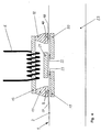
- the figure 1 shows a tube 1 moving in a heating device.
- the tube 1 is made from a sheet wound around a welding rod 23, the edges of the sheet are superposed and welded by heating during their passage through the heating device.
- the wall of the tube 1 consists of at least one metal layer and a layer of thermoplastic material. As indicated above, the presence of a metal layer is necessary to induce heat-generating eddy currents, the latter being used to melt a portion of the thermoplastic layer and thus provide a weld.
- a welding zone 2 extends in the direction of displacement of the tube 1.
- the heating device comprises a first ferromagnetic rod 7, of ferrite for example, incorporated in the welding rod 23 and disposed on the side inside the tube 1, close to the welding zone 2.
- a second 8 and third ferromagnetic rod 10 are disposed above the first bar 7, so that one end of the second bar 8 is in the extension of one end of the first bar 7 and one end of the third bar 10 is in the extension of the other end of the first bar 7.
- the second 8 and the third bar 10 are each surrounded by a coil 3.5.
- the arrangement of the three U-shaped bars 7, 8, 10 makes it possible to obtain an essentially localized heating at the regions 14, 16, the first region 14 being defined between one end of the first bar 7 and one end of the second bar 8, the second region 16 being defined between the other end of the first bar 7 and one end of the third bar 10.
- the distance formed between these two pairs of ends can vary between 2 and 200 times the thickness of the sheet soldering package, and preferably between 2 and 50 times.
- a first heating takes place at the region 14 located between an end of the first bar 7 and an end of the second bar 8. S'en follows a rest period then a new heating at the region 16 located between the other end of the first bar 7 and one end of the third bar 10.
- the devices illustrated on the Figures 2 to 4 are similar to that of the figure 1 . However, they differ in that the set of ferromagnetic elements form a closed loop, the lines of the magnetic field being therefore channeled over all of their loops.
- the second 11 and third ferromagnetic rod 12 are interconnected by means of a fourth bar 13 arranged parallel to the direction of movement of the tube 1.
- the fourth bar is surrounded by a coil 6.
- the coil 6 can also be arranged around the second 11 or the third ferromagnetic bar 12.
- the device illustrated in figure 4 differs only from that of the figure 2 in that the first bar 7 is replaced by a group of 3 bars 19-21 arranged alternately on each side of the wall of the tube 1, the ends of the bars 19-21 superimposed in pairs.
- the welding rods of the state of the art are usually made of a steel core surrounded by a plastic sleeve.
- the welding rod 23 may consist exclusively of a screen material such as copper or aluminum.
- the rod may comprise a steel core 26 surrounded by a plastic sleeve 25 which is itself surrounded by a jacket 24 of copper or aluminum, the ferromagnetic bars (7, 19, 21) being arranged exclusively in the outer casing 24 and in the plastic sleeve 25.
- the copper or aluminum element acts as a screen for the lines of magnetic field.
- the present invention applies to any laminate comprising at least one metal sheet (eg aluminum) and a sheet of thermoplastic material.
Landscapes
- Engineering & Computer Science (AREA)
- Mechanical Engineering (AREA)
- Lining Or Joining Of Plastics Or The Like (AREA)
- Package Closures (AREA)
- General Induction Heating (AREA)
- Containers And Plastic Fillers For Packaging (AREA)
- Basic Packing Technique (AREA)
Description
- La présente invention se rapporte à un dispositif de soudage pour matériau d'emballage en déplacement. Le matériau d'emballage est constitué d'au moins une couche de matière thermoplastique et d'une couche que l'on peut chauffer par induction électromagnétique (p.ex. métallique ou à base de polymère). Le dispositif comprend un générateur de courant alternatif et une bobine pour transformer le courant alternatif en un champ magnétique. Les lignes du champs magnétique sont orientées de manière à traverser le matériau d'emballage, générant ainsi des courants de Foucault dans la couche métallique, la chaleur résultant de ce phénomène est utilisée pour fondre une portion (la zone de soudage) de la couche en matière thermoplastique.
- La demande de brevet français No
2.073.137 - La demande de brevet français No
2 429 657 - La bobine est disposée autour du tube en formation.
- Le brevet américain No
3,242,300 de OHIO CRANKSHAFT COMPANY décrit un inducteur pour le soudage en spirale de tubes. De part et d'autre de la surface à souder sont disposés des éléments de type ferrite afin d'assurer une soudure selon une courbe continue. - Dans les dispositifs de l'état de la technique, les boucles de champ magnétique générées par la bobine ne sont que partiellement canalisées à l'aide d'éléments ferromagnétique. Il en résulte que certaines lignes de champ magnétique traversent le matériau d'emballage en des endroits qui ne correspondent pas à la zone de soudage. Le chauffage de ces régions incontrôlées peut engendrer des déformation dans le matériau d'emballage, p.ex. des ondulations.
- La présente invention a le mérite de remédier notamment au problème précité en offrant un chauffage plus ciblé au niveau de la zone de soudage. Elle concerne un dispositif de soudage d'un matériau d'emballage en déplacement comprenant une couche que l'on peut chauffer par induction électromagnétique (p.ex. métallique ou à base de polymère) et une couche de matière thermoplastique incorporant une zone de soudage qui s'étend selon la direction du déplacement du matériau d'emballage; le dispositif de soudage comprenant un générateur de courant alternatif, une bobine pour transformer le courant alternatif en un champ magnétique, un élément ferromagnétique pour canaliser les lignes du champ magnétique selon une direction déterminée, le champ magnétique étant orienté de manière à traverser le matériau d'emballage pour induire un chauffage de la couche que l'on peut chauffer par induction électromagnétique; le dispositif de soudage étant caractérisé par le fait qu'il comprend un ensemble d'éléments ferromagnétiques qui sont disposés de manière à ce que les lignes de champ magnétique traversent le matériau d'emballage en au moins deux régions distinctes situées le long de la zone de soudage.
- Comme on le verra par la suite, le chauffage localisé en deux régions distinctes est particulièrement avantageux.
- Selon un mode préférentiel de réalisation de l'invention, un premier élément ferromagnétique est disposé d'un côté du matériau d'emballage, par exemple du côté de la face interne de l'emballage en formation. Le premier élément ferromagnétique est disposé de telle manière à ce que ses deux extrémités se trouvent à proximité des deux régions de chauffage. Dans le prolongement des ces extrémités, mais de l'autre côté du matériau d'emballage, se trouve respectivement un deuxième et un troisième élément ferromagnétique dont l'une des extrémités se trouve à proximité des régions de chauffage. Il en résulte que dans l'environnement des régions de chauffage, les lignes de champ magnétique sont canalisées.
- Selon un mode particulièrement avantageux de réalisation de l'invention, le deuxième et le troisième élément ferromagnétique sont reliés entre eux par l'intermédiaire d'un quatrième élément ferromagnétique, une bobine entourant soit le deuxième, soit le troisième ou soit le quatrième élément ferromagnétique, L'ensemble d'élément ainsi réalisé forme un circuit ferromagnétique canalisant de la sorte les boucles de champ magnétique induites par la bobine.
- Il convient de relever que contrairement au dispositif de l'état de la technique décrit dans
US 3,242,300 qui présente une région de chauffage d'étendant sur une courbe, le dispositif selon l'invention vise à chauffer deux régions distinctes. Cette façon de procéder signifie que lors de son déplacement, le matériau d'emballage, au niveau de sa zone de soudage, subira un premier chauffage suivi d'une interruption et d'un deuxième chauffage. - Afin de démontrer l'intérêt d'une zone de "relaxation", on peut comparer deux conceptions de dispositifs de chauffage, la première, telle qu'illustrée dans
US 3,242,300 présente une région de chauffage unique s'étendant sur une longueur L, la deuxième, selon l'invention, présentant une première région (longueur) de chauffage L1, suivie d'une région (longueur) d'interruption L2 et d'une région (longueur) de chauffage L3. - Le premier dispositif est défini par
- L = 60 mm
- On fixe la température de la feuille d'aluminium à 140°C en sortie d'inducteur. Expérimentalement, cela revient à ajuster la puissance fournie à l'inducteur.
- Le deuxième dispositif est défini par
- L1 = 30 mm
- L2 = 30mm
- L3 = 30mm
- La puissance fournie au deuxième dispositif est identique à la puissance fournie au premier dispositif (à vitesse de ligne équivalente)
- La feuille à souder comporte principalement 3 couches
- Polyéthylène/alu/polyéthylène
- 150 microns/12 microns/75 microns
- Plus la vitesse de déplacement est importante, plus il faut fournir l'énergie thermique rapidement. La feuille d'aluminium s'échauffe quasi-instantanément. Par contre, la couche de polymère n'est pas chauffée uniformément dans son épaisseur lorsque la vitesse est élevée (la diffusion thermique dans le polymère est plus lente). La zone transitoire « de relaxation » (L2) permet aux calories de la couche d'aluminium de diffuser dans le polymère et diminuer ainsi le gradient thermique entre les couches d'aluminium et l'interface à souder.
- Quelques exemples non-limitatifs de l'invention sont décrits ci-après au moyen des figures suivantes :
- La
figure 1 illustre une vue de face d'un premier mode de réalisation selon l'invention. - La
figure 2 illustre une vue de face d'un deuxième mode de réalisation selon l'invention. - La
figure 3 illustre une coupe transversale, selon la ligne III-III, du mode de réalisation de lafigure 2 . - La
figure 4 illustre une vue de face d'un troisième mode de réalisation selon l'invention. - La
figure 5 montre une coupe transversale d'une tige de soudage selon un autre mode de réalisation de l'invention. - Chaque élément commun à chaque figure porte la même référence numérique.
- La
figure 1 montre un tube 1 en déplacement dans un dispositif de chauffage. Le tube 1 est réalisé à partir d'une feuille enroulée autour d'une tige de soudage 23, les bords de la feuille sont superposés et soudés par chauffage lors de leur passage à travers le dispositif de chauffage. La paroi du tube 1 est constituée d'au moins une couche métallique et d'une couche en matière thermoplastique. Comme indiqué précédemment, la présence d'une couche métallique est nécessaire pour induire des courants de Foucault générateurs de chaleur, cette dernière étant utilisée pour faire fondre une portion de la couche thermoplastique et assurer ainsi une soudure. - Dans le présent exemple, a zone de soudage 2 s'étend selon la direction de déplacement du tube 1.
- Le dispositif de chauffage comprend un premier barreau ferromagnétique 7, en ferrite par exemple, incorporé dans la tige de soudage 23 et disposé du côté interne du tube 1, à proximité de la zone de soudage 2. Un deuxième 8 et troisième barreau ferromagnétique 10 sont disposés en-dessus du premier barreau 7, de manière à ce qu'une extrémité du deuxième barreau 8 se situe dans le prolongement d'une extrémité du premier barreau 7 et qu'une extrémité du troisième barreau 10 se situe dans le prolongement de l'autre extrémité du premier barreau 7. Le deuxième 8 et le troisième barreau 10 sont chacun entourés d'une bobine 3,5.
- La disposition des trois barreaux 7,8,10, en forme de U, permet d'obtenir un chauffage essentiellement localisé au niveau des régions 14,16, la première région 14 étant définie entre une extrémité du premier barreau 7 et une extrémité du deuxième barreau 8, la deuxième région 16 étant définie entre l'autre extrémité du premier barreau 7 et une extrémité du troisième barreau 10. La distance formée entre ces deux couples d'extrémités peut varier entre 2 et 200 fois l'épaisseur de la feuille d'emballage à souder, et de préférence entre 2 et 50 fois.
- Ainsi, pour un point se situant sur le tube 1 au niveau de sa zone de soudage 2, un premier chauffage a lieu au niveau de la région 14 située entre une extrémité du premier barreau 7 et une extrémité du deuxième barreau 8. S'en suit une période de repos puis une un nouveau chauffage au niveau de la région 16 située entre l'autre extrémité du premier barreau 7 et une extrémité du troisième barreau 10.
- Les dispositifs illustrés sur les
figures 2 à 4 sont similaires à celui de lafigure 1 . Ils diffèrent cependant en ce que l'ensemble des éléments ferromagnétiques forment une boucle fermée, les lignes du champ magnétique étant par conséquent canalisées sur l'ensemble de leurs boucles. - Les deuxième 11 et troisième barreau ferromagnétique 12 sont reliés entre eux par l'intermédiaire d'un quatrième barreau 13 disposé parallèlement à la direction de déplacement du tube 1. Le quatrième barreau est entouré d'une bobine 6.
- La bobine 6 peut également être disposée autour du deuxième 11 ou du troisième barreau ferromagnétique 12.
- Le dispositif illustré à la
figure 4 se différencie uniquement de celui de lafigure 2 en ce que le premier barreau 7 est remplacé par un groupe de 3 barreaux 19-21 disposés alternativement de chaque côté de la paroi du tube 1, les extrémités des barreaux 19-21 se superposant deux à deux. - Les tiges de soudage de l'état de la technique sont le plus souvent constituées d'un noyau en acier entouré d'un manchon en plastique.
- La présence de barreaux ferromagnétiques (7,19,21) dans la tige de soudage 23 permet certes de canaliser la plus grande partie des lignes de champs magnétique à l'intérieur des barreaux.
- Il arrive cependant que certaines lignes de champs se déplacent également dans le manchon en plastique, la performance du chauffage dans les zones de soudage étant par conséquent diminuée.
- Afin de minimiser, voire éliminer, cet inconvénient, la tige de soudage 23 peut être constituée exclusivement d'un matériau formant écran tel que du cuivre ou de l'aluminium.
- Alternativement (voir la
figure 5 ), la tige peut comprendre un noyau d'acier 26 entouré d'un manchon en plastique 25 qui est lui-même entouré d'une enveloppe 24 en cuivre ou en aluminium, les barreaux ferromagnétiques (7,19,21) étant disposés exclusivement dans l'enveloppe externe 24 et dans le manchon en plastique 25. L'effet résultant est le même que dans le cas de figure précédent, à savoir que l'élément en cuivre ou en aluminium joue le rôle d'écran pour les lignes de champs magnétique. - Il convient de relever que la présente invention s'applique à tout laminé comprenant au moins une feuille métallique (p.ex. en aluminium) et une feuille de matière thermoplastique.
- A titre d'exemple non limitatif de laminés pouvant être utilisés, on peut citer les combinaisons suivantes (décrites de l'extérieur vers l'intérieur du tube) :
- 1) Film en polyéthylène (blanc) de 130 microns d'épaisseur- Polyéthylène (blanc) de 27 microns d'épaisseur - Copolymère (blanc) de 16 microns d'épaisseur - Feuille d'aluminium de 12 microns- Copolymer (transparent) de 30 microns d'épaisseur - Film spécial en polyéthylène (transparent) de 60 microns d'épaisseur.
- 2) Polyéthylène (blanc) de 90 microns d'épaisseur - Copolymère (blanc) de 65 microns d'épaisseur - Feuille d'aluminium de 40 microns d'épaisseur - Copolymère (transparent) de 40 microns d'épaisseur - Polyéthylène spécial (transparent) de 75 microns d'épaisseur.
- 3) Polyéthylène (blanc) de 110 microns d'épaisseur - Copolymère (blanc) de 45 microns d'épaisseur - Feuille d'aluminium de 40 microns d'épaisseur - Copolymère (transparent) de 40 microns d'épaisseur - Polyéthylène spécial (Coex) de 75 microns d'épaisseur.
| Vitesse (m/min) | Température (°C) de l'interface à souder à la sortie du premier dispositif | Température (°C) de l'interface à souder à la sortie du deuxième dispositif |
| 20 | 138 | 139 |
| 40 | 126 | 135 |
| 60 | 111 | 124 |
| 80 | 103 | 117 |
Claims (6)
- Dispositif de soudage d'un matériau d'emballage (1) en déplacement comprenant une couche que l'on peut chauffer par induction électromagnétique et une couche de matière thermoplastique incorporant une zone de soudage (2) qui s'étend selon la direction du déplacement du matériau d'emballage; le dispositif de soudage comprenant un générateur de courant alternatif, une bobine (3,5,6) pour transformer le courant alternatif en un champ magnétique, un élément ferromagnétique (7,8,10-13) pour canaliser les lignes du champ magnétique selon une direction déterminée, le champ magnétique étant orienté de manière à traverser le matériau d'emballage (1) pour induire un chauffage de la couche que l'on peut chauffer par induction électromagnétique; le dispositif de soudage étant caractérisé en ce qu'un premier élément ferromagnétique (7) est disposé à proximité d'un côté du matériau d'emballage (1) de manière à ce que chacune de ses extrémités se situe à proximité d'une, respectivement l'autre, des régions distinctes (14,16-18) définies d'une part, entre une extrémité du premier élément ferromagnétique (7) et une extrémité d'un deuxième élément ferromagnétique (8,10-12) et, d'autre part entre l'autre extrémité du premier élément ferromagnétique (7) et une extrémité d'un troisième élément ferromagnétique (8,10-12), et que lesdits deuxième et troisième éléments ferromagnétiques (8,10-12), sont disposés de l'autre côté du matériau d'emballage (1) de façon à ce que l'une des extrémités du deuxième élément (8,10-12) soit située à proximité de l'une desdites régions distinctes (14,16-18) et en ce que l'une des extrémités du troisième élément (8,10-12) soit située à proximité de l'autre desdites régions distinctes (14,16-18), ladite zone de soudage du matériau d'emballage se déplaçant de telle manière qu'elle subit lors de son déplacement un premier chauffage dans une première région distincte suivi d'une interruption dans une région d'interruption et d'un deuxième chauffage dans une deuxième région distincte.
- Dispositif selon la revendication précédente caractérisé par le fait que les extrémités des trois éléments ferromagnétiques (7,8,10) disposées à proximité et de part et d'autre de la couche à souder sont séparées d'une distance représentant entre 2 et 200 fois, de préférence entre 2 et 50 fois, l'épaisseur de la couche à souder.
- Dispositif selon la revendication 1 ou 2 caractérisé par le fait que le deuxième (8,10-12) et le troisième élément ferromagnétique (8,10-12) sont entourés d'une bobine (3,5,6).
- Dispositif selon l'une quelconque des revendications précédentes caractérisé par le fait que l'ensemble des éléments ferromagnétiques (7,8,10,11, 19-21) forme un circuit ferromagnétique, une bobine (6) entourant un élément ferromagnétique (7,8,10,11,19-21).
- Dispositif selon l'une quelconque des revendications précédentes caractérisé par le fait qu'il comprend un ou plusieurs écrans magnétiques disposé entre des éléments ferromagnétiques (7,8,10,11,19-21) non-adjacents.
- Dispositif selon l'une quelconque des revendications précédentes caractérisé par le fait qu'une partie des barreaux ferromagnétiques (7,19,21) est disposé dans une tige de soudage 23, cette dernière comprenant un élément écran, par exemple en cuivre ou en aluminium, disposé de manière à confiner les lignes de champs dans les barreaux ferromagnétiques (7,19,21).
Applications Claiming Priority (3)
| Application Number | Priority Date | Filing Date | Title |
|---|---|---|---|
| CH23552001 | 2001-12-20 | ||
| CH23552001 | 2001-12-20 | ||
| PCT/CH2002/000699 WO2003053626A2 (fr) | 2001-12-20 | 2002-12-16 | Dispositif de soudage pour materiau d'emballage |
Publications (2)
| Publication Number | Publication Date |
|---|---|
| EP1458514A2 EP1458514A2 (fr) | 2004-09-22 |
| EP1458514B1 true EP1458514B1 (fr) | 2008-10-08 |
Family
ID=4568752
Family Applications (1)
| Application Number | Title | Priority Date | Filing Date |
|---|---|---|---|
| EP02782610A Expired - Lifetime EP1458514B1 (fr) | 2001-12-20 | 2002-12-16 | Dispositif de soudage pour materiau d'emballage |
Country Status (16)
| Country | Link |
|---|---|
| US (1) | US7002117B2 (fr) |
| EP (1) | EP1458514B1 (fr) |
| JP (1) | JP4510460B2 (fr) |
| KR (1) | KR20040071735A (fr) |
| CN (1) | CN1309525C (fr) |
| AT (1) | ATE410259T1 (fr) |
| AU (1) | AU2002347188B2 (fr) |
| BR (1) | BR0215165B1 (fr) |
| CA (1) | CA2470077A1 (fr) |
| DE (2) | DE60229294D1 (fr) |
| ES (1) | ES2228295T1 (fr) |
| HK (1) | HK1075862A1 (fr) |
| MX (1) | MXPA04005916A (fr) |
| RU (1) | RU2301730C2 (fr) |
| TR (1) | TR200403719T3 (fr) |
| WO (1) | WO2003053626A2 (fr) |
Families Citing this family (17)
| Publication number | Priority date | Publication date | Assignee | Title |
|---|---|---|---|---|
| JP2010160142A (ja) * | 2008-12-09 | 2010-07-22 | Renesas Electronics Corp | 信号送受信方法、半導体装置の製造方法、半導体装置、およびテスタ装置 |
| US8758544B2 (en) | 2010-10-29 | 2014-06-24 | Pilkington Group Limited | Method and apparatus for forming a vehicle window assembly |
| JP5969599B2 (ja) * | 2012-08-17 | 2016-08-17 | 新日鐵住金株式会社 | 電縫管溶接装置 |
| WO2014027565A1 (fr) * | 2012-08-17 | 2014-02-20 | 新日鐵住金株式会社 | Dispositif de soudage destiné à un tuyau soudé par résistance électrique |
| EP3154767B1 (fr) | 2014-06-12 | 2019-11-20 | Tetra Laval Holdings & Finance SA | Dispositif de chauffage par induction |
| CN108290351B (zh) | 2015-11-27 | 2020-09-22 | 利乐拉瓦尔集团及财务有限公司 | 具有增强的稳固性的密封装置 |
| EP3241667B1 (fr) | 2016-05-02 | 2020-07-08 | Tetra Laval Holdings & Finance S.A. | Système de scellage par induction amélioré |
| RU2759707C2 (ru) | 2017-05-30 | 2021-11-17 | Тетра Лаваль Холдингз Энд Файнэнс С.А. | Устройство для запечатывания верха упаковки для пищевого продукта и система для формирования и заполнения упаковки с пищевым продуктом |
| BR112019025761B1 (pt) * | 2017-07-17 | 2023-12-26 | Tetra Laval Holdings & Finance S.A. | Bobina indutora para soldagem, dispositivo e máquina de vedação, e, método para fabricação de bobina indutora |
| JP2020527519A (ja) | 2017-07-18 | 2020-09-10 | テトラ ラバル ホールディングス アンド ファイナンス エス エイ | 誘導シール装置 |
| DE102018203904A1 (de) | 2018-03-14 | 2019-09-19 | Robert Bosch Gmbh | Vorrichtung zum Siegeln einer Verpackung |
| CN108639456A (zh) * | 2018-04-23 | 2018-10-12 | 佛山市奥耶克思机械设备有限公司 | 包装机的电磁感应热封装置 |
| RU184919U1 (ru) * | 2018-06-13 | 2018-11-14 | Федеральное государственное бюджетное учреждение науки Институт проблем нефти и газа Сибирского отделения Российской академии наук | Устройство для сварки сверхвысокомолекулярного полиэтилена |
| CN109263052B (zh) * | 2018-09-03 | 2021-02-09 | 马鞍山市鑫程纳米新材料科技有限公司 | 一种塑料薄膜热合机 |
| CN112672875B (zh) | 2018-09-10 | 2023-03-28 | 利乐拉瓦尔集团及财务有限公司 | 用于形成管的方法以及用于形成包装的方法和包装机 |
| EP3623301B1 (fr) | 2018-09-11 | 2021-07-14 | Tetra Laval Holdings & Finance S.A. | Appareil d'emballage pour former des emballages scellés |
| CN113579450B (zh) * | 2021-07-07 | 2023-03-24 | 宁波微鹅电子科技有限公司 | 一种电磁焊接结构 |
Family Cites Families (13)
| Publication number | Priority date | Publication date | Assignee | Title |
|---|---|---|---|---|
| US2632079A (en) * | 1950-11-30 | 1953-03-17 | Ohio Crankshaft Co | Means and method for electric seam welding |
| US3248512A (en) * | 1963-12-19 | 1966-04-26 | Ohio Crankshaft Co | Apparatus for welding metal tubing |
| US3406271A (en) * | 1964-05-15 | 1968-10-15 | Park Ohio Industries Inc | Impedor for a tube mill |
| SE346251B (fr) * | 1969-12-10 | 1972-07-03 | Tetra Pak Int | |
| GB1327280A (en) | 1969-12-10 | 1973-08-22 | Tetra Pak Int | Method of and means for sealing packaging material |
| JPS5934501B2 (ja) * | 1975-08-06 | 1984-08-23 | 東洋製罐株式会社 | 袋状容器の製造方法およびその装置 |
| JPS531614A (en) * | 1976-06-26 | 1978-01-09 | Toyo Alum Kk | Induction heating equipment |
| US4210477A (en) | 1978-06-30 | 1980-07-01 | American Can Company | Tube forming method |
| US4694134A (en) * | 1985-05-28 | 1987-09-15 | Ajax Magnethermic Corporation | Apparatus for overheating edges of skelp for the production of compression welded pipe |
| US5444220A (en) * | 1991-10-18 | 1995-08-22 | The Boeing Company | Asymmetric induction work coil for thermoplastic welding |
| US5571437A (en) * | 1995-06-05 | 1996-11-05 | Thermatool Corp. | Induction welding of tubing with multiple induction coils |
| DE69704132T2 (de) * | 1996-06-11 | 2001-06-21 | Kawasaki Steel Co | Verfahren und Vorrichtung zur Herstellung von Stahlrohren |
| CN1289222C (zh) * | 2001-07-13 | 2006-12-13 | 昌德机电(天津)有限公司 | 金属壳制造方法 |
-
2002
- 2002-12-16 WO PCT/CH2002/000699 patent/WO2003053626A2/fr active Application Filing
- 2002-12-16 EP EP02782610A patent/EP1458514B1/fr not_active Expired - Lifetime
- 2002-12-16 MX MXPA04005916A patent/MXPA04005916A/es active IP Right Grant
- 2002-12-16 AT AT02782610T patent/ATE410259T1/de not_active IP Right Cessation
- 2002-12-16 ES ES02782610T patent/ES2228295T1/es active Pending
- 2002-12-16 KR KR20047009530A patent/KR20040071735A/ko not_active Application Discontinuation
- 2002-12-16 AU AU2002347188A patent/AU2002347188B2/en not_active Ceased
- 2002-12-16 BR BRPI0215165-0B1A patent/BR0215165B1/pt not_active IP Right Cessation
- 2002-12-16 DE DE60229294T patent/DE60229294D1/de not_active Expired - Lifetime
- 2002-12-16 JP JP2003554377A patent/JP4510460B2/ja not_active Expired - Fee Related
- 2002-12-16 CA CA002470077A patent/CA2470077A1/fr not_active Abandoned
- 2002-12-16 TR TR2004/03719T patent/TR200403719T3/xx unknown
- 2002-12-16 CN CNB028254759A patent/CN1309525C/zh not_active Expired - Fee Related
- 2002-12-16 US US10/498,907 patent/US7002117B2/en not_active Expired - Lifetime
- 2002-12-16 DE DE02782610T patent/DE02782610T1/de active Pending
- 2002-12-16 RU RU2004122099/02A patent/RU2301730C2/ru not_active IP Right Cessation
-
2005
- 2005-09-07 HK HK05107828A patent/HK1075862A1/xx not_active IP Right Cessation
Also Published As
| Publication number | Publication date |
|---|---|
| AU2002347188A1 (en) | 2003-07-09 |
| DE02782610T1 (de) | 2005-05-04 |
| US20050133496A1 (en) | 2005-06-23 |
| TR200403719T3 (tr) | 2005-08-22 |
| RU2301730C2 (ru) | 2007-06-27 |
| JP2005512847A (ja) | 2005-05-12 |
| WO2003053626A3 (fr) | 2004-02-26 |
| HK1075862A1 (en) | 2005-12-30 |
| CN1309525C (zh) | 2007-04-11 |
| BR0215165B1 (pt) | 2013-09-03 |
| WO2003053626A2 (fr) | 2003-07-03 |
| DE60229294D1 (de) | 2008-11-20 |
| CN1606484A (zh) | 2005-04-13 |
| KR20040071735A (ko) | 2004-08-12 |
| ATE410259T1 (de) | 2008-10-15 |
| US7002117B2 (en) | 2006-02-21 |
| BR0215165A (pt) | 2004-10-19 |
| EP1458514A2 (fr) | 2004-09-22 |
| MXPA04005916A (es) | 2005-05-16 |
| RU2004122099A (ru) | 2005-03-27 |
| JP4510460B2 (ja) | 2010-07-21 |
| ES2228295T1 (es) | 2005-04-16 |
| CA2470077A1 (fr) | 2003-07-03 |
| AU2002347188B2 (en) | 2008-04-03 |
Similar Documents
| Publication | Publication Date | Title |
|---|---|---|
| EP1458514B1 (fr) | Dispositif de soudage pour materiau d'emballage | |
| CA2620883C (fr) | Dispositif de transformation de materiaux utilisant un chauffage par induction | |
| EP0430761B1 (fr) | Procédé et pièce de raccordement utilisant une résistance électrique pour le soudage d'éléments en matière plastique | |
| EP1817942B1 (fr) | Procede et dispositif pour braser des raccords par chauffage inductif | |
| EP1145842A2 (fr) | Vitre feuilletée | |
| FR2809528A1 (fr) | Cable coaxial flexible et procede de fabrication de celui-ci | |
| EP1905570A1 (fr) | Procédé et dispositif de soudage intérieur de tubes en matière plastique | |
| EP0462011A1 (fr) | Bobine de chauffage inductif | |
| EP1148762A1 (fr) | Dispositif de chauffage par induction à flux transverse à circuit magnétique de largeur variable | |
| EP2022293B1 (fr) | Element metallique dissipant une énergie thermique, traversé par un flux d'air et par un courant électrique | |
| EP0916144A1 (fr) | Procede de fabrication de bobine pour transpondeurs et transpondeur fabrique selon ce procede | |
| EP2459360B1 (fr) | Procédé et dispositif pour souder un emballage plastique tubulaire et emballage ainsi obtenu | |
| FR2463492A1 (fr) | Transformateur ou bobine | |
| FR2468194A1 (fr) | Bobinage electrique destine par exemple a un transformateur ou a une bobine d'inductance | |
| EP1774567A2 (fr) | Lampe a barrieres de decharge | |
| EP1849581A1 (fr) | Dispositif de soudage par induction magnétique | |
| WO2003097332A1 (fr) | Dispositif de soudage pour materiau d'emballage | |
| FR2972890A1 (fr) | Systeme inductif pouvant servir de creuset froid | |
| WO2023104911A1 (fr) | Element d'un equipement de chauffage par induction apte a recevoir un fluide de refroidissement | |
| FR2685602A3 (en) | Electric heater for instantaneously heating water | |
| FR2764788A1 (fr) | Dispositif de chauffage de liquides, notamment pour une machine a cafe | |
| FR2631427A1 (fr) | Element chauffant pour un radiateur electrique utilise pour le chauffage de locaux, notamment de type continu | |
| JP2015176812A (ja) | 誘導加熱発熱体の製造装置及び製造方法 | |
| FR2642566A1 (fr) | Transformateur annulaire | |
| FR2679486A1 (fr) | Dispositif pour le soudage de matieres plastiques. |
Legal Events
| Date | Code | Title | Description |
|---|---|---|---|
| PUAI | Public reference made under article 153(3) epc to a published international application that has entered the european phase |
Free format text: ORIGINAL CODE: 0009012 |
|
| 17P | Request for examination filed |
Effective date: 20040623 |
|
| AK | Designated contracting states |
Kind code of ref document: A2 Designated state(s): AT BE BG CH CY CZ DE DK EE ES FI FR GB GR IE IT LI LU MC NL PT SE SI SK TR |
|
| AX | Request for extension of the european patent |
Extension state: AL LT LV MK RO |
|
| REG | Reference to a national code |
Ref country code: SE Ref legal event code: TRCL |
|
| GBC | Gb: translation of claims filed (gb section 78(7)/1977) | ||
| REG | Reference to a national code |
Ref country code: GR Ref legal event code: PP Ref document number: 20040300040 Country of ref document: GR |
|
| TCAT | At: translation of patent claims filed | ||
| TCNL | Nl: translation of patent claims filed | ||
| REG | Reference to a national code |
Ref country code: EE Ref legal event code: BB2E |
|
| DET | De: translation of patent claims | ||
| 17Q | First examination report despatched |
Effective date: 20050420 |
|
| GRAC | Information related to communication of intention to grant a patent modified |
Free format text: ORIGINAL CODE: EPIDOSCIGR1 |
|
| GRAP | Despatch of communication of intention to grant a patent |
Free format text: ORIGINAL CODE: EPIDOSNIGR1 |
|
| GRAS | Grant fee paid |
Free format text: ORIGINAL CODE: EPIDOSNIGR3 |
|
| GRAA | (expected) grant |
Free format text: ORIGINAL CODE: 0009210 |
|
| AK | Designated contracting states |
Kind code of ref document: B1 Designated state(s): AT BE BG CH CY CZ DE DK EE ES FI FR GB GR IE IT LI LU MC NL PT SE SI SK TR |
|
| REG | Reference to a national code |
Ref country code: GB Ref legal event code: FG4D Free format text: NOT ENGLISH |
|
| REG | Reference to a national code |
Ref country code: CH Ref legal event code: EP |
|
| REG | Reference to a national code |
Ref country code: IE Ref legal event code: FG4D Free format text: LANGUAGE OF EP DOCUMENT: FRENCH |
|
| REF | Corresponds to: |
Ref document number: 60229294 Country of ref document: DE Date of ref document: 20081120 Kind code of ref document: P |
|
| REG | Reference to a national code |
Ref country code: CH Ref legal event code: NV Representative=s name: ANDRE ROLAND S.A. |
|
| PG25 | Lapsed in a contracting state [announced via postgrant information from national office to epo] |
Ref country code: SI Free format text: LAPSE BECAUSE OF FAILURE TO SUBMIT A TRANSLATION OF THE DESCRIPTION OR TO PAY THE FEE WITHIN THE PRESCRIBED TIME-LIMIT Effective date: 20081008 |
|
| NLV1 | Nl: lapsed or annulled due to failure to fulfill the requirements of art. 29p and 29m of the patents act | ||
| PG25 | Lapsed in a contracting state [announced via postgrant information from national office to epo] |
Ref country code: ES Free format text: LAPSE BECAUSE OF FAILURE TO SUBMIT A TRANSLATION OF THE DESCRIPTION OR TO PAY THE FEE WITHIN THE PRESCRIBED TIME-LIMIT Effective date: 20090119 Ref country code: AT Free format text: LAPSE BECAUSE OF FAILURE TO SUBMIT A TRANSLATION OF THE DESCRIPTION OR TO PAY THE FEE WITHIN THE PRESCRIBED TIME-LIMIT Effective date: 20081008 |
|
| PG25 | Lapsed in a contracting state [announced via postgrant information from national office to epo] |
Ref country code: PT Free format text: LAPSE BECAUSE OF FAILURE TO SUBMIT A TRANSLATION OF THE DESCRIPTION OR TO PAY THE FEE WITHIN THE PRESCRIBED TIME-LIMIT Effective date: 20090218 Ref country code: FI Free format text: LAPSE BECAUSE OF FAILURE TO SUBMIT A TRANSLATION OF THE DESCRIPTION OR TO PAY THE FEE WITHIN THE PRESCRIBED TIME-LIMIT Effective date: 20081008 Ref country code: NL Free format text: LAPSE BECAUSE OF FAILURE TO SUBMIT A TRANSLATION OF THE DESCRIPTION OR TO PAY THE FEE WITHIN THE PRESCRIBED TIME-LIMIT Effective date: 20081008 |
|
| BERE | Be: lapsed |
Owner name: AISAPACK HOLDING SA Effective date: 20081231 |
|
| REG | Reference to a national code |
Ref country code: IE Ref legal event code: FD4D |
|
| PG25 | Lapsed in a contracting state [announced via postgrant information from national office to epo] |
Ref country code: IE Free format text: LAPSE BECAUSE OF FAILURE TO SUBMIT A TRANSLATION OF THE DESCRIPTION OR TO PAY THE FEE WITHIN THE PRESCRIBED TIME-LIMIT Effective date: 20081008 Ref country code: EE Free format text: LAPSE BECAUSE OF FAILURE TO SUBMIT A TRANSLATION OF THE DESCRIPTION OR TO PAY THE FEE WITHIN THE PRESCRIBED TIME-LIMIT Effective date: 20081008 Ref country code: DK Free format text: LAPSE BECAUSE OF FAILURE TO SUBMIT A TRANSLATION OF THE DESCRIPTION OR TO PAY THE FEE WITHIN THE PRESCRIBED TIME-LIMIT Effective date: 20081008 Ref country code: MC Free format text: LAPSE BECAUSE OF NON-PAYMENT OF DUE FEES Effective date: 20081231 |
|
| PLBE | No opposition filed within time limit |
Free format text: ORIGINAL CODE: 0009261 |
|
| STAA | Information on the status of an ep patent application or granted ep patent |
Free format text: STATUS: NO OPPOSITION FILED WITHIN TIME LIMIT |
|
| PG25 | Lapsed in a contracting state [announced via postgrant information from national office to epo] |
Ref country code: SE Free format text: LAPSE BECAUSE OF FAILURE TO SUBMIT A TRANSLATION OF THE DESCRIPTION OR TO PAY THE FEE WITHIN THE PRESCRIBED TIME-LIMIT Effective date: 20090108 Ref country code: CZ Free format text: LAPSE BECAUSE OF FAILURE TO SUBMIT A TRANSLATION OF THE DESCRIPTION OR TO PAY THE FEE WITHIN THE PRESCRIBED TIME-LIMIT Effective date: 20081008 |
|
| 26N | No opposition filed |
Effective date: 20090709 |
|
| PG25 | Lapsed in a contracting state [announced via postgrant information from national office to epo] |
Ref country code: BE Free format text: LAPSE BECAUSE OF NON-PAYMENT OF DUE FEES Effective date: 20081231 |
|
| PG25 | Lapsed in a contracting state [announced via postgrant information from national office to epo] |
Ref country code: SK Free format text: LAPSE BECAUSE OF NON-PAYMENT OF DUE FEES Effective date: 20081216 |
|
| PG25 | Lapsed in a contracting state [announced via postgrant information from national office to epo] |
Ref country code: LU Free format text: LAPSE BECAUSE OF NON-PAYMENT OF DUE FEES Effective date: 20081216 |
|
| PG25 | Lapsed in a contracting state [announced via postgrant information from national office to epo] |
Ref country code: TR Free format text: LAPSE BECAUSE OF FAILURE TO SUBMIT A TRANSLATION OF THE DESCRIPTION OR TO PAY THE FEE WITHIN THE PRESCRIBED TIME-LIMIT Effective date: 20081008 |
|
| PG25 | Lapsed in a contracting state [announced via postgrant information from national office to epo] |
Ref country code: GR Free format text: LAPSE BECAUSE OF FAILURE TO SUBMIT A TRANSLATION OF THE DESCRIPTION OR TO PAY THE FEE WITHIN THE PRESCRIBED TIME-LIMIT Effective date: 20090109 |
|
| PG25 | Lapsed in a contracting state [announced via postgrant information from national office to epo] |
Ref country code: CY Free format text: LAPSE BECAUSE OF FAILURE TO SUBMIT A TRANSLATION OF THE DESCRIPTION OR TO PAY THE FEE WITHIN THE PRESCRIBED TIME-LIMIT Effective date: 20081008 |
|
| REG | Reference to a national code |
Ref country code: CH Ref legal event code: PCAR Free format text: ANDRE ROLAND S.A.;CASE POSTALE 5107;1002 LAUSANNE (CH) |
|
| PGFP | Annual fee paid to national office [announced via postgrant information from national office to epo] |
Ref country code: GB Payment date: 20131219 Year of fee payment: 12 Ref country code: DE Payment date: 20131220 Year of fee payment: 12 |
|
| PGFP | Annual fee paid to national office [announced via postgrant information from national office to epo] |
Ref country code: IT Payment date: 20131220 Year of fee payment: 12 |
|
| PGFP | Annual fee paid to national office [announced via postgrant information from national office to epo] |
Ref country code: FR Payment date: 20131220 Year of fee payment: 12 |
|
| REG | Reference to a national code |
Ref country code: DE Ref legal event code: R119 Ref document number: 60229294 Country of ref document: DE |
|
| GBPC | Gb: european patent ceased through non-payment of renewal fee |
Effective date: 20141216 |
|
| REG | Reference to a national code |
Ref country code: FR Ref legal event code: ST Effective date: 20150831 |
|
| PG25 | Lapsed in a contracting state [announced via postgrant information from national office to epo] |
Ref country code: DE Free format text: LAPSE BECAUSE OF NON-PAYMENT OF DUE FEES Effective date: 20150701 Ref country code: GB Free format text: LAPSE BECAUSE OF NON-PAYMENT OF DUE FEES Effective date: 20141216 |
|
| PG25 | Lapsed in a contracting state [announced via postgrant information from national office to epo] |
Ref country code: FR Free format text: LAPSE BECAUSE OF NON-PAYMENT OF DUE FEES Effective date: 20141231 |
|
| PG25 | Lapsed in a contracting state [announced via postgrant information from national office to epo] |
Ref country code: IT Free format text: LAPSE BECAUSE OF NON-PAYMENT OF DUE FEES Effective date: 20141216 |
|
| PGFP | Annual fee paid to national office [announced via postgrant information from national office to epo] |
Ref country code: BG Payment date: 20181220 Year of fee payment: 17 Ref country code: CH Payment date: 20181218 Year of fee payment: 17 |
|
| REG | Reference to a national code |
Ref country code: CH Ref legal event code: PL |
|
| PG25 | Lapsed in a contracting state [announced via postgrant information from national office to epo] |
Ref country code: CH Free format text: LAPSE BECAUSE OF NON-PAYMENT OF DUE FEES Effective date: 20191231 Ref country code: LI Free format text: LAPSE BECAUSE OF NON-PAYMENT OF DUE FEES Effective date: 20191231 Ref country code: BG Free format text: LAPSE BECAUSE OF NON-PAYMENT OF DUE FEES Effective date: 20200630 |