EP1457759A1 - Abdeckgewebe für Anzündstoffe in pyrotechnischen Anzündern - Google Patents
Abdeckgewebe für Anzündstoffe in pyrotechnischen Anzündern Download PDFInfo
- Publication number
- EP1457759A1 EP1457759A1 EP04005003A EP04005003A EP1457759A1 EP 1457759 A1 EP1457759 A1 EP 1457759A1 EP 04005003 A EP04005003 A EP 04005003A EP 04005003 A EP04005003 A EP 04005003A EP 1457759 A1 EP1457759 A1 EP 1457759A1
- Authority
- EP
- European Patent Office
- Prior art keywords
- igniter
- fabric
- pyrotechnic
- circonium
- absorbent
- Prior art date
- Legal status (The legal status is an assumption and is not a legal conclusion. Google has not performed a legal analysis and makes no representation as to the accuracy of the status listed.)
- Granted
Links
Images


Classifications
-
- F—MECHANICAL ENGINEERING; LIGHTING; HEATING; WEAPONS; BLASTING
- F42—AMMUNITION; BLASTING
- F42B—EXPLOSIVE CHARGES, e.g. FOR BLASTING, FIREWORKS, AMMUNITION
- F42B3/00—Blasting cartridges, i.e. case and explosive
- F42B3/10—Initiators therefor
- F42B3/195—Manufacture
-
- F—MECHANICAL ENGINEERING; LIGHTING; HEATING; WEAPONS; BLASTING
- F42—AMMUNITION; BLASTING
- F42B—EXPLOSIVE CHARGES, e.g. FOR BLASTING, FIREWORKS, AMMUNITION
- F42B3/00—Blasting cartridges, i.e. case and explosive
- F42B3/10—Initiators therefor
- F42B3/12—Bridge initiators
- F42B3/124—Bridge initiators characterised by the configuration or material of the bridge
Definitions
- the invention relates to pyrotechnic igniters according to the preamble of the claim 1, a method of manufacturing these lighters and their use.
- the functional reliability of an electric lighter depends to a great extent on that thermal-mechanical coupling between the ignition resistor, which is called wire or can be designed as a sheet-like thin film resistor, and the applied igniter.
- thermal-mechanical coupling between the ignition resistor which is called wire or can be designed as a sheet-like thin film resistor, and the applied igniter.
- the primers become moist or pasty provided with binders, but also for technical reasons, because these initial igniters are dry to handle in large quantities, d. H. they can explode if rubbed. In mass production therefore great efforts are made to place the detonators before placing them they are usually in even larger containers for handling by mixing to be as insensitive as possible to solvents or water.
- the object of the invention is therefore to find a way of creating To prevent gas bubbles and at the same time to achieve further technical advantages.
- This object is related to a method of manufacturing a pyrotechnic Igniter according to the preamble of claim 1 solved in that after Apply the wet kindling and a sieve-like one before drying absorbent cover fabric pressed into the viscous kindling becomes.
- a pyrotechnic igniter according to the preamble of claim 1 stands out according to the invention in that on the ignition resistor a sieve-like absorbent cover fabric is arranged, in which at least part of the igniter located.
- the cover fabric consists of reactive fibers such as z. B. nitrocellulose threads, Circonium thread, Circonium wool or coated Plastic threads with pigments made of aluminum powder or circonium powder.
- the cover fabric is a felt-like absorbent Press fabrics.
- pyrotechnic igniters are preferably used in automotive occupant protection technology such as B. airbags or belt tensioners.
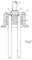
- FIGS. 1 and 2 shown by introducing pasty igniter 5.
- the igniter 5 is considered Grafting introduced by various possible methods, here z. B. with a Injection tube 6. This element is then loaded in a continuous furnace or dried in a solvent concentration controlled oven. If a gas bubble 7 arises and it is of all places on the ignition resistor 4 the likelihood of a later failure is extremely high (Fig. 2).
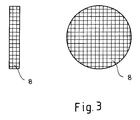
- FIG. 3 shows this cover fabric designed as a construction element.
- This cover fabric 8 can be made of very different materials being constructed.
- An aid to the chemical reaction during ignition Effect can, for. B. by used for the tissue reactive fiber materials such as Aluminum filaments, nitrocellulose threads etc. can be achieved.
- it can also felt-like press fabric can be used, which consists of absorbent materials.
- fiber filaments can be coated with reactive substances and the like be used.
- a cover fabric 8 (here formed as a disc), so it turns out due to the capillary effects resulting from the cavities and the property of the Ignition result in a high adhesive force.
- the sieve-like fabric disc 8 pulls with high adhesive force on the surface of the ignition resistor 4.
- the entire reactive area can be significant are better defined than by a statistically random one Drops.
- a thin film of kindling that can be achieved by design would like to be able to train in a very defined way with this fabric element.
- the capillary forces that develop are adjusted with a suitable adjustment of the fiber texture a highly adherent, thin, well-defined detonating film on the Ignition resistance enables.
Landscapes
- Engineering & Computer Science (AREA)
- General Engineering & Computer Science (AREA)
- Manufacturing & Machinery (AREA)
- Air Bags (AREA)
- Lighters Containing Fuel (AREA)
- Woven Fabrics (AREA)
Abstract
Description
Claims (5)
- Verfahren zur Herstellung eines pyrotechnischen Anzünders mit einem Gehäuse (1) in dem ein elektrischer Zündwiderstand (4) angeordnet ist, auf den ein nasser Anzündstoff (5) aufgebracht wird und anschließend dieser Anzündstoff (5) einem Trocknungsvorgang unterzogen wird, dadurch gekennzeichnet, dass nach Aufbringen des nassen Anzündstoffes (5) und vor dem Trocknungsvorgang ein siebähnliches saugfähiges Abdeckgewebe (8) in den noch zähflüssigen Anzündstoff (5) gedrückt wird.
- Pyrotechnischer Anzünder mit einem Gehäuse (1) in dem ein elektrischer Zündwiderstand (4) angeordnet ist, auf dem sich ein Anzündstoff (5) befindet, dadurch gekennzeichnet, dass auf dem Zündwiderstand (4) ein siebähnliches saugfähiges Abdeckgewebe (8) angeordnet ist, in dem sich zumindest ein Teil des Anzündstoffes (5) befindet.
- Anzünder nach Anspruch 2, dadurch gekennzeichnet, dass das Abdeckgewebe (8) aus reaktiven Fasern besteht, wie z. B. Nitrozellulosefäden, Circonium-Fäden, Circonium-Wolle oder beschichteten Kunststofffäden mit Pigmenten aus Aluminiumpulver oder Circoniumpulver.
- Anzünder nach Anspruch 2, dadurch gekennzeichnet, dass das Abdeckgewebe (8) ein filzähnliches saugfähiges Pressgewebe ist.
- Verwendung eines pyrotechnischen Anzünders nach einem der Ansprüche 2 bis 4 oder nach dem Verfahren gemäß Anspruch 1 für die Automobilinsassenschutztechnik wie z. B. Airbags oder Gurtstraffer.
Applications Claiming Priority (4)
| Application Number | Priority Date | Filing Date | Title |
|---|---|---|---|
| DE10004749 | 2000-02-03 | ||
| DE10310177 | 2003-03-08 | ||
| DE10310177 | 2003-03-08 | ||
| DE102004004749A DE102004004749A1 (de) | 2003-03-08 | 2004-01-30 | Abdeckgewebe für Anzündstoffe in pyrotechnischen Anzündern |
Publications (2)
| Publication Number | Publication Date |
|---|---|
| EP1457759A1 true EP1457759A1 (de) | 2004-09-15 |
| EP1457759B1 EP1457759B1 (de) | 2007-05-16 |
Family
ID=37908161
Family Applications (1)
| Application Number | Title | Priority Date | Filing Date |
|---|---|---|---|
| EP04005003A Expired - Lifetime EP1457759B1 (de) | 2003-03-08 | 2004-03-03 | Abdeckgewebe für Anzündstoffe in pyrotechnischen Anzündern |
Country Status (3)
| Country | Link |
|---|---|
| EP (1) | EP1457759B1 (de) |
| AT (1) | ATE362607T1 (de) |
| DE (2) | DE102004004749A1 (de) |
Cited By (1)
| Publication number | Priority date | Publication date | Assignee | Title |
|---|---|---|---|---|
| WO2007062200A3 (en) * | 2005-11-25 | 2007-10-11 | Tk Holdings Inc | Gas generator |
Citations (3)
| Publication number | Priority date | Publication date | Assignee | Title |
|---|---|---|---|---|
| FR2599361A1 (fr) * | 1986-05-27 | 1987-12-04 | Survilliers Nle Cartoucherie | Composition pyrotechnique pour inflammateur et allumeur electrique de securite, inflammateur et allumeur ainsi obtenus |
| US6007096A (en) * | 1998-04-20 | 1999-12-28 | Trw Inc. | Inflator having a pressure monitoring initiator |
| US20020174791A1 (en) * | 2000-12-08 | 2002-11-28 | Vahan Avetisian | Initiator with an internal sleeve retaining a pyrotechnic charge and methods of making same |
-
2004
- 2004-01-30 DE DE102004004749A patent/DE102004004749A1/de not_active Withdrawn
- 2004-03-03 EP EP04005003A patent/EP1457759B1/de not_active Expired - Lifetime
- 2004-03-03 DE DE502004003815T patent/DE502004003815D1/de not_active Expired - Lifetime
- 2004-03-03 AT AT04005003T patent/ATE362607T1/de active
Patent Citations (3)
| Publication number | Priority date | Publication date | Assignee | Title |
|---|---|---|---|---|
| FR2599361A1 (fr) * | 1986-05-27 | 1987-12-04 | Survilliers Nle Cartoucherie | Composition pyrotechnique pour inflammateur et allumeur electrique de securite, inflammateur et allumeur ainsi obtenus |
| US6007096A (en) * | 1998-04-20 | 1999-12-28 | Trw Inc. | Inflator having a pressure monitoring initiator |
| US20020174791A1 (en) * | 2000-12-08 | 2002-11-28 | Vahan Avetisian | Initiator with an internal sleeve retaining a pyrotechnic charge and methods of making same |
Cited By (2)
| Publication number | Priority date | Publication date | Assignee | Title |
|---|---|---|---|---|
| WO2007062200A3 (en) * | 2005-11-25 | 2007-10-11 | Tk Holdings Inc | Gas generator |
| US9027965B2 (en) | 2005-11-25 | 2015-05-12 | Tk Holdings Inc. | Gas generator |
Also Published As
| Publication number | Publication date |
|---|---|
| ATE362607T1 (de) | 2007-06-15 |
| EP1457759B1 (de) | 2007-05-16 |
| DE102004004749A1 (de) | 2004-11-18 |
| DE502004003815D1 (de) | 2007-06-28 |
Similar Documents
| Publication | Publication Date | Title |
|---|---|---|
| EP0718591B1 (de) | Anzündsystem für Treibladungen und Verfahren zur Herstellung derartiger Anzündsysteme | |
| DE2136750C3 (de) | ||
| DE2428632C3 (de) | Verfahren zum Herstellen von brennbaren Munitionsformteilen und Vorrichtung zur Durchführung des Verfahrens | |
| DE3114933C2 (de) | ||
| DE1526829C1 (de) | Verfahren zur Herstellung von doppelbasigen Festtreibstoffen | |
| DE2206468C2 (de) | Elektrische Zündung | |
| EP0322951B1 (de) | Vorrichtung zur raschen Erzeugung von künstlichem Nebel und Verfahren zur Herstellung von Nebelsätzen | |
| DE1912727C3 (de) | Verfahren zur Oberflachenbehandlung von aus brennbaren Werkstoffen bestehenden Munitionshulsen und hiernach hergestellte Munitionshülsen bzw. Kartuschen | |
| EP1457759B1 (de) | Abdeckgewebe für Anzündstoffe in pyrotechnischen Anzündern | |
| DE1590867A1 (de) | Verfahren zur Herstellung von Widerstandselementen | |
| DE1807315A1 (de) | Unpatronierte geformte Schiess- bzw.Sprengstoffe | |
| DE1909701A1 (de) | Brennbare Munitionshuelse | |
| DE3422021C2 (de) | Chemischer Sauerstoffgenerator | |
| DE2844386B2 (de) | Galvanische Batterie mit Beschleunigungsaktivierung | |
| DE1796118A1 (de) | Huelsenloser Treibladungs-Pressling | |
| DE2004472C1 (de) | Verfahren zum Aufbringen von Isolierschichten auf Feststofftreibsätze | |
| DE2101418A1 (de) | Zunder mit einem mit einer Treibla dung in Berührung stehenden elektrisch lei tenden Film | |
| DE3130735C1 (de) | Verfahren zur Herstellung eines Feststoff-Raketentriebwerks | |
| WO1998020334A1 (de) | Elektrochemischer messfühler | |
| DE2614155C2 (de) | Zünder für Sauerstofflanzen | |
| EP1225103B1 (de) | Gasgenerator, Verfahren zu seiner Herstellung und dessen Verwendung | |
| DE1160073B (de) | Explosionssicherer umhuellter elektrischer Widerstand | |
| DE102024107528A1 (de) | Tropfsatz zur Initiierung einer gasgenerierenden Aufladung | |
| AT304954B (de) | Verfahren und Vorrichtung zur Herstellung von Festbrennstoff-Raketenmotoren | |
| AT410256B (de) | Pyrotechnischer zünder mit einem anzündelement |
Legal Events
| Date | Code | Title | Description |
|---|---|---|---|
| PUAI | Public reference made under article 153(3) epc to a published international application that has entered the european phase |
Free format text: ORIGINAL CODE: 0009012 |
|
| AK | Designated contracting states |
Kind code of ref document: A1 Designated state(s): AT BE BG CH CY CZ DE DK EE ES FI FR GB GR HU IE IT LI LU MC NL PL PT RO SE SI SK TR |
|
| AX | Request for extension of the european patent |
Extension state: AL LT LV MK |
|
| RAP1 | Party data changed (applicant data changed or rights of an application transferred) |
Owner name: DELPHI TECHNOLOGIES, INC. |
|
| 17P | Request for examination filed |
Effective date: 20050315 |
|
| AKX | Designation fees paid |
Designated state(s): AT BE BG CH CY CZ DE DK EE ES FI FR GB GR HU IE IT LI LU MC NL PL PT RO SE SI SK TR |
|
| GRAP | Despatch of communication of intention to grant a patent |
Free format text: ORIGINAL CODE: EPIDOSNIGR1 |
|
| GRAS | Grant fee paid |
Free format text: ORIGINAL CODE: EPIDOSNIGR3 |
|
| GRAA | (expected) grant |
Free format text: ORIGINAL CODE: 0009210 |
|
| AK | Designated contracting states |
Kind code of ref document: B1 Designated state(s): AT BE BG CH CY CZ DE DK EE ES FI FR GB GR HU IE IT LI LU MC NL PL PT RO SE SI SK TR |
|
| PG25 | Lapsed in a contracting state [announced via postgrant information from national office to epo] |
Ref country code: FI Free format text: LAPSE BECAUSE OF FAILURE TO SUBMIT A TRANSLATION OF THE DESCRIPTION OR TO PAY THE FEE WITHIN THE PRESCRIBED TIME-LIMIT Effective date: 20070516 |
|
| REG | Reference to a national code |
Ref country code: GB Ref legal event code: FG4D Free format text: NOT ENGLISH |
|
| REG | Reference to a national code |
Ref country code: CH Ref legal event code: EP |
|
| REG | Reference to a national code |
Ref country code: IE Ref legal event code: FG4D Free format text: LANGUAGE OF EP DOCUMENT: GERMAN |
|
| REF | Corresponds to: |
Ref document number: 502004003815 Country of ref document: DE Date of ref document: 20070628 Kind code of ref document: P |
|
| PG25 | Lapsed in a contracting state [announced via postgrant information from national office to epo] |
Ref country code: SE Free format text: LAPSE BECAUSE OF FAILURE TO SUBMIT A TRANSLATION OF THE DESCRIPTION OR TO PAY THE FEE WITHIN THE PRESCRIBED TIME-LIMIT Effective date: 20070816 |
|
| PG25 | Lapsed in a contracting state [announced via postgrant information from national office to epo] |
Ref country code: ES Free format text: LAPSE BECAUSE OF FAILURE TO SUBMIT A TRANSLATION OF THE DESCRIPTION OR TO PAY THE FEE WITHIN THE PRESCRIBED TIME-LIMIT Effective date: 20070827 |
|
| ET | Fr: translation filed | ||
| NLV1 | Nl: lapsed or annulled due to failure to fulfill the requirements of art. 29p and 29m of the patents act | ||
| PG25 | Lapsed in a contracting state [announced via postgrant information from national office to epo] |
Ref country code: PL Free format text: LAPSE BECAUSE OF FAILURE TO SUBMIT A TRANSLATION OF THE DESCRIPTION OR TO PAY THE FEE WITHIN THE PRESCRIBED TIME-LIMIT Effective date: 20070516 |
|
| GBV | Gb: ep patent (uk) treated as always having been void in accordance with gb section 77(7)/1977 [no translation filed] |
Effective date: 20070516 |
|
| REG | Reference to a national code |
Ref country code: IE Ref legal event code: FD4D |
|
| PG25 | Lapsed in a contracting state [announced via postgrant information from national office to epo] |
Ref country code: DK Free format text: LAPSE BECAUSE OF FAILURE TO SUBMIT A TRANSLATION OF THE DESCRIPTION OR TO PAY THE FEE WITHIN THE PRESCRIBED TIME-LIMIT Effective date: 20070516 Ref country code: NL Free format text: LAPSE BECAUSE OF FAILURE TO SUBMIT A TRANSLATION OF THE DESCRIPTION OR TO PAY THE FEE WITHIN THE PRESCRIBED TIME-LIMIT Effective date: 20070516 Ref country code: PT Free format text: LAPSE BECAUSE OF FAILURE TO SUBMIT A TRANSLATION OF THE DESCRIPTION OR TO PAY THE FEE WITHIN THE PRESCRIBED TIME-LIMIT Effective date: 20071016 Ref country code: SI Free format text: LAPSE BECAUSE OF FAILURE TO SUBMIT A TRANSLATION OF THE DESCRIPTION OR TO PAY THE FEE WITHIN THE PRESCRIBED TIME-LIMIT Effective date: 20070516 Ref country code: IE Free format text: LAPSE BECAUSE OF FAILURE TO SUBMIT A TRANSLATION OF THE DESCRIPTION OR TO PAY THE FEE WITHIN THE PRESCRIBED TIME-LIMIT Effective date: 20070516 Ref country code: BG Free format text: LAPSE BECAUSE OF FAILURE TO SUBMIT A TRANSLATION OF THE DESCRIPTION OR TO PAY THE FEE WITHIN THE PRESCRIBED TIME-LIMIT Effective date: 20070816 |
|
| PG25 | Lapsed in a contracting state [announced via postgrant information from national office to epo] |
Ref country code: SK Free format text: LAPSE BECAUSE OF FAILURE TO SUBMIT A TRANSLATION OF THE DESCRIPTION OR TO PAY THE FEE WITHIN THE PRESCRIBED TIME-LIMIT Effective date: 20070516 |
|
| PLBE | No opposition filed within time limit |
Free format text: ORIGINAL CODE: 0009261 |
|
| STAA | Information on the status of an ep patent application or granted ep patent |
Free format text: STATUS: NO OPPOSITION FILED WITHIN TIME LIMIT |
|
| 26N | No opposition filed |
Effective date: 20080219 |
|
| PG25 | Lapsed in a contracting state [announced via postgrant information from national office to epo] |
Ref country code: GR Free format text: LAPSE BECAUSE OF FAILURE TO SUBMIT A TRANSLATION OF THE DESCRIPTION OR TO PAY THE FEE WITHIN THE PRESCRIBED TIME-LIMIT Effective date: 20070817 Ref country code: GB Free format text: LAPSE BECAUSE OF FAILURE TO SUBMIT A TRANSLATION OF THE DESCRIPTION OR TO PAY THE FEE WITHIN THE PRESCRIBED TIME-LIMIT Effective date: 20070516 Ref country code: IT Free format text: LAPSE BECAUSE OF FAILURE TO SUBMIT A TRANSLATION OF THE DESCRIPTION OR TO PAY THE FEE WITHIN THE PRESCRIBED TIME-LIMIT Effective date: 20070516 |
|
| PG25 | Lapsed in a contracting state [announced via postgrant information from national office to epo] |
Ref country code: RO Free format text: LAPSE BECAUSE OF FAILURE TO SUBMIT A TRANSLATION OF THE DESCRIPTION OR TO PAY THE FEE WITHIN THE PRESCRIBED TIME-LIMIT Effective date: 20070516 |
|
| BERE | Be: lapsed |
Owner name: DELPHI TECHNOLOGIES, INC. Effective date: 20080331 |
|
| PG25 | Lapsed in a contracting state [announced via postgrant information from national office to epo] |
Ref country code: MC Free format text: LAPSE BECAUSE OF NON-PAYMENT OF DUE FEES Effective date: 20080331 |
|
| PG25 | Lapsed in a contracting state [announced via postgrant information from national office to epo] |
Ref country code: EE Free format text: LAPSE BECAUSE OF FAILURE TO SUBMIT A TRANSLATION OF THE DESCRIPTION OR TO PAY THE FEE WITHIN THE PRESCRIBED TIME-LIMIT Effective date: 20070516 |
|
| PG25 | Lapsed in a contracting state [announced via postgrant information from national office to epo] |
Ref country code: BE Free format text: LAPSE BECAUSE OF NON-PAYMENT OF DUE FEES Effective date: 20080331 |
|
| PG25 | Lapsed in a contracting state [announced via postgrant information from national office to epo] |
Ref country code: CY Free format text: LAPSE BECAUSE OF FAILURE TO SUBMIT A TRANSLATION OF THE DESCRIPTION OR TO PAY THE FEE WITHIN THE PRESCRIBED TIME-LIMIT Effective date: 20070516 |
|
| PG25 | Lapsed in a contracting state [announced via postgrant information from national office to epo] |
Ref country code: LU Free format text: LAPSE BECAUSE OF NON-PAYMENT OF DUE FEES Effective date: 20080303 Ref country code: HU Free format text: LAPSE BECAUSE OF FAILURE TO SUBMIT A TRANSLATION OF THE DESCRIPTION OR TO PAY THE FEE WITHIN THE PRESCRIBED TIME-LIMIT Effective date: 20071117 |
|
| PG25 | Lapsed in a contracting state [announced via postgrant information from national office to epo] |
Ref country code: TR Free format text: LAPSE BECAUSE OF FAILURE TO SUBMIT A TRANSLATION OF THE DESCRIPTION OR TO PAY THE FEE WITHIN THE PRESCRIBED TIME-LIMIT Effective date: 20070516 |
|
| PGFP | Annual fee paid to national office [announced via postgrant information from national office to epo] |
Ref country code: AT Payment date: 20110228 Year of fee payment: 8 Ref country code: CZ Payment date: 20110131 Year of fee payment: 8 Ref country code: CH Payment date: 20110314 Year of fee payment: 8 |
|
| PGFP | Annual fee paid to national office [announced via postgrant information from national office to epo] |
Ref country code: DE Payment date: 20110223 Year of fee payment: 8 |
|
| REG | Reference to a national code |
Ref country code: DE Ref legal event code: R082 Ref document number: 502004003815 Country of ref document: DE Representative=s name: PATENTANWAELTE BECKER & MUELLER, DE |
|
| PGFP | Annual fee paid to national office [announced via postgrant information from national office to epo] |
Ref country code: FR Payment date: 20120119 Year of fee payment: 9 |
|
| PG25 | Lapsed in a contracting state [announced via postgrant information from national office to epo] |
Ref country code: CZ Free format text: LAPSE BECAUSE OF NON-PAYMENT OF DUE FEES Effective date: 20120303 |
|
| REG | Reference to a national code |
Ref country code: CH Ref legal event code: PL |
|
| REG | Reference to a national code |
Ref country code: AT Ref legal event code: MM01 Ref document number: 362607 Country of ref document: AT Kind code of ref document: T Effective date: 20120303 |
|
| REG | Reference to a national code |
Ref country code: DE Ref legal event code: R119 Ref document number: 502004003815 Country of ref document: DE Effective date: 20121002 |
|
| PG25 | Lapsed in a contracting state [announced via postgrant information from national office to epo] |
Ref country code: CH Free format text: LAPSE BECAUSE OF NON-PAYMENT OF DUE FEES Effective date: 20120331 Ref country code: AT Free format text: LAPSE BECAUSE OF NON-PAYMENT OF DUE FEES Effective date: 20120303 Ref country code: LI Free format text: LAPSE BECAUSE OF NON-PAYMENT OF DUE FEES Effective date: 20120331 |
|
| REG | Reference to a national code |
Ref country code: FR Ref legal event code: ST Effective date: 20131129 |
|
| PG25 | Lapsed in a contracting state [announced via postgrant information from national office to epo] |
Ref country code: FR Free format text: LAPSE BECAUSE OF NON-PAYMENT OF DUE FEES Effective date: 20130402 |
|
| PG25 | Lapsed in a contracting state [announced via postgrant information from national office to epo] |
Ref country code: DE Free format text: LAPSE BECAUSE OF NON-PAYMENT OF DUE FEES Effective date: 20121002 |