EP1454818A1 - Metallblech-Formteil und Verfahren zur Herstellung eines Metallblech-Formteils - Google Patents
Metallblech-Formteil und Verfahren zur Herstellung eines Metallblech-Formteils Download PDFInfo
- Publication number
- EP1454818A1 EP1454818A1 EP04004788A EP04004788A EP1454818A1 EP 1454818 A1 EP1454818 A1 EP 1454818A1 EP 04004788 A EP04004788 A EP 04004788A EP 04004788 A EP04004788 A EP 04004788A EP 1454818 A1 EP1454818 A1 EP 1454818A1
- Authority
- EP
- European Patent Office
- Prior art keywords
- flange
- molded parts
- smaller
- adhesive
- shaped
- Prior art date
- Legal status (The legal status is an assumption and is not a legal conclusion. Google has not performed a legal analysis and makes no representation as to the accuracy of the status listed.)
- Granted
Links
Images

Classifications
-
- B—PERFORMING OPERATIONS; TRANSPORTING
- B62—LAND VEHICLES FOR TRAVELLING OTHERWISE THAN ON RAILS
- B62D—MOTOR VEHICLES; TRAILERS
- B62D27/00—Connections between superstructure or understructure sub-units
- B62D27/02—Connections between superstructure or understructure sub-units rigid
- B62D27/026—Connections by glue bonding
-
- B—PERFORMING OPERATIONS; TRANSPORTING
- B21—MECHANICAL METAL-WORKING WITHOUT ESSENTIALLY REMOVING MATERIAL; PUNCHING METAL
- B21D—WORKING OR PROCESSING OF SHEET METAL OR METAL TUBES, RODS OR PROFILES WITHOUT ESSENTIALLY REMOVING MATERIAL; PUNCHING METAL
- B21D39/00—Application of procedures in order to connect objects or parts, e.g. coating with sheet metal otherwise than by plating; Tube expanders
- B21D39/03—Application of procedures in order to connect objects or parts, e.g. coating with sheet metal otherwise than by plating; Tube expanders of sheet metal otherwise than by folding
-
- B—PERFORMING OPERATIONS; TRANSPORTING
- B62—LAND VEHICLES FOR TRAVELLING OTHERWISE THAN ON RAILS
- B62D—MOTOR VEHICLES; TRAILERS
- B62D25/00—Superstructure or monocoque structure sub-units; Parts or details thereof not otherwise provided for
- B62D25/02—Side panels
Definitions
- the invention relates to a sheet metal molded part according to the preamble of patent claim 1 and a method for producing metal sheet molded parts according to the preamble of patent claim 6.
- Metal sheet molded parts are built up in one or more pieces depending on their geometry and material properties.
- a disadvantage of the one-piece construction is that the geometry of the molded part is limited. Edged contours in particular are difficult to implement.
- Various joining techniques can be used for multi-piece metal sheet molded parts . This includes soldering, welding, gluing and riveting. Depending on the metal or metal alloy used, various joining techniques are preferred. For example, for steel, soldering, for aluminum, welding or riveting, and for material mixes between metal and plastic, for gluing.
- connection points are visible and that the multi-piece structure of such a molded part can also be seen through complex post-treatment at the connection points.
- the object of the invention is to show a sheet metal molded part which consists of several individual parts, which has a complex geometry, in particular an angular shape, and which looks as if it were in one piece.
- the individual parts have a flange at their connecting points, which is formed on the back side of the later molding.
- the flange surfaces of two adjacent smaller sheet metal parts serve as a connecting surface.
- the smaller molded parts are firmly and permanently connected to one another at these connecting surfaces. This fixed connection is located on the later invisible inside.
- the gap that would be visible from the outside on the outside between the two smaller molded parts in the flange area is covered by a suitable adhesive lamination.
- the adhesive for such a lamination should be adhesive to the metal, weather-resistant, paintable and reworkable, so that after finishing and painting, the outer surface appears in one piece.
- the advantage of the invention is that sheet metal parts with complex geometries can be constructed, in particular a striking, angular structure for sports car bodies, which give a one-piece homogeneous impression, which have a solid metal structure and which can be produced inexpensively in small quantities.
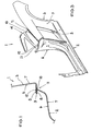
- FIG. 1 shows a section through a multi-piece, complex metal sheet molded part 1 .
- the molded part shown here is the rear side part 1 of a body.
- two smaller sheet metal parts 2 , 3 of the multi-piece construction are shown.
- the side part 1 as a complex, larger sheet metal molded part 1 has a laterally covered, no longer visible inside 6 and a later painted, visible outside 7 .
- a flange-shaped extension 8 is formed, which is directed in the direction of the inside 6 of the body component.
- the flange-shaped extension 8 of the door frame 2 is connected to the flange-shaped extension 8 of the rear fender 3 .
- the flange-shaped extensions 8 are approximately 8 mm long and are formed on the inside 6 of the side part 1 .
- a fixed, permanent connection 9 is attached between the flange-shaped extensions 8 .
- the fixed connection was achieved using MIG welding.
- the weld 9 is butted on the flange ends.
- riveting on the flange surfaces would be just as useful.
- the body parts shown here are parts made of aluminum or an aluminum alloy.
- the fixed connection 9 between the two body parts 2 , 3 is arranged on the inside 6 , so that it is not visible from the outside.
- an adhesive 10 is applied.
- the adhesive is an epoxy resin adhesive that adheres well to the aluminum surfaces on the one hand, that can be reworked in such a way that the transition surfaces between the aluminum and the adhesive lamination can be formed homogeneously, that is weather-resistant, has a similar surface structure to the aluminum sheet, and that is paintable. As a result, after painting the side part 1, the impression can be given from the outside that the side part 1 is in one piece.
- the essence of this exemplary embodiment is that the fixed connection 9 is attached to the rear side 6 of the molded part 1, 2, 3 , while a second connection 10 is arranged on the outer surface 7 for laminating the fixed connection.
- FIG. 2 shows the individual smaller molded parts 2, 3, 4 which are required to build a complete rear side part 1 .
- the door frame 2 is made of aluminum and has flange-like extensions 8 at its connecting points 9 , at which it is later connected to the other molded parts 3 , 4 .
- the length of the flange-like extension 8 is approximately 8 mm. However, other lengths can be used that are adapted to the respective type of connection.
- the flange-shaped extensions 8 must be designed so that the lever forces on the individual parts can only have a slight effect.
- the flange-shaped extension 8 of the rear fender 3 is later applied and connected.
- the rear fender 3 is constructed in several pieces.
- An air inlet 5 is attached here, which together with the remaining fender 3 likewise has a flange-shaped extension 8 which is later connected to the flange-shaped extension 8 on the door frame 2 .
- a flange-shaped extension 8 which is later connected to the flange-shaped extension 8 on the door frame 2 .
- At the top of the fender there is another flange-shaped extension 8 which has a different kink angle with respect to the fender, like the side flange-shaped extension 8 .
- the upper cover 4 is attached to the upper flange-shaped extension 8 of the fender 3 , in which the two flange-shaped extensions 8 of the upper cover 4 and the rear fender 3 are butt-welded to one another.
- FIG. 3 shows a large sheet metal molded part 1 with a complex geometry, which has a plurality of adhesive laminations 10 on its outer surface 7 .
- These adhesive laminations 10 form striking design edges 11 .
- Design edges of this type which after painting give the impression that they have been stamped into the molded part, cannot be realized at all with a conventional process, or only with great effort.
- the fixed connections 9 between the individual parts 2 , 3 , 4 is located on the rear 6 on the flange-shaped extensions, which cannot be seen from the outside.
- the gap at the flange-shaped extensions is covered by the adhesive 10 .
- the adhesive itself does not serve as a fixed connection between the parts, but only as a kind of filler that is invisible after painting and covers the gap between the individual parts.
- any geometry for the Body shell made entirely of sheet metal, especially for Design aluminum bodies.
- Such molded parts are used primarily for Sports car bodies in lightweight construction required. However, too other uses of such molded parts e.g. B. conceivable in model making.
Landscapes
- Engineering & Computer Science (AREA)
- Mechanical Engineering (AREA)
- Chemical & Material Sciences (AREA)
- Combustion & Propulsion (AREA)
- Transportation (AREA)
- Body Structure For Vehicles (AREA)
- Laminated Bodies (AREA)
Abstract
Description
- Figur 1:
- Schnittdarstellung eines mehrstückigen Metallblech-Formteils
- Figur 2:
- Einzelne kleinere Metallblech-Formteile zum Aufbau eines hinteren Seitenteils einer Karosserie
- Figur 3:
- Komplexes einstückiges Seitenteil einer Karosserie
Claims (6)
- Komplexes größeres Metallblech-Formteil (1) mit einer Innenseite (6) und einer Außenseite (7) bestehend ausmehreren kleineren Metallblech-Formteilen (2, 3, 4), die jeweils zumindest eine zur Innenseite (6) ausgebildete flanschförmige Verlängerung (8) aufweisen,wobei an mindestens zwei benachbarten flanschförmigen Verlängerungen (8) von benachbarten kleineren Formteilen (2, 3, 4) eine feste Verbindung (9) ausgebildet ist undauf der Außenseite (7) ein Kleber (10) aufgebracht ist, der sich über der festen Verbindung (9) befindet, um den Spalt (12) zwischen den beiden benachbarten flanschförmigen Verlängerungen (8) der kleineren Formteile (2, 3, 4) abzudecken.
- Größeres Formteil (1) nach Patentanspruch 1, dadurch gekennzeichnet, dass
die feste Verbindung (9) zwischen den kleineren Formteilen (2, 3, 4) eine Schweißverbindung ist, die stumpf auf den flanschförmigen Verlängerungen (8) angebracht ist. - Größeres Formteil (1) nach Patentanspruch 1, dadurch gekennzeichnet, dass
die feste Verbindung (9) zwischen den kleineren Formteilen (2, 3, 4) eine Nietverbindung ist. - Größeres Formteil (1) nach Patentanspruch 1, dadurch gekennzeichnet, dass
der Kleber (10) ein Epoxydharzkleber ist. - Verwendung eines größeren Formteils (1) nach Patentanspruch 1, in der Außenverkleidung eines Fahrzeugs.
- Verfahren zur Herstellung größerer komplexer Metallblech-Formteile (1) aus kleineren, flanschförmige Verlängerungen (8) aufweisenden Metallblech-Formteilen (2, 3, 4), wobei die Formteile (1, 2, 3, 4) eine Innenseite (6) und eine Außenseite (7) aufweisen bei demzuerst mindestens zwei der kleineren Formteile (2, 3, 4) an ihren auf die Innenseite (6) ragenden, flanschförmigen Verlängerungen (8) zusammengesetzt und dort fest miteinander verbunden werden, und dannder Spalt (12) zwischen den benachbarten flanschförmigen Verlängerungen (8) auf der Außenseite (7) mit einer Klebemasse (10) abgedeckt wird.
Applications Claiming Priority (2)
| Application Number | Priority Date | Filing Date | Title |
|---|---|---|---|
| DE10309634 | 2003-03-04 | ||
| DE2003109634 DE10309634A1 (de) | 2003-03-04 | 2003-03-04 | Metallblech-Formteil und Verfahren zur Herstellung eines Metallblechformteils |
Publications (2)
| Publication Number | Publication Date |
|---|---|
| EP1454818A1 true EP1454818A1 (de) | 2004-09-08 |
| EP1454818B1 EP1454818B1 (de) | 2006-08-30 |
Family
ID=32797826
Family Applications (1)
| Application Number | Title | Priority Date | Filing Date |
|---|---|---|---|
| EP20040004788 Expired - Lifetime EP1454818B1 (de) | 2003-03-04 | 2004-03-02 | Metallblech-Formteil und Verfahren zur Herstellung eines Metallblech-Formteils |
Country Status (2)
| Country | Link |
|---|---|
| EP (1) | EP1454818B1 (de) |
| DE (2) | DE10309634A1 (de) |
Cited By (3)
| Publication number | Priority date | Publication date | Assignee | Title |
|---|---|---|---|---|
| WO2008087024A1 (en) * | 2007-01-18 | 2008-07-24 | Toyota Motor Corporation | Composite of sheet metal parts |
| FR2940955A1 (fr) * | 2009-01-14 | 2010-07-16 | Peugeot Citroen Automobiles Sa | Element en tole destine a etre assemble au moyen d'un cordon de calage a un autre element tel qu'un element de la carrosserie d'un vehicule automobile |
| WO2017046494A1 (fr) * | 2015-09-18 | 2017-03-23 | Peugeot Citroen Automobiles Sa | Procede d'assemblage entre deux elements en tole metallique |
Families Citing this family (3)
| Publication number | Priority date | Publication date | Assignee | Title |
|---|---|---|---|---|
| CN101264771B (zh) * | 2007-12-27 | 2010-11-17 | 奇瑞汽车股份有限公司 | 一种车身外表面焊接结构及其焊接方法 |
| DE102008006103B4 (de) | 2008-01-25 | 2017-12-28 | Dr. Ing. H.C. F. Porsche Aktiengesellschaft | Kraftfahrzeug |
| DE102008060410B4 (de) | 2008-11-28 | 2023-08-31 | Dr. Ing. H.C. F. Porsche Aktiengesellschaft | Kraftfahrzeug mit Schwellerblende |
Citations (3)
| Publication number | Priority date | Publication date | Assignee | Title |
|---|---|---|---|---|
| US4471519A (en) * | 1981-09-14 | 1984-09-18 | Fiat Auto S.P.A. | Method for mutually fixing vehicle body elements |
| DE4444817A1 (de) * | 1994-12-15 | 1996-06-20 | Bayerische Motoren Werke Ag | Verlagerbares Karosserieteil |
| US5860694A (en) * | 1994-03-01 | 1999-01-19 | Mercedes-Benz Ag | Integral bodyshell structure for a motor vehicle and method of producing the bodyshell structure |
Family Cites Families (5)
| Publication number | Priority date | Publication date | Assignee | Title |
|---|---|---|---|---|
| DE19705864C2 (de) * | 1997-02-15 | 2002-05-02 | Daimler Chrysler Ag | Dichte Verbindung zweier korrosionsgeschützter Bleche |
| DE19737966A1 (de) * | 1997-08-30 | 1998-08-06 | Daimler Benz Ag | Klebverbindung zwischen zwei Bauteilen |
| DE19748786C2 (de) * | 1997-11-05 | 1999-10-21 | Daimler Chrysler Ag | Klebeverbindung von Blechteilen |
| GB2348175A (en) * | 1999-03-26 | 2000-09-27 | Rover Group | Vehicle body having bulkhead secured by adhesive or sealant |
| DE19915278B4 (de) * | 1999-04-03 | 2013-12-05 | Volkswagen Ag | Kantenverbindung von zwei Bauteilen, insbesondere zwischen einem Dachblech und einem oberen Seitenteil einer Kraftfahrzeug-Karosserie |
-
2003
- 2003-03-04 DE DE2003109634 patent/DE10309634A1/de not_active Withdrawn
-
2004
- 2004-03-02 DE DE200450001295 patent/DE502004001295D1/de not_active Expired - Lifetime
- 2004-03-02 EP EP20040004788 patent/EP1454818B1/de not_active Expired - Lifetime
Patent Citations (3)
| Publication number | Priority date | Publication date | Assignee | Title |
|---|---|---|---|---|
| US4471519A (en) * | 1981-09-14 | 1984-09-18 | Fiat Auto S.P.A. | Method for mutually fixing vehicle body elements |
| US5860694A (en) * | 1994-03-01 | 1999-01-19 | Mercedes-Benz Ag | Integral bodyshell structure for a motor vehicle and method of producing the bodyshell structure |
| DE4444817A1 (de) * | 1994-12-15 | 1996-06-20 | Bayerische Motoren Werke Ag | Verlagerbares Karosserieteil |
Cited By (8)
| Publication number | Priority date | Publication date | Assignee | Title |
|---|---|---|---|---|
| WO2008087024A1 (en) * | 2007-01-18 | 2008-07-24 | Toyota Motor Corporation | Composite of sheet metal parts |
| EP1949981A1 (de) | 2007-01-18 | 2008-07-30 | Toyota Motor Corporation | Zusammenbau von Blechteilen |
| JP2010516531A (ja) * | 2007-01-18 | 2010-05-20 | トヨタ自動車株式会社 | 金属薄板部品の複合体 |
| US8631996B2 (en) | 2007-01-18 | 2014-01-21 | Toyota Motor Corporation | Composite of sheet metal parts |
| FR2940955A1 (fr) * | 2009-01-14 | 2010-07-16 | Peugeot Citroen Automobiles Sa | Element en tole destine a etre assemble au moyen d'un cordon de calage a un autre element tel qu'un element de la carrosserie d'un vehicule automobile |
| WO2010081951A1 (fr) * | 2009-01-14 | 2010-07-22 | Peugeot Citroën Automobiles SA | Element en tole destine a etre assemble au moyen d'un cordon de calage a un autre element tel qu'un element de la carrosserie d'un vehicule automobile |
| WO2017046494A1 (fr) * | 2015-09-18 | 2017-03-23 | Peugeot Citroen Automobiles Sa | Procede d'assemblage entre deux elements en tole metallique |
| FR3041319A1 (fr) * | 2015-09-18 | 2017-03-24 | Peugeot Citroen Automobiles Sa | Procede d’assemblage entre deux elements en tole metallique. |
Also Published As
| Publication number | Publication date |
|---|---|
| EP1454818B1 (de) | 2006-08-30 |
| DE502004001295D1 (de) | 2006-10-12 |
| DE10309634A1 (de) | 2004-09-23 |
Similar Documents
| Publication | Publication Date | Title |
|---|---|---|
| DE69612409T2 (de) | Verbundprofil für Fahrgestell | |
| DE102010024704A1 (de) | Dachanordnung für ein Fahrzeug | |
| DE102011009892A1 (de) | Kraftfahrzeugbauteil und Verfahren zur Herstellung des Kraftfahrzeugbauteils | |
| DE102007047036A1 (de) | Verfahren zur Herstellung eines weitestgehend flächenförmigen Bauteileverbundes und weitestgehend flächenförmiger Bauteileverbund dazu | |
| DE102012023653A1 (de) | Kraftfahrzeugkarosserie mit Leichtbauteil | |
| DE4300398A1 (de) | Verfahren zur Herstellung einer Kraftfahrzeugkarosserie | |
| DE102016224431A1 (de) | Karosseriebauteil | |
| DE102010054097A1 (de) | Verfahren zur Herstellung eines Metall-Faserverbund-Bauteiles | |
| DE202008017596U1 (de) | Formbauteil aus Stahlblech | |
| WO1998018670A1 (de) | Cpkd-karosserie | |
| DE102012103332A1 (de) | Verfahren zum Herstellen großer Leichtbleche | |
| DE102011121381A1 (de) | Verfahren zur Herstellung eines Aufprallquerträgers sowie Aufprallquerträger | |
| EP1454818B1 (de) | Metallblech-Formteil und Verfahren zur Herstellung eines Metallblech-Formteils | |
| DE102018207488A1 (de) | Verfahren zur Herstellung eines Blechbauteils | |
| DE10025360C1 (de) | Verbundzierteil und Herstellungsverfahren | |
| DE10336187A1 (de) | Hybridbauteil und zugehöriges Herstellungsverfahren | |
| DE2558332A1 (de) | Wandungen, insbesondere fuer aufbauten von fahrzeugen | |
| DE102012020182A1 (de) | Strukturelement für eine Kraftfahrzeug-Rohbaustruktur | |
| WO2007039630A1 (de) | Aus mindestens zwei vorkonfektionierten baugruppen zusammengesetzte fahrzeugkarosserie und verfahren zu ihrer herstellung | |
| DE102008013830A1 (de) | Verfahren zur Herstellung eines Hohlprofils, Hohlprofil sowie Fahrzeugkarosserie | |
| DE102014206196A1 (de) | Dachrahmen für eine Fahrzeugkarosserie | |
| EP2871116B1 (de) | Formteil für Kraftfahrzeuge | |
| DE202012103728U1 (de) | Energieabsorptionsbauteil für ein Fahrzeug sowie Stoßfängerbaugruppe umfassend ein solches Bauteil und einen Stoßfängerquerträger | |
| DE3528118A1 (de) | Karosserieteil fuer kraftfahrzeuge, insbesondere motorhaube, und verfahren zur herstellung | |
| DE102009032651A1 (de) | Verfahren zur Herstellung einer Karosserie für ein Kraftfahrzeug und Karosserie |
Legal Events
| Date | Code | Title | Description |
|---|---|---|---|
| PUAI | Public reference made under article 153(3) epc to a published international application that has entered the european phase |
Free format text: ORIGINAL CODE: 0009012 |
|
| AK | Designated contracting states |
Kind code of ref document: A1 Designated state(s): AT BE BG CH CY CZ DE DK EE ES FI FR GB GR HU IE IT LI LU MC NL PL PT RO SE SI SK TR |
|
| AX | Request for extension of the european patent |
Extension state: AL LT LV MK |
|
| 17P | Request for examination filed |
Effective date: 20050308 |
|
| AKX | Designation fees paid |
Designated state(s): DE FR IT |
|
| GRAP | Despatch of communication of intention to grant a patent |
Free format text: ORIGINAL CODE: EPIDOSNIGR1 |
|
| GRAS | Grant fee paid |
Free format text: ORIGINAL CODE: EPIDOSNIGR3 |
|
| GRAA | (expected) grant |
Free format text: ORIGINAL CODE: 0009210 |
|
| AK | Designated contracting states |
Kind code of ref document: B1 Designated state(s): DE FR IT |
|
| PG25 | Lapsed in a contracting state [announced via postgrant information from national office to epo] |
Ref country code: IT Free format text: LAPSE BECAUSE OF FAILURE TO SUBMIT A TRANSLATION OF THE DESCRIPTION OR TO PAY THE FEE WITHIN THE PRESCRIBED TIME-LIMIT;WARNING: LAPSES OF ITALIAN PATENTS WITH EFFECTIVE DATE BEFORE 2007 MAY HAVE OCCURRED AT ANY TIME BEFORE 2007. THE CORRECT EFFECTIVE DATE MAY BE DIFFERENT FROM THE ONE RECORDED. Effective date: 20060830 |
|
| REF | Corresponds to: |
Ref document number: 502004001295 Country of ref document: DE Date of ref document: 20061012 Kind code of ref document: P |
|
| ET | Fr: translation filed | ||
| PLBE | No opposition filed within time limit |
Free format text: ORIGINAL CODE: 0009261 |
|
| STAA | Information on the status of an ep patent application or granted ep patent |
Free format text: STATUS: NO OPPOSITION FILED WITHIN TIME LIMIT |
|
| 26N | No opposition filed |
Effective date: 20070531 |
|
| REG | Reference to a national code |
Ref country code: FR Ref legal event code: PLFP Year of fee payment: 13 |
|
| PGFP | Annual fee paid to national office [announced via postgrant information from national office to epo] |
Ref country code: FR Payment date: 20160328 Year of fee payment: 13 |
|
| PGFP | Annual fee paid to national office [announced via postgrant information from national office to epo] |
Ref country code: DE Payment date: 20160331 Year of fee payment: 13 |
|
| PGFP | Annual fee paid to national office [announced via postgrant information from national office to epo] |
Ref country code: IT Payment date: 20160331 Year of fee payment: 13 |
|
| REG | Reference to a national code |
Ref country code: DE Ref legal event code: R119 Ref document number: 502004001295 Country of ref document: DE |
|
| REG | Reference to a national code |
Ref country code: FR Ref legal event code: ST Effective date: 20171130 |
|
| PG25 | Lapsed in a contracting state [announced via postgrant information from national office to epo] |
Ref country code: FR Free format text: LAPSE BECAUSE OF NON-PAYMENT OF DUE FEES Effective date: 20170331 Ref country code: DE Free format text: LAPSE BECAUSE OF NON-PAYMENT OF DUE FEES Effective date: 20171003 |
|
| PG25 | Lapsed in a contracting state [announced via postgrant information from national office to epo] |
Ref country code: IT Free format text: LAPSE BECAUSE OF NON-PAYMENT OF DUE FEES Effective date: 20170302 |