EP1451840B1 - Dispositif manuel de positionnement d'un interrupteur - Google Patents
Dispositif manuel de positionnement d'un interrupteur Download PDFInfo
- Publication number
- EP1451840B1 EP1451840B1 EP02788280A EP02788280A EP1451840B1 EP 1451840 B1 EP1451840 B1 EP 1451840B1 EP 02788280 A EP02788280 A EP 02788280A EP 02788280 A EP02788280 A EP 02788280A EP 1451840 B1 EP1451840 B1 EP 1451840B1
- Authority
- EP
- European Patent Office
- Prior art keywords
- rod
- movement
- transfer device
- flexible shaft
- shaft
- Prior art date
- Legal status (The legal status is an assumption and is not a legal conclusion. Google has not performed a legal analysis and makes no representation as to the accuracy of the status listed.)
- Expired - Lifetime
Links
- 230000008878 coupling Effects 0.000 claims description 16
- 238000010168 coupling process Methods 0.000 claims description 16
- 238000005859 coupling reaction Methods 0.000 claims description 16
- 230000001131 transforming effect Effects 0.000 description 6
- 238000009434 installation Methods 0.000 description 3
- 230000007246 mechanism Effects 0.000 description 2
- 238000006073 displacement reaction Methods 0.000 description 1
- 238000005096 rolling process Methods 0.000 description 1
Images

Classifications
-
- H—ELECTRICITY
- H01—ELECTRIC ELEMENTS
- H01H—ELECTRIC SWITCHES; RELAYS; SELECTORS; EMERGENCY PROTECTIVE DEVICES
- H01H3/00—Mechanisms for operating contacts
- H01H3/32—Driving mechanisms, i.e. for transmitting driving force to the contacts
- H01H3/38—Driving mechanisms, i.e. for transmitting driving force to the contacts using spring or other flexible shaft coupling
-
- E—FIXED CONSTRUCTIONS
- E06—DOORS, WINDOWS, SHUTTERS, OR ROLLER BLINDS IN GENERAL; LADDERS
- E06B—FIXED OR MOVABLE CLOSURES FOR OPENINGS IN BUILDINGS, VEHICLES, FENCES OR LIKE ENCLOSURES IN GENERAL, e.g. DOORS, WINDOWS, BLINDS, GATES
- E06B9/00—Screening or protective devices for wall or similar openings, with or without operating or securing mechanisms; Closures of similar construction
- E06B9/56—Operating, guiding or securing devices or arrangements for roll-type closures; Spring drums; Tape drums; Counterweighting arrangements therefor
- E06B9/68—Operating devices or mechanisms, e.g. with electric drive
- E06B9/72—Operating devices or mechanisms, e.g. with electric drive comprising an electric motor positioned inside the roller
-
- E—FIXED CONSTRUCTIONS
- E06—DOORS, WINDOWS, SHUTTERS, OR ROLLER BLINDS IN GENERAL; LADDERS
- E06B—FIXED OR MOVABLE CLOSURES FOR OPENINGS IN BUILDINGS, VEHICLES, FENCES OR LIKE ENCLOSURES IN GENERAL, e.g. DOORS, WINDOWS, BLINDS, GATES
- E06B9/00—Screening or protective devices for wall or similar openings, with or without operating or securing mechanisms; Closures of similar construction
- E06B9/56—Operating, guiding or securing devices or arrangements for roll-type closures; Spring drums; Tape drums; Counterweighting arrangements therefor
- E06B9/68—Operating devices or mechanisms, e.g. with electric drive
- E06B9/76—Operating devices or mechanisms, e.g. with electric drive using crank handles
Definitions
- the present invention relates to a device for manually positioning a switch in a control device of an electric shutter motor or the like comprising a rod.
- the object of the invention is to improve the devices of the prior art and to produce a simple, inexpensive and compact manual positioning device.
- the positioning latitude on the structure or the box of the flap of this device must also be wide to overcome the constraints of installation, use, aesthetics or standardization.
- the manual positioning device is characterized in that it comprises a flexible shaft controlled by the rod and transmitting a rotational movement or a translational movement to the switch of the control device and in that it comprises a device for transferring movement between the rod and the flexible shaft.
- the motion transfer device may be attached to the most convenient location for installation, for example, on the building structure or on the box containing the shutter mechanism or the like.
- the motion transfer device can transform a rotational movement or a translational movement of the rod into a rotational movement or a translational movement of the flexible shaft.
- the rod and the motion transfer device have mutual coupling means for making the rod removable.
- the flexible shaft may consist of a sheathed or unsheathed cable allowing, according to the embodiments, to transmit a rotational movement or a translational movement to the switch of the control device.
- the motion transfer device transforming a rotational movement into a translation movement or a translational movement into a rotational movement can be achieved simply by means of an eccentric but also by means of a helical connection or a cam and follower assembly. .
- the manual positioning device according to the invention can of course be used to position other bistable mechanisms.
- the figure 1 is a schematic sectional view of a rod control of a roller shutter using a motion transfer device attached to the casing of the shutter.
- the figure 2 is a view similar to the figure 1 a rod drive using a motion transfer device attached to the structure supporting the roller shutter.
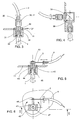
- the figure 3 is a sectional detail view of a first embodiment of the transfer device transforming a rotational movement of the rod into a rotational movement of the flexible shaft.
- the figure 4 is a sectional detail view of the transfer device transforming a movement of rotating the rod in a rotational movement of the flexible shaft by means of a pair of bevel gears.
- the figure 5 is a sectional detail view of a second embodiment of the transfer device transforming a rotational movement of the rod into a translation movement of the flexible shaft.
- the figure 6 is a top detail view of the transfer device according to the second embodiment.
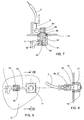
- the figure 7 is a sectional detail view of a third embodiment of the transfer device transforming a translation movement of the rod into a translation movement of the flexible shaft.
- the figure 8 is a sectional detail view of a fourth embodiment of the transfer device transforming a translation movement of the rod into a rotational movement of the flexible shaft.
- the figure 9 is a top detail view of the transfer device according to the fourth embodiment.
- the device according to the invention consists of a rod 1 connected to a motion transfer device 3 fixed on the structure of a building 10 or on the box 11 of a rolling shutter 12.
- This movement transfer device 3 is connected to a flexible shaft 2 which transmits its movement to a switch of a control device 13 of the shutter motor.
- the rod 1 is intended to be actuated by the user.
- the switch of the control device 13 may be, by this action, positioned for example in the states "opening” or “closing” and optionally "stop".
- the device is shown with a motion transfer device 3, fixed on the underside of the casing 11 of the shutter.
- the device is shown with a motion transfer device 3, fixed on the structure 10 where is installed the shutter.
- the transfer device 3 shown transforms a rotational movement of the rod 1 into a rotational movement of the flexible shaft 2.
- the transfer device is fixed on the casing 11 via a housing 31 in which is
- This shaft 32 has at one of its ends a coupling means 33 allowing, with the cooperation of the coupling means 34 provided at one of the ends of the rod 1, to link in rotation. the rod 32 to the shaft 32.
- the shaft 32 has at its other end a coupling means 37 allowing, with the cooperation of the coupling means 36 provided for in FIG. the end of the flexible shaft 2, to connect in rotation the flexible shaft 2 to the shaft 32.
- the rod 1 and the flexible shaft 2 are by these means connected in rotation.
- this transfer device 3 has a bevel gear.
- Such a device can be produced, for example, by virtue of a pair of bevel gear wheels 38, 39 meshing with each other as shown in FIG. figure 4 .
- the transfer device 3 shown transforms a rotational movement of the rod 1 into a translational movement of the flexible shaft 2 guided by a sheath 4.
- the transfer device is fixed on the casing 11 via a housing 41 in which is mounted in pivot connection a shaft 42.
- This shaft 42 has at one of its ends a coupling means 44 allowing, with the cooperation of the coupling means to rotate the rod 1 to the shaft 42.
- the shaft 42 is at its other end terminated by a lever 43 at the end of which is a hole and a set screw 46.
- One of the ends of the flexible shaft 2 is connected to this lever 43 through the hole in it is immobilized by the pressure screw 46.
- the transfer device 3 shown converts a translational movement of the rod 1 into a translational movement of the flexible shaft 2 guided by a sheath 4.
- the transfer device is fixed on the casing 11 via a housing 61 in which is mounted in slide connection a shaft 62.
- This shaft 62 has at one of its ends 63 a coupling means 64 allowing, with the cooperation of the coupling means 65 provided at one end of the rod 1, to transmit a translational movement of the rod 1 to the shaft 62.
- the shaft 62 has at its other end 66 a coupling means 67 allowing, with the cooperation of the coupling means 68 provided in the one ends of the flexible shaft 2, to transmit a translational movement of the shaft 62 to the flexible shaft 2.
- the transfer device 3 shown transforms a translation movement of the rod 1 into a rotational movement of the flexible shaft 2.
- the transfer device is fixed on the casing 11 via a housing 71 in which is pivotally mounted shaft 72.
- This shaft 72 has at one of its ends a coupling means 76 allowing, with the cooperation of the coupling means 77 provided at one end of the flexible shaft 2, to bind in rotation the tree 2 at the shaft 72.
- the shaft 72 is at its other end terminated by a lever 73 at the end of which is a coupling means 74 allowing, with the cooperation of the coupling means 75 provided to one of the ends of the rod 1, to transform a translational movement of the rod 1 into a rotational movement of the shaft 72.
- the translational movement of the rod 1 therefore causes the rotational movement of the flexible shaft 2.
Landscapes
- Engineering & Computer Science (AREA)
- Structural Engineering (AREA)
- Architecture (AREA)
- Civil Engineering (AREA)
- Operating, Guiding And Securing Of Roll- Type Closing Members (AREA)
- Switches With Compound Operations (AREA)
- Control Of Position Or Direction (AREA)
- Vehicle Body Suspensions (AREA)
Applications Claiming Priority (3)
| Application Number | Priority Date | Filing Date | Title |
|---|---|---|---|
| FR0115891A FR2833404B1 (fr) | 2001-12-07 | 2001-12-07 | Dispositif manuel de positionnement d'interrupteur |
| FR0115891 | 2001-12-07 | ||
| PCT/IB2002/004976 WO2003049127A1 (fr) | 2001-12-07 | 2002-11-27 | Dispositif manuel de positionnement d'un interrupteur |
Publications (2)
| Publication Number | Publication Date |
|---|---|
| EP1451840A1 EP1451840A1 (fr) | 2004-09-01 |
| EP1451840B1 true EP1451840B1 (fr) | 2008-04-30 |
Family
ID=8870261
Family Applications (1)
| Application Number | Title | Priority Date | Filing Date |
|---|---|---|---|
| EP02788280A Expired - Lifetime EP1451840B1 (fr) | 2001-12-07 | 2002-11-27 | Dispositif manuel de positionnement d'un interrupteur |
Country Status (9)
| Country | Link |
|---|---|
| EP (1) | EP1451840B1 (cg-RX-API-DMAC7.html) |
| JP (1) | JP2005511931A (cg-RX-API-DMAC7.html) |
| CN (1) | CN100479078C (cg-RX-API-DMAC7.html) |
| AT (1) | ATE393957T1 (cg-RX-API-DMAC7.html) |
| AU (1) | AU2002353259A1 (cg-RX-API-DMAC7.html) |
| DE (1) | DE60226338T2 (cg-RX-API-DMAC7.html) |
| ES (1) | ES2224911T3 (cg-RX-API-DMAC7.html) |
| FR (1) | FR2833404B1 (cg-RX-API-DMAC7.html) |
| WO (1) | WO2003049127A1 (cg-RX-API-DMAC7.html) |
Families Citing this family (5)
| Publication number | Priority date | Publication date | Assignee | Title |
|---|---|---|---|---|
| WO2007000478A1 (es) * | 2005-04-04 | 2007-01-04 | Lansac Aquilué, Eloysa | Persiana enrollable |
| ES2245263B1 (es) * | 2005-04-04 | 2007-07-01 | Agustin Auria Perez | Persiana enrollable. |
| DE202009010505U1 (de) | 2009-08-04 | 2010-12-16 | Arca Beteiligungen Gmbh | Verdunkelungsvorrichtung |
| US10851587B2 (en) | 2016-10-19 | 2020-12-01 | Hunter Douglas Inc. | Motor assemblies for architectural coverings |
| US11486198B2 (en) | 2019-04-19 | 2022-11-01 | Hunter Douglas Inc. | Motor assemblies for architectural coverings |
Family Cites Families (4)
| Publication number | Priority date | Publication date | Assignee | Title |
|---|---|---|---|---|
| US519354A (en) * | 1894-05-08 | William hy | ||
| US4620077A (en) * | 1985-02-19 | 1986-10-28 | Cts Corporation | Integral switch connector with remote actuator |
| DE9112164U1 (de) * | 1991-09-30 | 1992-02-13 | Kimetec GmbH Medizintechnik, 71254 Ditzingen | Schaltwelle für ein Gerät |
| FR2803332B1 (fr) * | 1999-12-29 | 2002-07-26 | Somfy | Dispositif de positionnement de moyen mecanique dans un dispositif de commande |
-
2001
- 2001-12-07 FR FR0115891A patent/FR2833404B1/fr not_active Expired - Fee Related
-
2002
- 2002-11-27 WO PCT/IB2002/004976 patent/WO2003049127A1/fr not_active Ceased
- 2002-11-27 EP EP02788280A patent/EP1451840B1/fr not_active Expired - Lifetime
- 2002-11-27 JP JP2003550235A patent/JP2005511931A/ja active Pending
- 2002-11-27 CN CN02827234.XA patent/CN100479078C/zh not_active Expired - Fee Related
- 2002-11-27 AT AT02788280T patent/ATE393957T1/de not_active IP Right Cessation
- 2002-11-27 DE DE60226338T patent/DE60226338T2/de not_active Expired - Lifetime
- 2002-11-27 AU AU2002353259A patent/AU2002353259A1/en not_active Abandoned
- 2002-11-27 ES ES02788280T patent/ES2224911T3/es not_active Expired - Lifetime
Also Published As
| Publication number | Publication date |
|---|---|
| AU2002353259A1 (en) | 2003-06-17 |
| EP1451840A1 (fr) | 2004-09-01 |
| CN1615531A (zh) | 2005-05-11 |
| ES2224911T1 (es) | 2005-03-16 |
| WO2003049127A1 (fr) | 2003-06-12 |
| JP2005511931A (ja) | 2005-04-28 |
| DE60226338T2 (de) | 2009-06-18 |
| DE60226338D1 (cg-RX-API-DMAC7.html) | 2008-06-12 |
| CN100479078C (zh) | 2009-04-15 |
| FR2833404A1 (fr) | 2003-06-13 |
| ES2224911T3 (es) | 2008-11-01 |
| FR2833404B1 (fr) | 2004-08-27 |
| ATE393957T1 (de) | 2008-05-15 |
Similar Documents
| Publication | Publication Date | Title |
|---|---|---|
| EP0070230A1 (fr) | Mécanisme de débrayage pour appareil de traction agissant sur un câble qui le traverse | |
| CH625735A5 (cg-RX-API-DMAC7.html) | ||
| EP1324466B1 (fr) | Dispositif de frein a disques et de transmission de couple | |
| EP1451840B1 (fr) | Dispositif manuel de positionnement d'un interrupteur | |
| FR2582730A1 (fr) | Dispositif de reglage d'une butee couplee avec un organe de commande d'un moteur a combustion interne | |
| EP0019501B1 (fr) | Dispositif de commande d'un rétroviseur extérieur de l'intérieur d'un véhicule | |
| FR2816977A1 (fr) | Serrure a commande electrique | |
| WO2004059110A1 (fr) | Procede de commande d'une serrure electrique munie d'un embrayage | |
| FR2646202A1 (fr) | Dispositif de manoeuvre pour l'ouverture et la fermeture d'au moins un volet | |
| FR2769037A1 (fr) | Dispositif de verrouillage comportant un doigt de transmission commande par came | |
| FR2591271A1 (fr) | Dispositif pour entrainement de portes pivotantes | |
| FR2591650A1 (fr) | Dispositif de manoeuvre pour volets ou persiennes a un ou deux vantaux pivotants | |
| EP0448515A1 (fr) | Actuateur linéaire | |
| EP0142398A1 (fr) | Dispositif électromécanique de manoeuvre d'un vantail de porte ou de portail | |
| FR2914073A1 (fr) | Montre a dispositif de commande et de verrouillage du remontoir | |
| FR2681092A1 (fr) | Dispositif d'arret de porte du type a charniere, notamment pour une porte de vehicule. | |
| EP1458945B1 (fr) | Serrure electrique | |
| CH717826A2 (fr) | Chariot à pédale pour l'ouverture et la fermeture d'un battant, notamment d'un vantail d'une porte. | |
| EP0132171B1 (fr) | Dispositif de commande d'un miroir de rétroviseur extérieur de l'intérieur d'un véhicule | |
| WO1988003219A1 (fr) | Dispositif et appareil pour la monoeuvre des volets roulants | |
| EP0036379A1 (fr) | Moto-réducteur électrique pour la mécanisation des dispositifs de stores et de volets roulants à commande par manivelle | |
| FR2554651A1 (fr) | Dispositif d'accouplement d'un alternateur et d'un moteur d'un vehicule | |
| FR2664643A1 (fr) | Dispositif pour ouvrir (ou fermer) manuellement en securite une porte basculante, a commande electrique. | |
| FR2653797A1 (fr) | Dispositif d'actionnement controle pour clapet de chasse-d'eau. | |
| FR2622349A1 (fr) | Temporisateur a rearmement manuel |
Legal Events
| Date | Code | Title | Description |
|---|---|---|---|
| PUAI | Public reference made under article 153(3) epc to a published international application that has entered the european phase |
Free format text: ORIGINAL CODE: 0009012 |
|
| 17P | Request for examination filed |
Effective date: 20040527 |
|
| AK | Designated contracting states |
Kind code of ref document: A1 Designated state(s): AT BE BG CH CY CZ DE DK EE ES FI FR GB GR IE IT LI LU MC NL PT SE SK TR |
|
| AX | Request for extension of the european patent |
Extension state: AL LT LV MK RO SI |
|
| RAP1 | Party data changed (applicant data changed or rights of an application transferred) |
Owner name: SOMFY SAS |
|
| 17Q | First examination report despatched |
Effective date: 20070411 |
|
| GRAP | Despatch of communication of intention to grant a patent |
Free format text: ORIGINAL CODE: EPIDOSNIGR1 |
|
| GRAS | Grant fee paid |
Free format text: ORIGINAL CODE: EPIDOSNIGR3 |
|
| GRAA | (expected) grant |
Free format text: ORIGINAL CODE: 0009210 |
|
| AK | Designated contracting states |
Kind code of ref document: B1 Designated state(s): AT BE BG CH CY CZ DE DK EE ES FI FR GB GR IE IT LI LU MC NL PT SE SK TR |
|
| REG | Reference to a national code |
Ref country code: GB Ref legal event code: FG4D Free format text: NOT ENGLISH |
|
| REG | Reference to a national code |
Ref country code: CH Ref legal event code: EP |
|
| REG | Reference to a national code |
Ref country code: IE Ref legal event code: FG4D |
|
| REF | Corresponds to: |
Ref document number: 60226338 Country of ref document: DE Date of ref document: 20080612 Kind code of ref document: P |
|
| NLV1 | Nl: lapsed or annulled due to failure to fulfill the requirements of art. 29p and 29m of the patents act | ||
| PG25 | Lapsed in a contracting state [announced via postgrant information from national office to epo] |
Ref country code: BG Free format text: LAPSE BECAUSE OF FAILURE TO SUBMIT A TRANSLATION OF THE DESCRIPTION OR TO PAY THE FEE WITHIN THE PRESCRIBED TIME-LIMIT Effective date: 20080730 Ref country code: FI Free format text: LAPSE BECAUSE OF FAILURE TO SUBMIT A TRANSLATION OF THE DESCRIPTION OR TO PAY THE FEE WITHIN THE PRESCRIBED TIME-LIMIT Effective date: 20080430 Ref country code: PT Free format text: LAPSE BECAUSE OF FAILURE TO SUBMIT A TRANSLATION OF THE DESCRIPTION OR TO PAY THE FEE WITHIN THE PRESCRIBED TIME-LIMIT Effective date: 20080930 Ref country code: NL Free format text: LAPSE BECAUSE OF FAILURE TO SUBMIT A TRANSLATION OF THE DESCRIPTION OR TO PAY THE FEE WITHIN THE PRESCRIBED TIME-LIMIT Effective date: 20080430 |
|
| REG | Reference to a national code |
Ref country code: ES Ref legal event code: FG2A Ref document number: 2224911 Country of ref document: ES Kind code of ref document: T3 |
|
| PG25 | Lapsed in a contracting state [announced via postgrant information from national office to epo] |
Ref country code: AT Free format text: LAPSE BECAUSE OF FAILURE TO SUBMIT A TRANSLATION OF THE DESCRIPTION OR TO PAY THE FEE WITHIN THE PRESCRIBED TIME-LIMIT Effective date: 20080430 |
|
| REG | Reference to a national code |
Ref country code: IE Ref legal event code: FD4D |
|
| PG25 | Lapsed in a contracting state [announced via postgrant information from national office to epo] |
Ref country code: CZ Free format text: LAPSE BECAUSE OF FAILURE TO SUBMIT A TRANSLATION OF THE DESCRIPTION OR TO PAY THE FEE WITHIN THE PRESCRIBED TIME-LIMIT Effective date: 20080430 Ref country code: SE Free format text: LAPSE BECAUSE OF FAILURE TO SUBMIT A TRANSLATION OF THE DESCRIPTION OR TO PAY THE FEE WITHIN THE PRESCRIBED TIME-LIMIT Effective date: 20080731 Ref country code: IE Free format text: LAPSE BECAUSE OF FAILURE TO SUBMIT A TRANSLATION OF THE DESCRIPTION OR TO PAY THE FEE WITHIN THE PRESCRIBED TIME-LIMIT Effective date: 20080430 Ref country code: DK Free format text: LAPSE BECAUSE OF FAILURE TO SUBMIT A TRANSLATION OF THE DESCRIPTION OR TO PAY THE FEE WITHIN THE PRESCRIBED TIME-LIMIT Effective date: 20080430 |
|
| PG25 | Lapsed in a contracting state [announced via postgrant information from national office to epo] |
Ref country code: SK Free format text: LAPSE BECAUSE OF FAILURE TO SUBMIT A TRANSLATION OF THE DESCRIPTION OR TO PAY THE FEE WITHIN THE PRESCRIBED TIME-LIMIT Effective date: 20080430 |
|
| PLBE | No opposition filed within time limit |
Free format text: ORIGINAL CODE: 0009261 |
|
| STAA | Information on the status of an ep patent application or granted ep patent |
Free format text: STATUS: NO OPPOSITION FILED WITHIN TIME LIMIT |
|
| 26N | No opposition filed |
Effective date: 20090202 |
|
| PG25 | Lapsed in a contracting state [announced via postgrant information from national office to epo] |
Ref country code: EE Free format text: LAPSE BECAUSE OF FAILURE TO SUBMIT A TRANSLATION OF THE DESCRIPTION OR TO PAY THE FEE WITHIN THE PRESCRIBED TIME-LIMIT Effective date: 20080430 |
|
| BERE | Be: lapsed |
Owner name: SOMFY SAS Effective date: 20081130 |
|
| PG25 | Lapsed in a contracting state [announced via postgrant information from national office to epo] |
Ref country code: MC Free format text: LAPSE BECAUSE OF NON-PAYMENT OF DUE FEES Effective date: 20081130 |
|
| REG | Reference to a national code |
Ref country code: CH Ref legal event code: PL |
|
| GBPC | Gb: european patent ceased through non-payment of renewal fee |
Effective date: 20081127 |
|
| PG25 | Lapsed in a contracting state [announced via postgrant information from national office to epo] |
Ref country code: IT Free format text: LAPSE BECAUSE OF FAILURE TO SUBMIT A TRANSLATION OF THE DESCRIPTION OR TO PAY THE FEE WITHIN THE PRESCRIBED TIME-LIMIT Effective date: 20080430 |
|
| PG25 | Lapsed in a contracting state [announced via postgrant information from national office to epo] |
Ref country code: BE Free format text: LAPSE BECAUSE OF NON-PAYMENT OF DUE FEES Effective date: 20081130 |
|
| PG25 | Lapsed in a contracting state [announced via postgrant information from national office to epo] |
Ref country code: CH Free format text: LAPSE BECAUSE OF NON-PAYMENT OF DUE FEES Effective date: 20081130 Ref country code: LI Free format text: LAPSE BECAUSE OF NON-PAYMENT OF DUE FEES Effective date: 20081130 |
|
| PG25 | Lapsed in a contracting state [announced via postgrant information from national office to epo] |
Ref country code: GB Free format text: LAPSE BECAUSE OF NON-PAYMENT OF DUE FEES Effective date: 20081127 |
|
| PG25 | Lapsed in a contracting state [announced via postgrant information from national office to epo] |
Ref country code: CY Free format text: LAPSE BECAUSE OF FAILURE TO SUBMIT A TRANSLATION OF THE DESCRIPTION OR TO PAY THE FEE WITHIN THE PRESCRIBED TIME-LIMIT Effective date: 20080430 Ref country code: LU Free format text: LAPSE BECAUSE OF NON-PAYMENT OF DUE FEES Effective date: 20081127 |
|
| PG25 | Lapsed in a contracting state [announced via postgrant information from national office to epo] |
Ref country code: TR Free format text: LAPSE BECAUSE OF FAILURE TO SUBMIT A TRANSLATION OF THE DESCRIPTION OR TO PAY THE FEE WITHIN THE PRESCRIBED TIME-LIMIT Effective date: 20080430 |
|
| PG25 | Lapsed in a contracting state [announced via postgrant information from national office to epo] |
Ref country code: GR Free format text: LAPSE BECAUSE OF FAILURE TO SUBMIT A TRANSLATION OF THE DESCRIPTION OR TO PAY THE FEE WITHIN THE PRESCRIBED TIME-LIMIT Effective date: 20080731 |
|
| PGFP | Annual fee paid to national office [announced via postgrant information from national office to epo] |
Ref country code: DE Payment date: 20121127 Year of fee payment: 11 Ref country code: FR Payment date: 20121129 Year of fee payment: 11 |
|
| PGFP | Annual fee paid to national office [announced via postgrant information from national office to epo] |
Ref country code: ES Payment date: 20121123 Year of fee payment: 11 |
|
| REG | Reference to a national code |
Ref country code: FR Ref legal event code: ST Effective date: 20140731 |
|
| REG | Reference to a national code |
Ref country code: DE Ref legal event code: R119 Ref document number: 60226338 Country of ref document: DE Effective date: 20140603 |
|
| PG25 | Lapsed in a contracting state [announced via postgrant information from national office to epo] |
Ref country code: DE Free format text: LAPSE BECAUSE OF NON-PAYMENT OF DUE FEES Effective date: 20140603 |
|
| PG25 | Lapsed in a contracting state [announced via postgrant information from national office to epo] |
Ref country code: FR Free format text: LAPSE BECAUSE OF NON-PAYMENT OF DUE FEES Effective date: 20131202 |
|
| REG | Reference to a national code |
Ref country code: ES Ref legal event code: FD2A Effective date: 20150327 |
|
| PG25 | Lapsed in a contracting state [announced via postgrant information from national office to epo] |
Ref country code: ES Free format text: LAPSE BECAUSE OF NON-PAYMENT OF DUE FEES Effective date: 20131128 |