EP1450727B1 - Implant reducteur de flux - Google Patents
Implant reducteur de flux Download PDFInfo
- Publication number
- EP1450727B1 EP1450727B1 EP02772791A EP02772791A EP1450727B1 EP 1450727 B1 EP1450727 B1 EP 1450727B1 EP 02772791 A EP02772791 A EP 02772791A EP 02772791 A EP02772791 A EP 02772791A EP 1450727 B1 EP1450727 B1 EP 1450727B1
- Authority
- EP
- European Patent Office
- Prior art keywords
- flow
- implant
- reducing implant
- section
- reducing
- Prior art date
- Legal status (The legal status is an assumption and is not a legal conclusion. Google has not performed a legal analysis and makes no representation as to the accuracy of the status listed.)
- Expired - Lifetime
Links
Images


Classifications
-
- A—HUMAN NECESSITIES
- A61—MEDICAL OR VETERINARY SCIENCE; HYGIENE
- A61B—DIAGNOSIS; SURGERY; IDENTIFICATION
- A61B17/00—Surgical instruments, devices or methods, e.g. tourniquets
- A61B17/12—Surgical instruments, devices or methods, e.g. tourniquets for ligaturing or otherwise compressing tubular parts of the body, e.g. blood vessels, umbilical cord
- A61B17/12022—Occluding by internal devices, e.g. balloons or releasable wires
- A61B17/12027—Type of occlusion
- A61B17/12036—Type of occlusion partial occlusion
-
- A—HUMAN NECESSITIES
- A61—MEDICAL OR VETERINARY SCIENCE; HYGIENE
- A61B—DIAGNOSIS; SURGERY; IDENTIFICATION
- A61B17/00—Surgical instruments, devices or methods, e.g. tourniquets
- A61B17/12—Surgical instruments, devices or methods, e.g. tourniquets for ligaturing or otherwise compressing tubular parts of the body, e.g. blood vessels, umbilical cord
- A61B17/12022—Occluding by internal devices, e.g. balloons or releasable wires
- A61B17/12099—Occluding by internal devices, e.g. balloons or releasable wires characterised by the location of the occluder
- A61B17/12109—Occluding by internal devices, e.g. balloons or releasable wires characterised by the location of the occluder in a blood vessel
-
- A—HUMAN NECESSITIES
- A61—MEDICAL OR VETERINARY SCIENCE; HYGIENE
- A61B—DIAGNOSIS; SURGERY; IDENTIFICATION
- A61B17/00—Surgical instruments, devices or methods, e.g. tourniquets
- A61B17/12—Surgical instruments, devices or methods, e.g. tourniquets for ligaturing or otherwise compressing tubular parts of the body, e.g. blood vessels, umbilical cord
- A61B17/12022—Occluding by internal devices, e.g. balloons or releasable wires
- A61B17/12131—Occluding by internal devices, e.g. balloons or releasable wires characterised by the type of occluding device
- A61B17/12168—Occluding by internal devices, e.g. balloons or releasable wires characterised by the type of occluding device having a mesh structure
- A61B17/12172—Occluding by internal devices, e.g. balloons or releasable wires characterised by the type of occluding device having a mesh structure having a pre-set deployed three-dimensional shape
-
- A—HUMAN NECESSITIES
- A61—MEDICAL OR VETERINARY SCIENCE; HYGIENE
- A61F—FILTERS IMPLANTABLE INTO BLOOD VESSELS; PROSTHESES; DEVICES PROVIDING PATENCY TO, OR PREVENTING COLLAPSING OF, TUBULAR STRUCTURES OF THE BODY, e.g. STENTS; ORTHOPAEDIC, NURSING OR CONTRACEPTIVE DEVICES; FOMENTATION; TREATMENT OR PROTECTION OF EYES OR EARS; BANDAGES, DRESSINGS OR ABSORBENT PADS; FIRST-AID KITS
- A61F2/00—Filters implantable into blood vessels; Prostheses, i.e. artificial substitutes or replacements for parts of the body; Appliances for connecting them with the body; Devices providing patency to, or preventing collapsing of, tubular structures of the body, e.g. stents
- A61F2/82—Devices providing patency to, or preventing collapsing of, tubular structures of the body, e.g. stents
- A61F2/848—Devices providing patency to, or preventing collapsing of, tubular structures of the body, e.g. stents having means for fixation to the vessel wall, e.g. barbs
-
- A—HUMAN NECESSITIES
- A61—MEDICAL OR VETERINARY SCIENCE; HYGIENE
- A61F—FILTERS IMPLANTABLE INTO BLOOD VESSELS; PROSTHESES; DEVICES PROVIDING PATENCY TO, OR PREVENTING COLLAPSING OF, TUBULAR STRUCTURES OF THE BODY, e.g. STENTS; ORTHOPAEDIC, NURSING OR CONTRACEPTIVE DEVICES; FOMENTATION; TREATMENT OR PROTECTION OF EYES OR EARS; BANDAGES, DRESSINGS OR ABSORBENT PADS; FIRST-AID KITS
- A61F2/00—Filters implantable into blood vessels; Prostheses, i.e. artificial substitutes or replacements for parts of the body; Appliances for connecting them with the body; Devices providing patency to, or preventing collapsing of, tubular structures of the body, e.g. stents
- A61F2/82—Devices providing patency to, or preventing collapsing of, tubular structures of the body, e.g. stents
- A61F2/86—Stents in a form characterised by the wire-like elements; Stents in the form characterised by a net-like or mesh-like structure
- A61F2/90—Stents in a form characterised by the wire-like elements; Stents in the form characterised by a net-like or mesh-like structure characterised by a net-like or mesh-like structure
- A61F2/91—Stents in a form characterised by the wire-like elements; Stents in the form characterised by a net-like or mesh-like structure characterised by a net-like or mesh-like structure made from perforated sheet material or tubes, e.g. perforated by laser cuts or etched holes
- A61F2/915—Stents in a form characterised by the wire-like elements; Stents in the form characterised by a net-like or mesh-like structure characterised by a net-like or mesh-like structure made from perforated sheet material or tubes, e.g. perforated by laser cuts or etched holes with bands having a meander structure, adjacent bands being connected to each other
-
- A—HUMAN NECESSITIES
- A61—MEDICAL OR VETERINARY SCIENCE; HYGIENE
- A61F—FILTERS IMPLANTABLE INTO BLOOD VESSELS; PROSTHESES; DEVICES PROVIDING PATENCY TO, OR PREVENTING COLLAPSING OF, TUBULAR STRUCTURES OF THE BODY, e.g. STENTS; ORTHOPAEDIC, NURSING OR CONTRACEPTIVE DEVICES; FOMENTATION; TREATMENT OR PROTECTION OF EYES OR EARS; BANDAGES, DRESSINGS OR ABSORBENT PADS; FIRST-AID KITS
- A61F2/00—Filters implantable into blood vessels; Prostheses, i.e. artificial substitutes or replacements for parts of the body; Appliances for connecting them with the body; Devices providing patency to, or preventing collapsing of, tubular structures of the body, e.g. stents
- A61F2/95—Instruments specially adapted for placement or removal of stents or stent-grafts
- A61F2/958—Inflatable balloons for placing stents or stent-grafts
-
- A—HUMAN NECESSITIES
- A61—MEDICAL OR VETERINARY SCIENCE; HYGIENE
- A61F—FILTERS IMPLANTABLE INTO BLOOD VESSELS; PROSTHESES; DEVICES PROVIDING PATENCY TO, OR PREVENTING COLLAPSING OF, TUBULAR STRUCTURES OF THE BODY, e.g. STENTS; ORTHOPAEDIC, NURSING OR CONTRACEPTIVE DEVICES; FOMENTATION; TREATMENT OR PROTECTION OF EYES OR EARS; BANDAGES, DRESSINGS OR ABSORBENT PADS; FIRST-AID KITS
- A61F2/00—Filters implantable into blood vessels; Prostheses, i.e. artificial substitutes or replacements for parts of the body; Appliances for connecting them with the body; Devices providing patency to, or preventing collapsing of, tubular structures of the body, e.g. stents
- A61F2/02—Prostheses implantable into the body
- A61F2/04—Hollow or tubular parts of organs, e.g. bladders, tracheae, bronchi or bile ducts
- A61F2/06—Blood vessels
- A61F2002/068—Modifying the blood flow model, e.g. by diffuser or deflector
-
- A—HUMAN NECESSITIES
- A61—MEDICAL OR VETERINARY SCIENCE; HYGIENE
- A61F—FILTERS IMPLANTABLE INTO BLOOD VESSELS; PROSTHESES; DEVICES PROVIDING PATENCY TO, OR PREVENTING COLLAPSING OF, TUBULAR STRUCTURES OF THE BODY, e.g. STENTS; ORTHOPAEDIC, NURSING OR CONTRACEPTIVE DEVICES; FOMENTATION; TREATMENT OR PROTECTION OF EYES OR EARS; BANDAGES, DRESSINGS OR ABSORBENT PADS; FIRST-AID KITS
- A61F2/00—Filters implantable into blood vessels; Prostheses, i.e. artificial substitutes or replacements for parts of the body; Appliances for connecting them with the body; Devices providing patency to, or preventing collapsing of, tubular structures of the body, e.g. stents
- A61F2/82—Devices providing patency to, or preventing collapsing of, tubular structures of the body, e.g. stents
- A61F2/86—Stents in a form characterised by the wire-like elements; Stents in the form characterised by a net-like or mesh-like structure
- A61F2/90—Stents in a form characterised by the wire-like elements; Stents in the form characterised by a net-like or mesh-like structure characterised by a net-like or mesh-like structure
- A61F2/91—Stents in a form characterised by the wire-like elements; Stents in the form characterised by a net-like or mesh-like structure characterised by a net-like or mesh-like structure made from perforated sheet material or tubes, e.g. perforated by laser cuts or etched holes
- A61F2/915—Stents in a form characterised by the wire-like elements; Stents in the form characterised by a net-like or mesh-like structure characterised by a net-like or mesh-like structure made from perforated sheet material or tubes, e.g. perforated by laser cuts or etched holes with bands having a meander structure, adjacent bands being connected to each other
- A61F2002/91525—Stents in a form characterised by the wire-like elements; Stents in the form characterised by a net-like or mesh-like structure characterised by a net-like or mesh-like structure made from perforated sheet material or tubes, e.g. perforated by laser cuts or etched holes with bands having a meander structure, adjacent bands being connected to each other within the whole structure different bands showing different meander characteristics, e.g. frequency or amplitude
-
- A—HUMAN NECESSITIES
- A61—MEDICAL OR VETERINARY SCIENCE; HYGIENE
- A61F—FILTERS IMPLANTABLE INTO BLOOD VESSELS; PROSTHESES; DEVICES PROVIDING PATENCY TO, OR PREVENTING COLLAPSING OF, TUBULAR STRUCTURES OF THE BODY, e.g. STENTS; ORTHOPAEDIC, NURSING OR CONTRACEPTIVE DEVICES; FOMENTATION; TREATMENT OR PROTECTION OF EYES OR EARS; BANDAGES, DRESSINGS OR ABSORBENT PADS; FIRST-AID KITS
- A61F2/00—Filters implantable into blood vessels; Prostheses, i.e. artificial substitutes or replacements for parts of the body; Appliances for connecting them with the body; Devices providing patency to, or preventing collapsing of, tubular structures of the body, e.g. stents
- A61F2/82—Devices providing patency to, or preventing collapsing of, tubular structures of the body, e.g. stents
- A61F2/86—Stents in a form characterised by the wire-like elements; Stents in the form characterised by a net-like or mesh-like structure
- A61F2/90—Stents in a form characterised by the wire-like elements; Stents in the form characterised by a net-like or mesh-like structure characterised by a net-like or mesh-like structure
- A61F2/91—Stents in a form characterised by the wire-like elements; Stents in the form characterised by a net-like or mesh-like structure characterised by a net-like or mesh-like structure made from perforated sheet material or tubes, e.g. perforated by laser cuts or etched holes
- A61F2/915—Stents in a form characterised by the wire-like elements; Stents in the form characterised by a net-like or mesh-like structure characterised by a net-like or mesh-like structure made from perforated sheet material or tubes, e.g. perforated by laser cuts or etched holes with bands having a meander structure, adjacent bands being connected to each other
- A61F2002/91533—Stents in a form characterised by the wire-like elements; Stents in the form characterised by a net-like or mesh-like structure characterised by a net-like or mesh-like structure made from perforated sheet material or tubes, e.g. perforated by laser cuts or etched holes with bands having a meander structure, adjacent bands being connected to each other characterised by the phase between adjacent bands
-
- A—HUMAN NECESSITIES
- A61—MEDICAL OR VETERINARY SCIENCE; HYGIENE
- A61F—FILTERS IMPLANTABLE INTO BLOOD VESSELS; PROSTHESES; DEVICES PROVIDING PATENCY TO, OR PREVENTING COLLAPSING OF, TUBULAR STRUCTURES OF THE BODY, e.g. STENTS; ORTHOPAEDIC, NURSING OR CONTRACEPTIVE DEVICES; FOMENTATION; TREATMENT OR PROTECTION OF EYES OR EARS; BANDAGES, DRESSINGS OR ABSORBENT PADS; FIRST-AID KITS
- A61F2/00—Filters implantable into blood vessels; Prostheses, i.e. artificial substitutes or replacements for parts of the body; Appliances for connecting them with the body; Devices providing patency to, or preventing collapsing of, tubular structures of the body, e.g. stents
- A61F2/82—Devices providing patency to, or preventing collapsing of, tubular structures of the body, e.g. stents
- A61F2/86—Stents in a form characterised by the wire-like elements; Stents in the form characterised by a net-like or mesh-like structure
- A61F2/90—Stents in a form characterised by the wire-like elements; Stents in the form characterised by a net-like or mesh-like structure characterised by a net-like or mesh-like structure
- A61F2/91—Stents in a form characterised by the wire-like elements; Stents in the form characterised by a net-like or mesh-like structure characterised by a net-like or mesh-like structure made from perforated sheet material or tubes, e.g. perforated by laser cuts or etched holes
- A61F2/915—Stents in a form characterised by the wire-like elements; Stents in the form characterised by a net-like or mesh-like structure characterised by a net-like or mesh-like structure made from perforated sheet material or tubes, e.g. perforated by laser cuts or etched holes with bands having a meander structure, adjacent bands being connected to each other
- A61F2002/9155—Adjacent bands being connected to each other
- A61F2002/91575—Adjacent bands being connected to each other connected peak to trough
-
- A—HUMAN NECESSITIES
- A61—MEDICAL OR VETERINARY SCIENCE; HYGIENE
- A61F—FILTERS IMPLANTABLE INTO BLOOD VESSELS; PROSTHESES; DEVICES PROVIDING PATENCY TO, OR PREVENTING COLLAPSING OF, TUBULAR STRUCTURES OF THE BODY, e.g. STENTS; ORTHOPAEDIC, NURSING OR CONTRACEPTIVE DEVICES; FOMENTATION; TREATMENT OR PROTECTION OF EYES OR EARS; BANDAGES, DRESSINGS OR ABSORBENT PADS; FIRST-AID KITS
- A61F2210/00—Particular material properties of prostheses classified in groups A61F2/00 - A61F2/26 or A61F2/82 or A61F9/00 or A61F11/00 or subgroups thereof
- A61F2210/0076—Particular material properties of prostheses classified in groups A61F2/00 - A61F2/26 or A61F2/82 or A61F9/00 or A61F11/00 or subgroups thereof multilayered, e.g. laminated structures
-
- A—HUMAN NECESSITIES
- A61—MEDICAL OR VETERINARY SCIENCE; HYGIENE
- A61F—FILTERS IMPLANTABLE INTO BLOOD VESSELS; PROSTHESES; DEVICES PROVIDING PATENCY TO, OR PREVENTING COLLAPSING OF, TUBULAR STRUCTURES OF THE BODY, e.g. STENTS; ORTHOPAEDIC, NURSING OR CONTRACEPTIVE DEVICES; FOMENTATION; TREATMENT OR PROTECTION OF EYES OR EARS; BANDAGES, DRESSINGS OR ABSORBENT PADS; FIRST-AID KITS
- A61F2220/00—Fixations or connections for prostheses classified in groups A61F2/00 - A61F2/26 or A61F2/82 or A61F9/00 or A61F11/00 or subgroups thereof
- A61F2220/0008—Fixation appliances for connecting prostheses to the body
- A61F2220/0016—Fixation appliances for connecting prostheses to the body with sharp anchoring protrusions, e.g. barbs, pins, spikes
-
- A—HUMAN NECESSITIES
- A61—MEDICAL OR VETERINARY SCIENCE; HYGIENE
- A61F—FILTERS IMPLANTABLE INTO BLOOD VESSELS; PROSTHESES; DEVICES PROVIDING PATENCY TO, OR PREVENTING COLLAPSING OF, TUBULAR STRUCTURES OF THE BODY, e.g. STENTS; ORTHOPAEDIC, NURSING OR CONTRACEPTIVE DEVICES; FOMENTATION; TREATMENT OR PROTECTION OF EYES OR EARS; BANDAGES, DRESSINGS OR ABSORBENT PADS; FIRST-AID KITS
- A61F2220/00—Fixations or connections for prostheses classified in groups A61F2/00 - A61F2/26 or A61F2/82 or A61F9/00 or A61F11/00 or subgroups thereof
- A61F2220/0025—Connections or couplings between prosthetic parts, e.g. between modular parts; Connecting elements
- A61F2220/0075—Connections or couplings between prosthetic parts, e.g. between modular parts; Connecting elements sutured, ligatured or stitched, retained or tied with a rope, string, thread, wire or cable
-
- A—HUMAN NECESSITIES
- A61—MEDICAL OR VETERINARY SCIENCE; HYGIENE
- A61F—FILTERS IMPLANTABLE INTO BLOOD VESSELS; PROSTHESES; DEVICES PROVIDING PATENCY TO, OR PREVENTING COLLAPSING OF, TUBULAR STRUCTURES OF THE BODY, e.g. STENTS; ORTHOPAEDIC, NURSING OR CONTRACEPTIVE DEVICES; FOMENTATION; TREATMENT OR PROTECTION OF EYES OR EARS; BANDAGES, DRESSINGS OR ABSORBENT PADS; FIRST-AID KITS
- A61F2230/00—Geometry of prostheses classified in groups A61F2/00 - A61F2/26 or A61F2/82 or A61F9/00 or A61F11/00 or subgroups thereof
- A61F2230/0063—Three-dimensional shapes
- A61F2230/0073—Quadric-shaped
- A61F2230/0078—Quadric-shaped hyperboloidal
-
- A—HUMAN NECESSITIES
- A61—MEDICAL OR VETERINARY SCIENCE; HYGIENE
- A61F—FILTERS IMPLANTABLE INTO BLOOD VESSELS; PROSTHESES; DEVICES PROVIDING PATENCY TO, OR PREVENTING COLLAPSING OF, TUBULAR STRUCTURES OF THE BODY, e.g. STENTS; ORTHOPAEDIC, NURSING OR CONTRACEPTIVE DEVICES; FOMENTATION; TREATMENT OR PROTECTION OF EYES OR EARS; BANDAGES, DRESSINGS OR ABSORBENT PADS; FIRST-AID KITS
- A61F2230/00—Geometry of prostheses classified in groups A61F2/00 - A61F2/26 or A61F2/82 or A61F9/00 or A61F11/00 or subgroups thereof
- A61F2230/0063—Three-dimensional shapes
- A61F2230/0073—Quadric-shaped
- A61F2230/008—Quadric-shaped paraboloidal
-
- A—HUMAN NECESSITIES
- A61—MEDICAL OR VETERINARY SCIENCE; HYGIENE
- A61F—FILTERS IMPLANTABLE INTO BLOOD VESSELS; PROSTHESES; DEVICES PROVIDING PATENCY TO, OR PREVENTING COLLAPSING OF, TUBULAR STRUCTURES OF THE BODY, e.g. STENTS; ORTHOPAEDIC, NURSING OR CONTRACEPTIVE DEVICES; FOMENTATION; TREATMENT OR PROTECTION OF EYES OR EARS; BANDAGES, DRESSINGS OR ABSORBENT PADS; FIRST-AID KITS
- A61F2250/00—Special features of prostheses classified in groups A61F2/00 - A61F2/26 or A61F2/82 or A61F9/00 or A61F11/00 or subgroups thereof
- A61F2250/0014—Special features of prostheses classified in groups A61F2/00 - A61F2/26 or A61F2/82 or A61F9/00 or A61F11/00 or subgroups thereof having different values of a given property or geometrical feature, e.g. mechanical property or material property, at different locations within the same prosthesis
- A61F2250/0018—Special features of prostheses classified in groups A61F2/00 - A61F2/26 or A61F2/82 or A61F9/00 or A61F11/00 or subgroups thereof having different values of a given property or geometrical feature, e.g. mechanical property or material property, at different locations within the same prosthesis differing in elasticity, stiffness or compressibility
Definitions
- the present invention relates to implants for reducing flow through bodily conduits, for example, blood vessels.
- the heart pumps blood through the body.
- the heart itself is fed by coronary arteries that end at capillaries.
- the capillaries are drained by a network of coronary veins, that (typically) flow into a vein known as the coronary sinus.
- the coronary sinus is a short, large diameter vein that is substantially contiguous with a right atrium, the atrium that collects all venous blood from the body.
- Occlusion of coronary arteries is a leading cause of death, especially sudden death, in what is commonly called a "heart attack".
- a portion of the heart When blood flow to a portion of the heart is suddenly stopped, the portion becomes ischemic and its electrical activity is disrupted.
- the disorganized activity often damages the heart beyond what was caused directly by the blockage.
- the damage to the heart may predispose the patient to future electrical disorders and/or may significantly reduce the cardiac output, thus reducing quality of life and life expectancy.
- Angina pectoris is a chronic or semi-chronic condition that, while not life-threatening, significantly reduces quality of life.
- the heart responds to increased demand by working harder, requiring more coronary blood flow.
- coronary arteries are stenosed or occluded, the increased blood flow cannot be provided, and pain, caused by the resulting ischemia, is produced.
- the heart has natural mechanisms to overcome stenosis in coronary arteries.
- One such mechanism is angiogenesis, in which new arteries are created, for bypassing the stenosis.
- TMR Trans-Myocardial Revascularization
- a standard treatment of stenosed arteries is inserting a stent into the artery, at the stenosed point.
- the stent for example a metal coil or mesh, is expanded to have an inner diameter similar to that of the original stenosed blood vessel. If many and/or elongated stenoses are present, it is not common to implant multiple stents. Instead, a bypass procedure, in which a conduit is used to bypass the stenoses, is performed.
- US patent 5,618,301 describes a stent-like device for reducing the diameter of a body conduit. What is described is an open mesh stent that can be inserted in a channel created by a TIPS (Trans-Jugular Intra-Hepatic Portal-Systemic Shunt) procedure, to reduce the blood flow rate through the channel.
- TIPS Trans-Jugular Intra-Hepatic Portal-Systemic Shunt
- a plurality of thromobogentic threads are provided on the outside of the mesh.
- intentionally forming thrombosis in most any part of the vascular system, and especially near the heart can lead to propagating coagulation or floating thromboses, which are potentially fatal.
- WO 01/72239 which is a document according to Art. 54(3) EPC, teaches a flow reducer having a smooth outer rim.
- the rim may include small barbs for attachment to a blood vessel in which it is implanted such that, when the vein is collapsed on the reducer, the vein is engaged by the barbs on the outside of the reducer.
- FIG. 1 is a schematic showing of a flow reducing implant 100 installed in a coronary sinus vein 102, in accordance with an exemplary embodiment of the invention.
- Coronary sinus 102 drains a plurality of cardiac veins 106 into a right atrium 104.
- the cardiac circulation is generally hierarchical and comprises of stages of reducing (or increasing) diameter.
- veins 106 drain a plurality of thin venoules 108, which, after a few stages, drain a plurality of capillaries 110.
- Capillary 110 is fed by a plurality of arterioles 112, which, after a few stages, are fed by a plurality of coronary arteries 114 and 120.
- a stenosis 116 is shown in a coronary artery 114. While the cardiac circulation is generally hierarchical, some connection exists between different branches. Occasionally, the existence of stenosis 116 will cause a collateral connection 118 to spontaneously form (or widen an existing connection) between coronaries 114 and 120, bypassing stenosis 116.
- a flow reducing implant 100 is placed in coronary sinus 102 and has a narrowing significant enough to encourage the formation of collateral connection 118. It is hypothesized that collateral connection 118 is caused by an increase in venous blood pressure, which, in turn, increases the pressure in the capillaries and/or causes retro-flow in the capillaries and/or causes drainage of the capillaries directly into the heart. However, even if this hypothesis is incorrect, several studies, that included numerous experiments and actual procedures have shown that constriction of coronary sinus 102 will generally cause the formation of collateral circulation and/or otherwise improve the condition of patients with blocked coronary arteries. Alternative or additional hypotheses that are optionally used to select the constrictive effect of flow reducing implant 100 include:
- flow reducing implant 100 may be made to achieve one or more of the above suggested effects, optionally to a desired degree and/or taking into account safety issues, such as allowing some drainage and maximum pressure allowed by the coronary venous drainage system.
- Fig. 2 is a schematic side view of flow reducing implant 100.
- Flow reducing implant 100 comprises a narrowed section 204 and at least one flared section 200 (and 202) leading into narrowed section 204.
- Section 200 (and 202) includes sections 210 and 206 that are inclined relative to the wall of coronary sinus 102 and sections 212 and 208 that are parallel to the wall.
- flow reducing implant 100 is expandable and shortens somewhat during expansion: having a length of 20 mm before expansion and about 18.8 mm after expansion.
- a non-shortening design is used, for example a mesh as in peristaltic stents, such as described in US patent 5,662,713 .
- An exemplary material thickness is 0.15 mm, however, thinner or thicker materials may be used.
- Other exemplary lengths are 5 mm, 12 mm, 24 mm, 35 mm 45 mm and any smaller, intermediate or larger size.
- the length is optionally selected to match a physiological size of the target vein (e.g., length and curves) and/or to ensure good contact with vein walls.
- the length of narrowed section 204 may be, for example, 0.5 mm, 1 mm, 2 mm, 3 mm, 5 mm or any smaller, intermediate or larger length, for example selected to achieve desired flow dynamics.
- An exemplary inner diameter of the flared sections is between 2 mm and 30 mm, for example, 5 mm, 10 mm, 15 mm, 20 mm or any larger, smaller or intermediate diameter, for example selected to match the vein diameter.
- the inner diameter of the narrowed section may be, for example, 1 mm, 2 mm, 3 mm, 5 mm, 10 mm or any smaller, larger or intermediate diameter, for example selected to achieve desired flow dynamics and/or a pressure differential across the flow reducing implant.
- the ratio between the cross-section of narrowed section 204 and the flares of flow reducing implant 100 is 0.9, 0.8, 0.6, 0.4, 0.2 or any larger, smaller or intermediate ratio, for example selected to achieve desired flow dynamics and/or a pressure differential across the flow reducing implant.
- FIG. 1 While a circular cross-section is shown, other cross-sections may be used, for example, polygonal and ellipsoid.
- a potential advantage of non-circular cross-sections is that the implant is less likely to migrate axially and/or rotate.
- the outside of the flow reducing implant is roughened and/or otherwise adapted to adhere to the vein wall.
- the cross-section shape and/or orientation optionally changes along the length of flow reducing implant 100.
- Fig. 3A is a plan layout of a slit-type flow reducing implant and Fig. 3B is a detail of Fig. 3A .
- this plan layout the ends of sections 200 and 202 are caused to be parallel to the vessel wall when flow reducing implant 100 is expanded.
- the outside flare of flow reducing implant 100 is defined by sections 340, 342 and 348, shown in Fig. 3B .
- the total length of these sections defines the maximum flare length.
- the bending areas in and between these sections define the relative force required to expand the flare region relative to the area near the rim. If the rim region is more difficult to expand and/or is expanded less than the adjacent regions, the expansion of flow reducing implant 100 will tend to cause the rim to be bent in, or at least not flare out.
- the existence of sections 340, 342 and 348 can be used to determine the final shape of the flare.
- additional sections 346 are provided around the circumference of flow reducing implant 100, which define outer slits in flow reducing implant 100, which outer slits may have a maximum expansion that is the same or smaller than that nearby (axially inwards) slits. This design can also be used to control the shape of the flare.
- a flow reducing implant is characterized by this maximum diameter, which may be used, for example, for selecting a particular flow reducing implant to match a patient.
- the balloon is aligned with flow reducing implant 100 so that it only contacts the flare region or only contacts the non-flare regions of flow reducing implant 100.
- Fig. 3C is an isometric view of flow reducing implant 100 ( Fig. 3A ), mounted on a balloon catheter delivery system 302.
- Flow reducing implant 100 is formed by cutting out of a sheet of metal or a tube, for example, using laser, water cutting, chemical erosion or metal stamping (e.g., with the result being welded to form a tube).
- flow reducing implant 100 is woven (e.g. of metal or plastic fiber), for example, using methods as well known in the art.
- narrowed section 204 is made using a different method from flared sections 200 and 202, for example, the flared sections being woven and the narrowed section being cut from sheet metal.
- Flow reducing implant 100 includes with a constraining ring that prevents the expansion of narrowed section 204.
- the restraining ring is plastically expandable, possibly under a higher pressure than the rest of flow reducing implant 100, which may be plastically deformable or self-expanding.
- the restraining ring is selected to set the desired degree of narrowing, and then mounted on a flow reducing implant, a stent or a stent graft, for implantation.
- a similar effect may be achieved by suturing the stent graft.
- a standard balloon catheter with a single expansion area for example the Fox catheterTM by Jomed, inc.
- the narrowed section is prevented from expanding while flared sections 200 and 202 expand under pressure.
- Various methods for preventing the narrow section from expanding are described below, for example, providing different mechanical properties, different designs or additional elements at the narrowed sections relative to the non-narrowed sections.
- Flow reducing implant 100 is cut out of a sheet and then spirally twisted around a mandrel to form the shape of flow reducing implant 100.
- flow reducing implant 100 is cut out of a tube, with the flared parts being spiral cuts and the narrowing part being a ring cut.
- flow reducing implant 100 is formed as a coil spring, with axially varying relaxation positions.
- flow reducing implant 100 is adapted for use in a coronary sinus or other coronary vein or other veins having non-muscular walls. Veins are typified by having a low degree of elasticity and being relatively sensitive to tears (as compared to arteries).
- the edges of flow reducing implant 100 are curved inwards or curled, for example as shown by reference 130 in Fig. 1 . Alternatively or additionally, the edges are folded back and/or smoothed to remove sharp edges.
- the parallel sections 208 and 212 ( Fig. 2 ) are made long enough to support flow reducing implant 100 without harming coronary sinus 102.
- flow reducing implant 100 or at least a larger diameter portion thereof is made soft enough and/or with a low spring constant, to prevent flow reducing implant 100 from applying too much pressure on the coronary flow reducing implant wall.
- the flares of flow reducing implant 100 are coated with a biologically inert flexible coating, for example, a soft silicone elastomer or another soft plastic or rubber material such as Latex, Teflon and/or Polyurethane (for example Angioflex, a biologically inert polyurethane plastic).
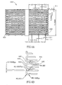
- Figs. 4A-4B are plan layouts of slit-type flow reducing implant 100.
- rim 402 is defined by sections 440 and 446. As shown, these sections are designed to provide a relative smooth rim, possibly with small amounts of distortion (so rim 402 remains smooth) where the sections connect to sections 442 and 444. Together, sections 442, 444 and 446 define outer slits for rim 402.
- Patients that are candidates for an angiogenesis-promoting procedure may have significant vascular compromise of the coronary circulation with constriction and/or lack of flow in one or more coronary arteries that supply blood to the coronary tissue.
- An invasive surgical procedure even to percutaneously introduce and/or position a reducing implant 100 into the coronary sinus, may trigger a cardiovascular accident with untoward sequella.
- averting and/or limiting the amount of time that the vasculature is invaded, for example, during use of a balloon catheter is desirable in some individuals.
- Figs. 4C-4D are a plan layout and isometric view, respectively of a slit-type flow reducing implant 1100 with a smooth rim.
- Slit-type flow-reducing implant 1100 comprises shape memory materials that automatically achieve a final configuration state upon exiting, for example, a delivery catheter or sheath, thereby averting the use of a balloon catheter for initial installation of slit-type flow-reducing implant 1100.
- a balloon expended material for example one that plastically deforms by expansion, may be used.
- Slit-type coronary flow-reducing implant 1100 shown in a plan view in Fig. 4C , contains preformed slits 1102, in accordance with an exemplary embodiment of the invention.
- Slits 1102 (and optionally a set of slits 1104 in a second or further row) define a row 1122 (and a row 1124) along an outer edge 1132 of slit-type flow-reducing implant 1100 that, in the unexpanded state comprise at least one edge 1132 that has a wavy configuration.
- edge 1132 becomes smooth while slits 1102 assume a rectangular appearance, with edge 1132 transverse to a slit 1138, for example.
- the slits of the rim are wider than the slits of the rest of implant 1100, thereby affecting its final expanded configuration.
- Slit-type coronary flow-reducing implant 1100 is transferred to its deployment site in coronary sinus using a guide sheath without accompaniment by a balloon catheter. As slit-type coronary flow-reducing implant 1100 reaches its destination and exits its guide sheath, coronary flow-reducing implant 1100 automatically expands into its final shape, shown in Fig. 4D . In this manner, slit-type coronary flow-reducing implant 1100 does not require manipulation and/or expansion using, for example, a balloon catheter.
- a balloon catheter may be used to facilitate expansion of slit-type flow-reducing implant 1100, for example, when it is made of materials that do not automatically attain a memorized shape.
- Rows 1122 and/or 1124 have lengths and/or orientations that promote flow-reducing implant 1100 to form into a final shape under pressure of a balloon catheter, therefore, installing with a minimal amount of time and/ or stress to the surrounding tissue.
- Slit-type coronary flow-reducing implant 1100 is designed to alter its shape in response to manipulation and/or expansion following installation. Slits 1138 expand so that a narrow passage 1168 automatically attains a first diameter during installation. Following installation of slit-type coronary flow-reducing implant 1100, a balloon catheter is introduced into narrow passage 1168 and inflated to press radially outward on narrow passage 1168. A pressure, for example, of between 7 and 8 atmospheres or less than 7 or greater than 8 atmospheres, depending, for example on the stiffness of the component materials, causes expansion slits 1138 to expand to a larger cross section. This causes narrow section 1168 to have a larger diameter than it had immediately following installation.
- slits 1138 may be oblique, thus possibly requiring a different degree of force to expand and/or providing a twisting of the deployed implant.
- Providing opposing oblique slits may be used to providing a shortening of the implant.
- flow-reducing implant 1100 When flow-reducing implant 1100 is installed, little or no blood migrates through the walls of narrow passage 1168 and/or a flare 1160 to contact the walls of the coronary sinus. This, for example, is achieved by a narrow configuration of the slits. Alternatively or additionally, the length of the slits decreases near narrowing 1168.
- the slits (e.g., not only slits 1102 and 1104 at the rim) are increased in number, while their width is reduced.
- the viscosity of the blood impedes its flow through the decreased width of the slits while the increased number of slits may foster expansion of implant 1100. This may result in a net reduction in blood flow through the implant walls.
- the slit width may be used to help define the device geometry. For example, slits (actually spaces) 1104 are wider than the other slits. If, for example, slits 1104 are made wider than slits 1102, a curved in rim may result.
- slits are arranged in alternating rows of long and short slits.
- the size and/or density of slits is larger near the rims than near the center of implant 1100.
- the length of the slits increases as a function of the distance from narrowing 1168.
- the material of implant 1100 is distorted by the expansion.
- the slits are distorted and the material is distorted to conform to these distortions.
- the short axial slit nearest the rim achieves a trapezoid rather than rectangular shape.
- the expanded configurations are idealized, with an actual expanded shape possibly including step-like distortions caused by the discrete pattern of the slits in the implant.
- Fig. 5 shows a vascular path to coronary sinus 102.
- flow reducing implant 100 is implanted using a trans-vascular approach, for example, from the venous system or by crossing through an intra-chamber wall in the heart.
- the delivery system is inserted through a jugular vein 510 or a subclavian vein 512 to a right atrium 506 of a heart 500 via a superior vena cava 508 and/or a femoral vein 502, via an inferior vena cava 504.
- the delivery system is guided (e.g., through a sharp bend) to an opening 514 into coronary sinus 102.
- a valve exists at the entrance to coronary sinus 102.
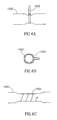
- Figs. 6A-6C are vise implants, 1000, 1010 and 1020, that reduce flow through a blood vessel 1002, and are applied from outside the blood vessel.
- Vise 1000 ( Fig. 6A ) is a band having any ratchet mechanism for preventing opening as known in the art; vise 1010 is a clip-like clasp; and vise 1020 is an elastic spiral.
- the band, clip and/or spiral are distortable.
- a balloon catheter can be inserted into the vessel and expanded, causing the spiral, clip and/or band to distort.
- the band comprises a plurality of slits (e.g., as in Fig. 8A ), that accommodate such distortion.
- Figs. 6D-6F show three exemplary clamps, 1030, 1040 and 1050, that reduce blood flow through vessel 1002.
- Clamp 1030 is a clip that shuts down part of the cross-section of vessel 1002; clamp 1040 is also a clip, that only distorts the cross-section of vessel 1002; and clamp 1050 is a tack (or suture) that transfixes a part of vessel 1002.
- Non-piercing clips are optionally designed to have rounded tip and/or non-meeting tips to reduce danger of piercing.
- Fig. 6G illustrates an exemplary endoscopic tool 1060 for releasing blood vessel reducing clasp 1010.
- Clasp 1010 is held between a flat plate 1064 and a Trans-axially movable arm 1062 with a broadened tip. Retracting arm 1062 towards tool 1060 causes the clasp to open and moving arm 1062 in a Trans-axial direction frees the clip.
- Various other clasp deployment mechanisms for plastic and elastic materials are known in the art and may be used.
- the procedure is performed through a key hole and using a working channel or a different keyhole to provide visual verification of the procedure. Alternatively or additionally, radiological verification may be provided.
- Various implants are known in the art for applying bands to blood vessel and may be used for the example of Fig. 6A as well.
- Flow-reducing implants 1000, 1010, 1020, 1030, 1040 and/or 1050 may be deployed on vessel 1002.
- these implants may be deployed onto tissue enclosing vessel 1002.
- the implant may be deployed onto (and/or piercing through) a pericardium and/or cardiac muscle tissue.
- Figs. 7A and 7B are a plan view and an isometric view of a flow reducing implant 1200 with anchors, in accordance with an exemplary embodiment of the invention.
- an anchor-type flow-reducing implant 1200 comprises at least one anchor 1202 that prevents motion of anchor-type flow-reducing implant 1200 in relation to a blood vessel.
- at least one anchor 1202 and/or 1204 are parallel to the blood vessel and catch on the tissue of the blood vessel to prevent displacement of anchor-type implant 1200. While the anchors are shown as flat, blunt and axial tabs, other designs may be used, for example, sharp, curled and/or oblique to the vessel axis.
- implant 1200 comprises one of row of anchors 1202 and/or row of anchors 1204 that prevent motion.
- anchors 1202 and/or 1204 are substantially parallel to the longitudinal axis of implant 1200 when it is in the non-expanded state and in the expanded state, shown in Fig. 7B .
- this parallel layout is achieved by the anchors being attached only to the rims and not the flaring section of the implant. thus, they tend to stay in the plane of the rim, which may be, for example parallel to the blood vessel wall or even pointing the anchors towards the wall (e.g., if the rim is curled in)
- anchor 1202 and/or 1204 are connected to anchor-type flow-reducing implant 1200 and protrude from its surface to into the surrounding tissue with a pressure sufficient to prevent motion of the implant without causing tissue irritation. This can be important in veins, for example, that have less thickness than comparable arteries.
- anchors that press with greater force or are pre-stressed to a greater non-parallel angle into the surrounding tissue may be desirable.
- anchor 1202 and/or 1204 are designed for such a vessel and press radially outward from the wall of anchor-type flow-reducing implant 1200, against the surrounding tissue.
- anchor-type flow-reducing implant 1200 includes anchors 1202 that have a free end that is not attached to narrow passage 1168 and, for example, blunt to avert tissue irritation.
- one or more deployed anchors 1202 are parallel to a longitudinal axis of anchor-type flow-reducing implant 1200, and point towards one or more anchors 1204.
- the vessels may form a lumen with an ellipsoid cross section.
- An anchor-type flow-reducing implant with anchors 1202 and/or 1204 that point toward one another may tend to migrate laterally and/or displace to one side of the other of the lumen.
- anchors 1202 and/or 1204 of anchor-type flow-reducing implant 1200 may be configured to compensate for not-cylindrical implantation environments.
- anchors 1202 and/or 1204 may be configured to point in a substantially perpendicular direction to longitudinal axis of anchor-type flow-reducing implant 1200, thus tending to prevent lateral movement of implant 1200.
- anchors 1202 may be connected to an edge 1232 and pointing away from anchors 1204 that are connected to an edge 1234. In this way, anchors 1202 and/or 1204 press into tissue at the edge of the implant that is stronger and/or exhibits a more uniform circumference.
- anchors 1202 and/or 1204 can be oriented in an oblique direction oblique to a transverse axis and/or longitudinal axis for example, to prevent migration in an environment where there is strong flow force of the blood stream that tends to exert force and displace implant 1200.
- anchors are shown cut out of the long slits, alternatively or additionally, the anchors may be cut out of short slits, for example a slit 1125.
- Fig. 8A is a portion of a plan layout of a section of a flow reducing implant 800 with selective narrowing control.
- Flow-reducing implant 800 includes a narrowed section 804.
- section 804 is also expandable, for example, having a plurality of thin slits 806 defined therein. This allows the minimum diameter of flow-reducing implant 800 to be increased after deployment.
- Section 804 is stiffer than the rest of flow-reducing implant 800, so that pressure suitable for expanding flow-reducing implant 800 will not expand section 804.
- flow-reducing implant 800 is a self-deploying implant and section 804 is plastically deformed using a balloon.
- a delivery system used for flow-reducing implant 800 may include both a restraining element and a balloon element. In case the implantation of a flow-reducing implant fails, extreme expansion of section 804 will substantially negate the function of flow-reducing implant 800 and may allow a new flow-reducing implant to be implanted within or through flow-reducing implant 800, at a later time.
- two sizes of slits 806 are provided, with the degree of resistance to deformation being determined by the sizes and/or relative sizes of the slits.
- Fig. 8B is a side cross-sectional view of a flow reducing implant 820 and a matching reducing catheter 840, which can be used to reduce the narrowing of implant 820.
- Flow-reducing implant 820 can be formed generally like flow-reducing implant 800, in that its narrowed section has a selectable diameter.
- Flow-reducing implant 820 includes a plurality of engagement points 822 that are adapted to be engaged by a plurality of engagers 846 of a catheter 840.
- engagement points 822 include a protruding arc 824 that is engaged by a barbed tip at engager 846.
- catheter 840 includes a body having a diameter similar to (or smaller, e.g., to allow for spring-back) the desired final diameter of flow-reducing implant 840.
- engagers 846 When engagers 846 are inserted adjacent to engagement points 822 and catheter 840 is rotated, the barbs engage the arcs.
- One or more wires 844 are retracted, retracting engagers 846 and arcs 824 towards catheter body 842.
- body 842 distorts barbs 846 so that they release arcs 824 so that catheter 840 can be removed.
- engagement/release mechanisms can be used, for example, barbs that match apertures in flow-reducing implant 820 or provision of grasping heads (e.g., pliers) at engagers 846.
- the narrowing procedure is performed under medical imaging, for example, fluoroscopy.
- Engagement means such as barbs 846 are used to remove the entire flow-reducing implant, optionally for replacement with a different flow-reducing implant and/or re-deployment of the same flow-reducing implant using a balloon on catheter 840 or after removal from the body.
- Flow-reducing implant 820 is a shape memory flow-reducing implant that expands when subjected to body temperature. A balloon having cool fluid circulating there through is brought into flow-reducing implant 820 to cause flow-reducing implant 820 to shrink back to an unexpanded configuration and/or be more amenable for removal.
- the decision to remove and/or change a diameter may be made only after a time period, during which vascular tissue may have grown into and attached onto flow-reducing implant 820.
- Fig. 8C is a two-part flow reducing implant 850 including a tubular section 852 and a reducing section 854.
- Reducing section 854 may be manufactured to match tubular section 852 or it may be a flow-reducing implant design as described herein or a flare, for example.
- tubular section 852 is optionally used to isolate reducing section 854 from the enclosing vascular tissue, thus allowing easier manipulation and/or replacement of section 854.
- the use of tubular section 852 may be desirable for prevention of damage to the vascular tissue.
- tubular section 852 is provided for other reasons, for example, to provide support for axial fixation of reducing section 854 and/or to reduce damage to a surrounding blood vessel.
- tubular section 852 and reducing section 854 may be of similar sizes or tubular section 852 may be considerably longer, for example, 25%, 50%, 100%, 200%, 400% or any smaller, intermediate or greater size ratio.
- the two sections may be inserted at the same time or at different procedures. The two sections may be inserted using a same delivery system or, for example, using two separate delivery systems.
- Tubular section 852 may be of various designs, for example, a coil or mesh stent, a stent graft, a graft with stents (or other attachment means) at its ends and/or a plain graft.
- Tubular section 852 and/or the tips of a flow-reducing implant may be made flexible and/or elastic to adapt to changes in blood vessel diameter.
- Fig. 8D is a flow reducing implant 860 including a narrowing insert to reduce the diameter of implant 860.
- Insert 870 has its expansion inside flow-reducing implant 860 limited by a narrowed diameter section 862 of flow-reducing implant 860.
- insert 870 has a funnel shape, with a narrow diameter opening 874 and a larger diameter opening 876.
- Insert 870 may be formed, for example, from a mesh and may be plastically, elastically, super-elastically and/or shape-memory deformed. The final geometry of insert 870 is defined by its resting points against flow-reducing implant 860.
- resting points comprise, for example, a point 864 generally between the narrow and flared sections of flow-reducing implant 860 and a resting point 866 on the flared section of flow-reducing implant 860.
- a ratchet mechanism is provided to anchor insert 870 in place.
- opening 874 is narrowed further (if required), by advancing opening 876 towards narrowed section 862 of flow-reducing implant 860.
- overcoming the ratchet mechanism and retracting opening 876 from section 862 enlarges opening 874.
- the ratchet mechanism comprises a plurality of inclined barbs or anchors 868, on flow-reducing implant 860.
- the ratchet mechanism and/or locking mechanism comprises a barb 872 on insert 870.
- a band or clip is applied to the outside of the enclosing blood vessel, urging flow-reducing implant 820 (e.g., at its narrow and/or broad sections) to close.
- the band is applied alone, without a flow-reducing implant.
- Exemplary bands and other implants are described in Fig. 6A-6G . Such implants may be used to plastically urge flow-reducing implant 820 closed, in which case, a pliers (optionally adapted to pass through a keyhole) may be used instead of a permanent clamp.
- the jaws of the pliers are optionally formed to have a cross-section matching desired cross-section of flow-reducing implant 820.
- flow-reducing implant 820 is elastic or super-elastic, and a permanent implant is implanted outside the blood vessel.
- the band or pliers is applied over a wide area, for example, 30%, 50%, 80% or any greater intermediate or smaller percentage of the length of flow-reducing implant 820, to reduce damage to the blood vessel.
- the narrowing effect is applied to a weakened part of flow-reducing implant 820, for example, a broad section thereof.
- flow of blood through slits 1125 may add to turbulence of blood flowing through flow-reducing implant 1100.
- Such turbulence may contribute to the formation of blood clots that cause embolitic sequella, for example a stroke, at distant locations in the body.
- flow-reducing implants with non slit walls may not exhibit appropriate expansion capabilities and/or facilitate in situ revision of its configuration.
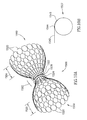
- Fig. 8E is an isometric view of a dual layer flow-reducing implant 1400.
- Dual layer flow-reducing implant 1400 comprises a first flared section 1450 and/or a second flared section 1460.
- first flared section 1450 and/or a second flared section 1460.
- second flared section 1460 For purposes of clarity, the components of flare 1460, alone, will be focused on, though similar features can be applied to flared section 1450.
- Dual layer flow-reducing implant 1400 comprises a flared section 1460 comprising an external cone 1410 and an internal cone 1420.
- Internal cone 1420 for example, comprises slits 1422 and 1426 and external cone 1410 comprises slits 1412 and 1416 so that cones 1410 and 1420 can be transported to an implantation site in a non-expanded state and expanded at the implantation site.
- cone 1410 and/or 1420 may be desirable and can be incorporated into their respective designs so that cone 1410 and/or 1420 expand to a first diameter when pressed radially outward by a balloon catheter at a first expansion pressure. Cone 1410 and/or 1420 can then expand to a second, greater, diameter when pressed radially outward by a balloon catheter at a second, greater, expansion pressure.
- flow-reducing implant 1400 may be implanted into a vessel with a relatively slow flow speed and/or low pressure.
- implantation in the coronary sinus narrow area 1440 may fill with tissue that aids in anchoring implant 1400 without risk of an embolism.
- a clot forms in area 1440 and stabilizes in its position. Stabilized clot in area 1440 becomes incorporated into the surrounding tissue and against dual cone flow-reducing implant 1400 so that it is further stabilized in its position.
- Slits 1422 and 1426 can be rotated, prior to implantation, in relation to slits 1412 and 1416 so that blood flow in direction 1451 is substantially stopped to various degrees.
- reducing implant 1400 may be implanted into a vessel with a relatively higher flow speed and/or higher pressure, for example a main trunk of an artery thereby protecting the patient against the dangers of embolism migration.
- the alignment of slits 1422 and 1426 is optionally set prior to implantation in a blood vessel in relation to slits 1412 and 1416, in order to establish a pre-defined blood flow pattern, and the two layers expanded or allowed to expand, together.
- cones 1410 and 1420 have, for example, a friction surface interface and/or interdigitation.
- the two layers may be deployed in different ways, for example, the inner layer may be plastically deployed and the outer layer self-deployed. Possibly, the profile of the two layers does not match along its entire length.
- the outer layer is plastically deformed by a self-deploying inner layer (which self deployment may also provide the friction for locking).
- cone 1420 may be rotated, for example using a suitable internal engaging catheter, after implantation
- the flared sections 1450 and 1460 need not be symmetric.
- the implant may also select between flow blockage at one section, the other and optionally both. Flow only into space 132, may assist in clot formation. Flow only out of space 132 may assist in collapsing a surrounding blood vessel.
- Figs. 9A-9G illustrate various flow-reducing implant variations. While a sigmoid-like flare is shown, a linear or other flared design may also be provided.
- Fig. 9A is a flow-reducing implant 900 with having a narrowed section 902 and a single flared section 904. Narrowed section 902 may point upstream or down stream.
- One potential advantage of this design is that the delivery system is less likely to get caught inside narrowed section 902.
- Another potential advantage is that a completely obstructing implant can be provided. However, even such a completely obstructing implant has smooth sides, to prevent damage to the coronary sinus. Possibly, the outer diameter of the completely obstructing implant or a nearly complete flow-reducing implant is increased beyond that of the coronary sinus, to prevent dislodgment of the implant Alternatively or additionally, one or more barbs on the outside of the implant may be provided.
- a cone shaped flow-reducing implant is provided with one or more openings for blood flow on the face of the cone, rather than at its apex as shown.
- the narrowing may be a valve, for example, a valve that opens, to a full or partial diameter, after a suitable pressure is achieved in the coronary sinus distal from the right atrium.
- a leaflet valve or other type of vascular valve as known in the heart may be provided.
- Fig. 9B shows an alternative flow-reducing implant 910; with two narrowed sections 912 and 916 sandwiching a flared section 914 between them.
- the different narrowed sections have a different inner diameter.
- the narrowed sections are selectively expanded using a balloon to achieve a desired pressure profile.
- Fig. 9C is an alternative flow-reducing implant 920 with three narrowed sections 922, 926 and 929 and two flared sections 924 and 928 between the narrowed sections.
- Certain blood vessels may exhibit a taper along their length, for example forming an angle 1310, shown in Fig. 9D . Vessels that change in size along their length may occur, for example, in the coronary sinus as it joins into the right atrium.
- a tapered blood vessel it may be desirable to utilize a tapered-type flow-reducing implant 930 ( Fig. 9E ), seen in detail in Fig. 9D .
- Fig. 9D is an isometric view of a tapered flow-reducing implant 1300, (with a similar configuration to implant 930).
- Tapered flow-reducing implant comprises a smaller flared section 1330, a narrowed section 1340 and larger flared section 1320.
- the size of smaller flared section 1330 is governed one or more slits 1342 that are transverse to the axis of narrowed section 1340 and one or more slits 1346 that are longitudinal to the axis of narrowed section 1340.
- the size of larger section 1320 is governed, for example, by two or more slits 1322 that are transverse to the axis of narrowed section 1340 and/or two or more slits 1326 that are longitudinal to the axis of narrowed section 1340.
- slits 1342, 1346, 1322 and/or 1326 be varied size and/or configuration to govern the shape of flared sections 1330 and/or 1320.
- slits 1342, 134b, 1322 and/or 1326 may have various arrangements to provide different contours to flared sections 1330 and/or 1330 and/or narrowed section 1340.
- openings 1330 and 1320 are shown as being round, they may have a variety of configurations to conform to different vessel configurations as noted above. Further, the ratio between opening 1330 and 1320 may be varied to conform to any vessel diameter where flow-reducing implant 1300 is implanted. As in other figures, the material of the implant is shown distorted, while in some implants, it may be the slits, possibly in addition to the material, which is distorted.
- Fig. 9E is a tapered flow-reducing implant 930 in which one flared section 932 has a smaller diameter than a second flared section 936, but larger than an intermediate narrowed section 934.
- Fig. 9F is a flow-reducing implant 940 that is not axially and/or rotationally symmetric around its axis.
- a first flared section 946 is distorted relative to an axis defined by a second flared section 942 and a narrowed section 944.
- flow-reducing implant 940 is curved.
- Asymmetric or curved flow-reducing implants include special markings, for example, radio-opaque or radio-transparent areas, to assist correct orientation of flow-reducing implant 940 in a blood vessel.
- Fig. 9G is a flow-reducing implant 950, in which a narrowed section 954 is a sleeve 954.
- Sleeve 954 for example, is formed of a flexible graft material, such as Dacron or GoreTex.
- Flow-reducing implant 950 further comprises at least one of two outer rings 952 and 956 that serve to anchor flow-reducing implant 950 in the blood vessel.
- a potential advantage of using a sleeve is that it can bend to conform to the vein geometry and/or dynamics. Other flow-reducing implant designs can also bend.
- the graft material is elastic, so it can serve as a pressure limiting valve, to better control coronary sinus pressure.
- a constraining ring is provided on the outside of section 954, to restrict the lumen of flow-reducing implant 950.
- the ring is placed on flow-reducing implant 950 during the procedure, to achieve a desired narrowing effect.
- the ring is expandable, for example using a balloon, to allow controlling the narrowed section of flow-reducing implant 950.
- the ring is sutured to narrowed section 954.
- section 954 is stiffened, for example, using a wire, as known in the art of stent-grafts.
- Flow-reducing implant 100 is provided in kit form, possibly with a delivery system, a flow-reducing implant diameter control system, additional flow-reducing implants, external bands and/or other means for reducing its inner diameter, and including instructions for use and/or size markings.
- flow-reducing implant 940 is provided inserted into a delivery system or packaged with a delivery system.
- a flow reducing implant is constrained by providing a band on the outside of the implant.
- Figs. 10A-10B are an isometric view and detail, respectively, of a ringed mesh-type flow reducing implant.
- Mesh-type flow-reducing implant 1500 ( FIG. 10A ) comprises a flare shoulder 1502 and/or a flare shoulder 1504 that are relatively long in length, for example, to increase the area of contact between flow-reducing implant 1500 and surrounding vessel walls.
- tissue may grow through the mesh of flare shoulders 1502 and/or 1504, providing good anchorage of mesh-type flow-reducing implant 1500.
- mesh-type flow-reducing implant 1500 comprises and/or is coated with materials that promote tissue ingrowth.
- a rim 1520 which may be, for example jagged or smooth is also optionally provided on each shoulder.
- the initial shape of mesh-type flow-reducing implant 1500 is governed by one or more bands 1522 and/or 1524 that constrict an area 1528 of mesh-type flow-reducing implant 1500.
- the surrounding tissue collapses onto mesh-type flow-reducing implant 1500 to reduce blood flow through the walls of constriction area 1528. While two bands 1522 and 1524 are shown, a single band, for example band 1522 alone, may be used to create constriction area 1528.
- a balloon catheter for example, is expanded in area 1562 to cause expansion of bands 1522 and/or 1524, thereby expanding area 1562 to increase blood flow there through. In this fashion, blood reduction through flow-reducing implant 1500 can be regulated prior to placement and/or following placement of flow-reducing implant 1500 in a blood vessel.
- Band 1524 rips when a large expansion force is placed against it.
- a balloon catheter is positioned inside area 1562 and expanded until the pressure exceeds that which is required to rip band 1524.
- band 1524 ripped, the area of mesh area 1562 directly under it expands so that area 1562 expands in diameter so that it has the diameter of ring 1522.
- band 1524 has a smaller diameter than band 1522, providing two levels of expansion. For example, so that as a balloon catheter is expanded to a first diameter, it expands smaller diameter band 1524, increasing the diameter of constriction area 1528 to a first expanded diameter. Should further increase in flow be desired, a balloon catheter is expanded to a second diameter and expands larger diameter band 1524 and/or smaller diameter band 1524, increasing the diameter of constriction area 1528 to a second expanded diameter.
- Ring 1524 has, for example, a diameter of 6 millimeters while ring 1522 has a diameter of 8 millimeters so that area 1562 has flow passage of 6 millimeters.
- area 1562 By expanding an expansion balloon inside area 1562 and causing ring 1524 to rip, the area under ring 1524 expands.
- ring 1522 With its diameter of 8 millimeters, maintains its integrity.
- area 1562 now has a flow passage of 8 millimeters (less the thickness of the mesh or other material from which the implant is formed.
- Fig. 10B is a detail of of ring 1522 comprising an adjustable band 1540 that forms ring 1522 and is held at a specific diameter by a clasp1544.
- adjustable band 1540 is maintained at a specific diameter by a clasp 1546.
- Clasps 1544 and/or 1546 hold adjustable band 1540 so that during implantation, ring 1522 remains at a specific diameter until, for example, an expanding balloon catheter is expanded against adjustable band 1540 and the diameter of ring 1522 is expanded.
- Clasps 1544 and 1546 comprise, for example, a nylon material that holds band 1522 at a specific diameter and allow expansion of the diameter only under expansion pressure from, for example, a balloon catheter.
- two clasps are provided, so no part of band 1540 sticks out from the ring.
- the clasps are "C" shaped and band 1540 optionally include bumps that prevent sliding of the band through the clasps. Alternatively or additionally, friction prevents such sliding.
- Flare shoulders 1504 and/or 1502 are 0.5 centimeters to 1 centimeter in length through they could be less than 0.5 centimeters or greater than 1 centimeter in length, for example, depending upon vessel configuration.
- Mesh-type flow-reducing implant 1500 comprises strands that form its mesh comprising gortex, Dacron and/or steel. Further, the material comprising the mesh can be configured to be flexible or rigid, depending, for example, on the materials, its thickness, based upon, for example the flow dynamic dynamics desired.
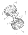
- Fig. 11 is an isometric view of a partially covered mesh-type flow reducing implant embodiment 1600.
- Mesh-type flow reducing implant 1600 comprises a covering 1614 over or inside narrow section 1624, implanted in a blood vessel 1680, shown in cross section.
- Mesh-type flow reducing implant 1600 comprises one or more flare shoulders 1602 that contact blood vessel 1680 to provide anchoring.
- a rim 1620 which may be, for example jagged or smooth is also optionally provided on each shoulder.
- mesh-type flow reducing implant 1600 comprises a covering 1614 the restricts blood flow through the surface of flow reducing implant 1600 and/or blood turbulence in an area of constriction 1624, thereby reducing danger of embolitic migration problems.
- Covering 1614 comprises a separate, flexible layer, that is attached to flow reducing implant 1600 at several points (e.g., at constriction area 1624 and/or flare shoulders 1602) to prevent tearing when implant 1600 expands. Prior to expansion, for example, covering 1614 is folded and/or pleated. Alternatively or additionally, covering 1614 has a low bulk and, for example, is integrated into flow reducing implant 1600 structure, for example, so that it substantially spans the open areas of the mesh. Examples of materials comprising covering 1614, include gortex, latex and/or silicone, on the inside and/or outside of flow reducing implant 1600.
- Fig. 12 is an isometric view of a sheath-type flow reducing implant 2340.
- Sheath-type flow reducing implant 2340 comprises a sheath 2342 that encircles at least a portion of outer wall 2102.
- Sheath-type flow reducing implant 2340 with a single sheath 2342 differs from implant 950 (shown Fig. 9G ) in which a narrowed section 954 is shown with two flared sides and supported by stents or rings 952 and/or 956.
- Connected to sheath 2342 and/or an extension thereof is a sheath projection 2352, with an opening 2354 to allow passage of blood flow via lumen 2216.
- Sheath projection 2352 can be configured with grooves and/or projections to further control the amount of obstruction of the central blood flow stream.
- Sheath 2342 includes a stiffener ring which maintains its opening patent.
- one or more stiffening axial or radial struts are provided to assist in maintaining the shape of sheath 2342.
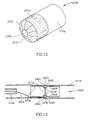
- Fig. 13 is longitudinal section of an inflatable tube-type flow reducing implant 2400.
- Inflatable tube-type flow reducing implant 2400 comprises a long wall 2406, a portion of which is surrounded by a ring-shaped tube 2420.
- tube 2420 can be located along any portion of long wall 2406 and/or of any configuration that reduces blood flow through lumen 2114.
- Tube 2420 replaces the function of ring 1522 of fig. 10A .
- Tube 2420 has an interior space 2430 enclosed within a circular wall 2402 that is, for example, inflatable using a hose 2428. Tube 2420 inflates so that interior 2430 has two or more cross sectional diameters, thereby allowing adjustment of narrow lumen 2114 to modify the amount of reduction in blood flow.
- Hose 2428 is optionally removed or torn off after deployment. Alternatively or additionally, hose 2428 may be attached after deployment, for example having a needle tip used tn inject fluid into tube 2420. Alternatively or additionally, tube 2420 may be tom or punctured after implantation, to increase the diameter of the narrowing.
- tube interior 2430 contains a material that absorbs liquid, thereby expanding. Following implantation, for example, tube 2420 absorbs liquid and interior 2430 increases in size until tube 2420 reaches its expanded state.
- wall 2402 and/or tube 2430 comprise a resilient material, for example Nitinol, and expand to a final state without inflation.
- flow-reducing implant 2400, and/or implants mentioned below are manufactured from a biocompatible material, comprising, for example, a soft silicone elastomer and/or another soft material such as latex, Teflon, gortex, Kevlar and/or polyurethane.
- interior 2430 is filled, for example with a spongy material, for example that is different from the material comprising long wall 2406 and/or wall 2402.
- Spongy material of interior 2430 for example, remains compressed in a compact size until its exit from catheter 2122 whereupon interior 2430 expands, causing the expansion of tube 2420.
- Long wall 2406 is contoured and comprises a shape memory material and achieves its final state, including a bulge 2404, upon exit from catheter 2122. Alternatively or additionally, long wall 2406 is, for example, not contoured and tube 2420 presses against long wall 2406 to create bulge 2404.
- Wall itself 2406 comprises a balloon, which is inflated.
- wall 2406 is manufactured with a varying thickness, for example being made of a flexible plastic cylinder with its top and bottom reamed out.
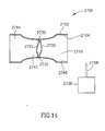
- Fig. 14 is a longitudinal section of a flow reducing implant with shape-conforming elements 2720.
- Shape-conforming element implant 2700 comprises one or more shape-conforming elements 2720 and/or 2722 that can be remotely induced to change their configuration. Remote control of the configuration of elements 2720 and/or 2722 causes, for example, change in configuration, constriction and/or expansion of narrow lumen 2742, flare 2744 and/or flare 2746 without associated hazards of an invasive procedure. As narrow lumen 2742, flare 2744 and/or flare 2746 change their configuration; the blood flow is obstructed to a greater or lesser extent, thereby promoting angiogenesis.
- Shape-conforming elements 2720 and/or 2722 are charged so that as they receive impulses from impulses 2730 and/or 2732, they change into one or more different geometric shapes and/or configurations.
- the shapes of elements 2720 and/or 2722 induced by impulsers 2730 and 2732 change the reduction in blood flow, thereby influencing angiogenesis.
- one or both shape-conforming elements 2720 and/or 2722 straighten, they exert outward expansion pressure on narrow lumen 2742, thereby allowing blood flow there through to increase.
- one or both shape-conforming elements 2720 and/or 2722 bend further than depicted in Fig. 14 they pull the walls of narrow lumen 2742 inward, causing lumen 2742 to narrow, thereby reducing blood flow there through.
- shape-conforming elements 2720 and/or 2722 bend or straighten wall 2102 along narrow lumen 2742 may change the obstruction of the lumen by wall 2102 to influence angiogenesis.
- shape-conforming elements 2720 and/or 2722 are located exterior to flow-reducing implant 2700, for example along outer wall 2102.
- other shape-conforming elements 2720 and/or 2722 may be located along flares 2744 and/or 2746 to provide additional and/or alternative remote control of flow-reducing implant 2700.
- impulsers 2730 and 2732 mediate a chemical reaction that modifies elements 2720 and/or 2722, thereby changing their configuration.
- a director 2738 external to the patient, directs impulsers 2730 and 2732 to provide impulses to shape-conforming elements 2720 and/or 2722, thereby causing the changes in geometric shape.
- Director 2738 directs impulsers 2730 and 2732 via radio waves from an antenna 2758.
- Impulses 2730 may be , for example ratchet mechanisms or motors powered or stimulated by such signals, to shorten bands that surround the implant.
- Impulsers 2730 comprise one or more magnetic motors that include a magnetic gear which is turned by the effect of a rotating magnetic field applied outside the body and which turning causes a tightening of a band (e.g., 2722, 2720).
- elements 2720 and/or 2722 are sensitive to waves that are propagated external to the patient.
- director 2738 provides one or more of: RF, acoustic waves such as ultrasound and/or low frequency sound, heat, electricity, electromagnetic and radiation to influence the configuration of elements 2720 and/or 2722.
- Impulsers 2730 and 2732 may then be optional, or be used only to provide a ratchet mechanism.
- Shape-conforming elements 2720 and/or 2722 comprise a material with a positive charge, for example positively charged plastic and/or silicone rubber. Alternatively or additionally, shape-conforming elements 2720 and/or 2722 comprise a negatively charged material.
- shape-conforming elements 2720 and/or 2722 are manufactured from a material comprising charged lithium ions.
- waves cause the charged lithium ions to align, thereby changing the geometry of shape-conforming elements 2720 and/or 2722 to cause changes in the shape of outer wall 2102 and/or inner wall 2104.
- impulsers 2730 and 2732 provide an electric impulse of between 0.1 volts and 0.5 volts (optionally, 0.1 volts or less or 0.5 volts or more), for a period of 10 msec or longer or 6 msec. or shorter.
- the factors influencing the impulse chosen, for example, depend upon materials comprising shape-conforming elements 2720 and/or 2722, their responsiveness to the impulses and/or the desired changes in their shapes to influence the shape of flow-reducing implant 2700.
- Flow-reducing implant 2700 with shape-conforming elements 2720 and/or 2722 allows modification in shape and/or blood flow reduction following implantation of flow-reducing implant 2700 in coronary sinus without an invasive procedure.
- a shape-conforming element implant 2700 that assumes its installed shape without, for example, the use of balloon catheter 1000 may be desirable.
- Externally applied RF radiation is received by threads 2722 and 2720, which act as antenna and heat up, thereby expanding.
- threads 2722 and 2720 act as antenna and heat up, thereby expanding.
- heating is used to inflate a balloon band, for example by causing an irreversible chemical reaction that releases gas.
- Fig. 15 is a plan layout of a cord-type flow reducing implant 2900.
- Cord-type flow-reducing implant 2900 comprises a preformed shape that will easily spring into its installed shape without, for example, use of balloon catheter. Alternatively, a balloon based expansion mechanism is provided.
- One or more edges 2910 are joined to one or more edges 2908 to form cord-type flow-reducing implant into a tubular shape with lumen passing there through.
- cord-type flow-reducing implant 2900 comprises a row of slits 2924 through which a cord 2954 passes, that is modified with minimal expansion pressure from balloon catheter.
- Cord 2954 is woven to pass under a lead post 2982 and over a trailing post 2986 so that cord 2954 is woven across cord-type flow-reducing implant 2900.
- cord 2954 is expandable and attached to surfaces of slots 2924, for example their surfaces facing lumen or their opposite (outside) surfaces.
- the cord blocks blood flow through the wall of the reducer.
- cord-type flow-reducing implant 2900 expands to its initial configuration automatically upon exiting a delivery sheath.
- a balloon catheter is introduced into the interior of cord-type flow-reducing implant 2900.
- the balloon catheter is inflated, for example, between 3-4 atmospheres (optionally, 3 atmospheres or less or 4 atmospheres or more), to cause cord 2954 to expand (or it may be loose) radially outward, thereby allowing slit 2958 to expand further and the diameter of the adjacent flared section to increase.
- an edge 2910 is detached from at least a portion of an edge and at least a portion edge 2910 and edge 2908 overlap.
- expansion force is applied, for example, between 7-8 atmospheres (optionally, 7 atmospheres or less or 8 atmospheres or more) is applied.
- Cord 2954 in response to the pressure, elongates (or is loose and tightens) so that edge 2910 draws closer and/or passes edge 2908, allowing cord-type flow-reducing implant 2900 to attain another, expanded, diameter.
- Cord 2958 comprises a plastic material that stretches to two or more lengths, depending upon the expansion pressure that is applied to it. Hence, at a lower pressure, cord 2954 expands to a first length, thereby defining a first narrow diameter of cord-type flow-reducing implant 2900. Subsequently a second expansion pressure is applied and cord 2954 attains a second, longer, length, thereby defining a second diameter, wider than the narrow diameter.
- cord-type flow-reducing implant 2900 includes one or more diameters in which edge 2910 and edge 2908 are separated by a space, thereby providing an interrupted lumen surface.
- cord 2954 severs upon application of, for example, pressure between 9-10 atmospheres (optionally 9 atmospheres or less or 10 atmospheres or more). Upon severing cord 2954, edge 2910, for example, maximally separates from edge 2908: thereby applying unrestricted pressure against coronary sinus.
- Cord 2954 of flow-reducing implant 2900 comprises a biocompatible material that dissolves in the environment of coronary sinus, for example, a material comprising galactic acid and/or polygalactic acid and/or other materials with similar properties.
- flow-reducing implant 2900 is placed in coronary sinus and the balloon catheter is used to expand it so that its outer surface contacts the inside surface of coronary sinus. Over a period of time, for example cord 2954 degrades, depending upon the biodissolvable material comprising cord 2954.
- cord 2954 occurs in less than three days or more than three days, dependent upon its composition and/or desired duty cycle.
- flow-reducing implant 2900 retains and/or assumes a shape with its outer surface in contact with the inner surface of coronary sinus.
- Flow-reducing implant 2900 comprises cord 2954 passing through slits 2924 and a cord 2964 passing through slots 2988.
- flow-reducing implant 2900 comprises three or more cords: 2954, 2964 at either end and a cord 2974 passing through slots 2926 substantially in the middle of flow-reducing implant 2900.
- Cords 2954, 2964 and/or 2974 serve to maintain the shape and/or appropriate lumen diameter following installation.
- balloon catheter is used to expand and/or sever cords 2954, 2964 and/or 2974.
- sever cords 2954,2964 and/or 2974 are biodissolvable, dissolving in the environment of coronary sinus.
- the final shape is that of a cone
- the relative lengths 2948, 2938 and 2928 of the slits 2946, 2936 (and 2934) and 2926, respectively, generally define the geometry of the expanded device.
- the cone shape is convex.
- other shapes, for example, concave may be provided instead.
- the slits are staggered, so that the expansion will be generally distributed over the surface of the implant.
- a flow reducing implant with similar design may also be used in other veins, for example, popliteal, tibial or saphenous veins.
- one or more flow reducing implants are implanted in popliteal veins, to increase back-pressure and possibly enhance tissue perfusion pressure and/or redistribute blood flow in the leg. It is expected that pooling will not occur due to the existence of alternative drainage paths in the leg. Multiple insertions of flow reducing implants may be used to treat and/or hide varicose veins.
- a plurality of thin-walled, valved venae comitantes are subjected to intermittent pressure both at rest and during exercise.
- the pulsation of the adjacent arteries help to move the blood up the limb.
- the contractions of the large muscles within the compartments during exercise compress these deeply placed veins and force the blood up the limb.
- the superficial saphenous veins lie within the superficial fascia and are not subject to these compression forces.
- the valves in the perforating veins which interconnect deep and surface veins, prevent the high-pressure venous blood from being forced outward into the low-pressure superficial veins.
- VAR venoarterial response
- neovascularization is considered an important cause of venous reflux recurrences after ligation of foot veins.
- the pathogenesis of this phenomenon is so far obscure.
- a hemodynamic factor could be the trigger initiating the process of neovascularization.
- Such a factor is provided in a form of increased pressure caused by reduction in vein diameter.
- the implantation of flow reducing implants in the veins is used to treat diabetic foot syndrome and/or varicose veins.
- the blood vessels treated include a lower limb vein, for example a superficial vein such as the great or small saphenous veins or their tributaries, or a limb deep vein such as the anterior and posterior tibial or popliteal veins, or a limb perforating vein, such as those in the region of the ankle and the medial side of the lower part of the leg.
- the degree of reducing and/or size of the flow reducing implant may be the same as used for the coronary sinus and/or be adapted to fit the particular vein being treated.
- the implantation procedure is as described above for the coronary sinus, except, of course, that the flow reducing implant is conveyed to a leg vein, rather than to the coronary sinus, for example, via a femoral vein.
- the flow reducing implant is implanted using a trans-vascular approach, for example, from the venous system.
- the delivery system is inserted through a femoral vein to a deep lower limb vein, such as the popliteal vein or tibial vein. Once in the deep foot vein, the delivery system is guided (e.g., through a sharp bend) to the vein.
- an open surgery approach may be used instead.
- a flow reducing implant is placed in a tibial vein and has a narrowing significant enough to encourage the formation of collateral circulation. It is hypothesized that collateral circulation is caused by an increase in venous blood pressure, which, in turn, increases the pressure in the capillaries and/or causes retro-flow in the capillaries and/or causes drainage of the capillaries.
- Alternative or additional hypotheses that are optionally used to select the constrictive effect of flow reducing implant include:
- flow reducing implant may be made to achieve one or more of the above suggested effects, optionally to a desired degree and/or taking into account safety issues, such as allowing some drainage and maximum pressure allowed by the venous drainage system. These effects may be determined using various measurements, such as a pressure sensor on the implanting catheter.
- the selection of the flow reducing implant depends on one or more of:
- the venous location of the flow reducing implant is selected to match various limb conditions, such as arterial blockage, alternatively or additionally to selecting the reducing diameter for each such flow reducing implant.
- the location(s) of implantation are selected to achieve a desired redistribution of lower limb artery pressures and/or blood flow, for example, to increase perfusion of ischemic or hibernating portions of the foot.
- the flow reducing implant implantation is combined with an arterial treatment, such as PCTA, stenosis removal (e.g., laser ablation) and/or stenting.
- the arterial treatment may be applied, for example, before, during or after the venous treatment, possibly during a same use of catheterization facilities.
- Doppler measurements are optionally used to asses leg perfusion.
- other perfusion and/or flow assessment methods may be used.
- an angiographic mapping is used before, during or after the procedure, for example to assist in determining what size flow reducing implant to use and/or a test obstruction of the lower limb vein. Such mapping may, for example, assist in determining a desired narrowing dimension of the flow reducing implant that will achieve a desired pressure increase and/or to detect possible side effects in the patient of such a pressure increase.
- the lower limb perfusion will increase and redistribution of blood flow will improve, even beyond the immediate result of the insertion of the flow reducing implant.
- the autonomic auto-regulation mechanism of the venous flow will be reset and/or restart. After a few months, revascularization is expected, in some cases, to be well established, and significantly improve the clinical picture.
- the flow reducing implant can be adapted to match other ducts or conduits in the body, for example, with respect to size, length, degree of narrowing, degree of elasticity and form of contact with the conduit walls.
- a flow reducing implant is used to reduce blood flow to a growth, for example a cancerous growth or other tumors.
- a first example in the treatment of tumors is the uterus.
- the myometrium inner lining of uterus
- the endometrial cavity is often the site of hyperplasia and neoplasia.
- Uterine Leiomyomas commonly known as fibroids or myomas, are well-circumscribed, benign tumors arising from the smooth muscle of the myometrium. They are composed of smooth muscle and extracellular matrix. Leiomyomas are the most common solid pelvic tumors in women. These are clinically apparent in 20% to 25% of women during the reproductive years, but careful pathologic inspection of the uterus reveals that they are present in more than 80% of women. Leiomyomas are characterized by their location in the uterus. Subserosal leiomyomas are located just under the uterine serosa and may be attached to the corpus by a narrow or a broad base.
- Intramural leiomyomas are found predominantly within the thick myometrium but may distort the cavity or cause an irregular external uterine contour.
- Submucous leiomyomas are located just under the uterine mucosa (endometrium).
- a known treatment is Uterine artery embolization in which small bubbles are freed in a supply vessel (e.g., a Uterine artery), causing embolisms in capillaries of the leiomyoma.
- the uterine artery is derived from the hypogastric anterior trunk. It crosses over the ureter at the level of the internal os of the cervix and divides into ascending and descending limbs.
- the ascending limb runs tortuously upward, between the leaves of the broad ligament, and supplies horizontal anterior and posterior branches to the cervix and the corpus.
- the descending branch of the uterine artery turns inferiorly and supplies the vagina from the lateral aspect. It anastomoses freely with the vaginal artery along its course.
- the ovarian arterial supply also has branches that anastomose with the ascending limb of the uterine artery.
- a leiomyoma is distinguished from healthy tissue by its degree of collateral vasculature and/or its sensitivity to ischemia.
- Uterine fibroid tumors are treated by implanting a flow reducing implant in selected uterine arteries, thus causing a reduction of the arterial blood supply of the uterine fibroid tumor, leading to ischemia and gradual necrosis of the tumor.
- the procedure is as follows. With the patient under mild intravenous sedation and local anesthesia, a small angiographic catheter is introduced into the femoral artery and guided into the left uterine artery. Arteriography is performed, determining the arteries diameter. A flow reducing implant is then inserted into the artery, causing a narrowing of its diameter. The process is optionally repeated in the right uterine artery. The flow reducing implant reduces arterial blood flow through the uterine arteries and causing ischemic necrosis. Normal myometrium is possibly unharmed because multiple collateral arteries supply it. After the right and left uterine arteries are catheterized, the catheter is removed, and the patient optionally undergoes standard post-arteriographic monitoring and recovery.
- the narrowed section reduces the vessel cross-section by 30%, 50%, 80%, 90% or any other lower, larger or intermediate amount, or even completely occludes the vessel.
- the narrowed section may have an inner diameter of 0.3 mm, 0.5 mm, 1 mm or any larger, smaller or intermediate size.
- a uterine procedure can be minimally invasive (e.g., using a laparoscope or a catheter), or be applied while performing other surgery.
- Another application is treating cancer.
- a viscous material is injected into a supply vessel of liver cancer, then a chemical poison is injected and then the vessel is sealed.
- a chemical poison is injected and then the vessel is sealed.
- the use of viscous material has various associated dangers, such as causing embolism in the brain and lungs.
- a flow reducing implant is used for treating cancer, especially cancer of the liver, for example, isolated liver metastases and for hepatocellular carcinoma and/or other tumors including HCC, colorectal, neuroendocrine, leiomyosarcoma, and melanoma metastases.
- Malignant tumors are treated by implanting a flow reducing implant in selected arteries that supply the malignant tumors, thus causing a significant reduction of arterial blood to the tumor, leading to tumor-cell hypoxia. This results in a controlled tumor regional ischemia and infarct and subsequent necrosis of tumors in the infarcted region.
- various chemical treatments such as known in the art are used as well.
- the liver is apparently especially amenable to this approach, due to the distinct lobular anatomy of the liver. Another potential factor is the existence of two independent blood supplies to the liver. A further potential factor is the ability of healthy hepatic tissue to compensate for tissue mass lost.
- a superselective catheter is inserted via a selected artery and threaded into the desired artery supplying the tumor, for example into the hepatic artery.
- Angiography is then performed to delineate the organ vasculature and performing various measurements, such as determining the diameter of the artery and measuring the required flow reducing implant diameter, followed by placement of the selected flow reducing implant.
- An angiographic study allows clear visualization of the hypervascular tumor, which is further studied by means of superselective catheterization.
- the catheter is removed, and the patient undergoes standard post-arteriographic monitoring and recovery.
- the method described may be used concurrently with an intraarterial infusion of antineoplastic agents mixed, for example, with iodized oil (Lipiodol (R)), which has been extensively used in the treatment of large HCC tumors, or combined with PEI (Percutaneous ethanol injection). It is expected that alcohol diffusion be easier after the occurrence of the hypoxic/necrotic changes produced by the implant, thus allowing the intranodular injection of larger amounts of ethanol. Moreover, after arterial embolization, the normal washout of the injected ethanol is more difficult in the tumorous area, resulting in potential longer retention of the substance.
- Various pharmaceuticals may be discharged by the flow reducing implant itself, as known, for example in the art of stents.
- the flow reducing implant may be coated with various pharmaceuticals or the flow reducing implant may include a dissolving portion or a reservoir.
- kits for example, kits that include sets of delivery systems and flow reducing implants.
- kits also include instructions for use. Measurements are provided to serve only as exemplary measurements for particular cases, the exact measurements applied will vary depending on the application.
- the terms "comprises”, “comprising”, “includes”, “including” or the like means “including but not limited to”.
Claims (10)
- Implant réducteur de flux (1200), comprenant :une section évasée (200 / 202) adaptée pour entrer en contact avec une paroi de vaisseau sanguin, ladite section évasée comprenant une première section (206 / 210) qui est inclinée par rapport à ladite paroi de vaisseau sanguin et une seconde section (212, 208) qui est généralement parallèle à ladite paroi de vaisseau sanguin ; etau moins une section rétrécie (204) continue avec ladite section évasée ; caractérisé en ce que ledit implant comprend au moins une languette d'ancrage (1202 / 1204) fixée sur ladite seconde section (212, 208) de ladite section évasée (200 / 202) adjacente à ladite première section (206 / 210), ladite au moins une languette d'ancrage (1202 / 1204) étant parallèle à un axe longitudinal dudit implant réducteur de flux (1200) lorsque ledit implant réducteur de flux (1200) est dans un état non expansé et dans un état expansé.
- Implant selon la revendication 1, dans lequel ledit implant est formé avec un matériau en feuille.
- Implant selon la revendication 2, dans lequel ladite au moins une languette d'ancrage (1202 / 1204) est découpée dans ladite première section (206 / 210) de sorte que lorsque ledit implant réducteur de flux est dans ledit état expansé, ladite au moins une languette d'ancrage (1202 / 1204) continue dans le même plan que ladite section évasée (200 / 202).
- Implant selon l'une quelconque des revendications 1 à 3, dans lequel ladite au moins une languette d'ancrage (1202 / 1204) est pointée vers ladite section rétrécie (204).
- Implant selon la revendication 1, comprenant au moins deux languettes d'ancrage opposées (1202 et 1204).
- Implant selon la revendication 1, comprenant au moins deux sections évasées (200 et 202), chacune avec au moins une languette d'ancrage (1202 et 1204).
- Implant selon la revendication 1, dans lequel ledit implant est plastiquement déformé dans ladite configuration.
- Implant selon la revendication 1, dans lequel ledit implant se déforme automatiquement dans ladite configuration.
- Implant selon la revendication 1, dans lequel ladite au moins une languette d'ancrage (1202 / 1204) est assez émoussée pour empêcher généralement l'endommagement dudit vaisseau sanguin.
- Implant selon l'une quelconque des revendications précédentes, dans lequel ladite section rétrécie (204) est configurée pour réduire le flux sanguin dans le vaisseau sanguin, afin d'encourager la formation de la circulation collatérale par rapport au vaisseau sanguin.
Applications Claiming Priority (5)
| Application Number | Priority Date | Filing Date | Title |
|---|---|---|---|
| IL14575001 | 2001-10-04 | ||
| IL14575001A IL145750A0 (en) | 2001-03-27 | 2001-10-04 | Narrowing implant |
| IL15116202A IL151162A0 (en) | 2002-08-08 | 2002-08-08 | Flow reducing implant |
| IL15116202 | 2002-08-08 | ||
| PCT/IL2002/000805 WO2003028522A2 (fr) | 2001-03-27 | 2002-10-03 | Implant reducteur de flux |
Publications (3)
| Publication Number | Publication Date |
|---|---|
| EP1450727A2 EP1450727A2 (fr) | 2004-09-01 |
| EP1450727A4 EP1450727A4 (fr) | 2007-02-28 |
| EP1450727B1 true EP1450727B1 (fr) | 2010-06-16 |
Family
ID=32510470
Family Applications (1)
| Application Number | Title | Priority Date | Filing Date |
|---|---|---|---|
| EP02772791A Expired - Lifetime EP1450727B1 (fr) | 2001-10-04 | 2002-10-03 | Implant reducteur de flux |
Country Status (12)
| Country | Link |
|---|---|
| US (6) | US20050055082A1 (fr) |
| EP (1) | EP1450727B1 (fr) |
| JP (1) | JP4398244B2 (fr) |
| AT (1) | ATE471124T1 (fr) |
| AU (1) | AU2002337598A1 (fr) |
| CA (5) | CA2462509A1 (fr) |
| DE (1) | DE60236755D1 (fr) |
| DK (1) | DK1450727T3 (fr) |
| ES (1) | ES2347770T3 (fr) |
| IL (1) | IL161278A (fr) |
| MX (1) | MXPA04003223A (fr) |
| WO (1) | WO2003028522A2 (fr) |
Families Citing this family (204)
| Publication number | Priority date | Publication date | Assignee | Title |
|---|---|---|---|---|
| US6953476B1 (en) * | 2000-03-27 | 2005-10-11 | Neovasc Medical Ltd. | Device and method for treating ischemic heart disease |
| IL153753A0 (en) * | 2002-12-30 | 2003-07-06 | Neovasc Medical Ltd | Varying-diameter vascular implant and balloon |
| US8038708B2 (en) * | 2001-02-05 | 2011-10-18 | Cook Medical Technologies Llc | Implantable device with remodelable material and covering material |
| JP4398244B2 (ja) | 2001-10-04 | 2010-01-13 | ネオヴァスク メディカル リミテッド | 流量減少インプラント |
| US7008397B2 (en) * | 2002-02-13 | 2006-03-07 | Percardia, Inc. | Cardiac implant and methods |
| US20030220661A1 (en) * | 2002-05-21 | 2003-11-27 | Heartstent Corporation | Transmyocardial implant delivery system |
| AU2003219503A1 (en) * | 2002-08-08 | 2004-02-25 | Neovasc Medical Ltd. | Geometric flow regulator |
| US20060106449A1 (en) * | 2002-08-08 | 2006-05-18 | Neovasc Medical Ltd. | Flow reducing implant |
| JP4081522B2 (ja) * | 2003-05-23 | 2008-04-30 | 新 石丸 | 一時留置型のステント及びステントグラフト |
| IL158960A0 (en) * | 2003-11-19 | 2004-05-12 | Neovasc Medical Ltd | Vascular implant |
| US7998220B2 (en) * | 2004-02-04 | 2011-08-16 | Murphy Timothy P | Methods for treating obesity |
| EP2308425B2 (fr) | 2004-03-11 | 2023-10-18 | Percutaneous Cardiovascular Solutions Pty Limited | Prothese de valvule cardiaque percutanee |
| US7641686B2 (en) * | 2004-04-23 | 2010-01-05 | Direct Flow Medical, Inc. | Percutaneous heart valve with stentless support |
| US7435257B2 (en) | 2004-05-05 | 2008-10-14 | Direct Flow Medical, Inc. | Methods of cardiac valve replacement using nonstented prosthetic valve |
| US20050278929A1 (en) * | 2004-06-16 | 2005-12-22 | National Taipei University Technology | Process of manufacturing stent with therapeutic function in the human body |
| US20050283226A1 (en) * | 2004-06-18 | 2005-12-22 | Scimed Life Systems, Inc. | Medical devices |
| US20060136042A1 (en) * | 2004-12-22 | 2006-06-22 | Scimed Life Systems, Inc. | Vulnerable plaque stent |
| CA2609022C (fr) * | 2005-05-20 | 2010-07-20 | The Cleveland Clinic Foundation | Appareil et methodes pour reparer la fonction d'une valve defectueuse et methode de fabrication de l'appareil |
| US9308359B2 (en) * | 2005-05-25 | 2016-04-12 | Boston Scientific Scimed, Inc. | Pull-through medical device |
| JP5119148B2 (ja) * | 2005-06-07 | 2013-01-16 | ダイレクト フロウ メディカル、 インク. | 半径方向の強度が高いステントレス大動脈弁置換 |
| DE102005032308A1 (de) * | 2005-07-11 | 2007-01-18 | Campus Gmbh & Co. Kg | Endovaskulares Implantat für den Verschluss eines Blutgefäßes |
| WO2007016251A2 (fr) * | 2005-07-28 | 2007-02-08 | Cook Incorporated | Valve thromboresistante implantable |
| US7301403B2 (en) * | 2005-09-10 | 2007-11-27 | Comlent Technology, Inc. | Low noise amplifier with switch gain control |
| AU2006315812B2 (en) | 2005-11-10 | 2013-03-28 | Cardiaq Valve Technologies, Inc. | Balloon-expandable, self-expanding, vascular prosthesis connecting stent |
| US20070213813A1 (en) * | 2005-12-22 | 2007-09-13 | Symetis Sa | Stent-valves for valve replacement and associated methods and systems for surgery |
| US8888800B2 (en) | 2006-03-13 | 2014-11-18 | Pneumrx, Inc. | Lung volume reduction devices, methods, and systems |
| US9402633B2 (en) | 2006-03-13 | 2016-08-02 | Pneumrx, Inc. | Torque alleviating intra-airway lung volume reduction compressive implant structures |
| US8157837B2 (en) | 2006-03-13 | 2012-04-17 | Pneumrx, Inc. | Minimally invasive lung volume reduction device and method |
| US7909789B2 (en) | 2006-06-26 | 2011-03-22 | Sight Sciences, Inc. | Intraocular implants and methods and kits therefor |
| US20080051879A1 (en) * | 2006-08-23 | 2008-02-28 | Cook Incorporated | Methods of treating venous valve related conditions with a flow-modifying implantable medical device |
| US7935144B2 (en) | 2006-10-19 | 2011-05-03 | Direct Flow Medical, Inc. | Profile reduction of valve implant |
| US8133213B2 (en) | 2006-10-19 | 2012-03-13 | Direct Flow Medical, Inc. | Catheter guidance through a calcified aortic valve |
| US9943409B2 (en) | 2006-11-14 | 2018-04-17 | The United States Of America, As Represented By The Secretary, Department Of Health And Human Services | Transcatheter coronary sinus mitral valve annuloplasty procedure and coronary artery and myocardial protection device |
| US8211171B2 (en) * | 2006-11-14 | 2012-07-03 | The United States Of America, As Represented By The Secretary Of The Department Of Health And Human Services | Transcatheter coronary sinus mitral valve annuloplasty procedure and coronary artery and myocardial protection device |
| EP2104468A2 (fr) * | 2007-01-08 | 2009-09-30 | Gross, Yossi | Filtre d'implantation in situ |
| US9656009B2 (en) | 2007-07-11 | 2017-05-23 | California Institute Of Technology | Cardiac assist system using helical arrangement of contractile bands and helically-twisting cardiac assist device |
| US20090088836A1 (en) * | 2007-08-23 | 2009-04-02 | Direct Flow Medical, Inc. | Translumenally implantable heart valve with formed in place support |
| US8764772B2 (en) * | 2008-02-21 | 2014-07-01 | Cook Medical Technologies Llc | Occlusion device |
| WO2009124247A2 (fr) * | 2008-04-03 | 2009-10-08 | William Cook Europe Aps | Dispositif d’occlusion |
| US9173669B2 (en) | 2008-09-12 | 2015-11-03 | Pneumrx, Inc. | Enhanced efficacy lung volume reduction devices, methods, and systems |
| EP2901966B1 (fr) | 2008-09-29 | 2016-06-29 | Edwards Lifesciences CardiAQ LLC | Valvule cardiaque |
| WO2010040009A1 (fr) | 2008-10-01 | 2010-04-08 | Cardiaq Valve Technologies, Inc. | Système de mise en place pour implant vasculaire |
| DK2361059T3 (da) * | 2008-11-24 | 2014-08-18 | Vascular Graft Solutions Ltd | Ekstern stent |
| US8414644B2 (en) | 2009-04-15 | 2013-04-09 | Cardiaq Valve Technologies, Inc. | Vascular implant and delivery system |
| CN102573700B (zh) | 2009-05-18 | 2014-12-17 | 纽姆克斯股份有限公司 | 细长的肺减容装置在部署过程中的横截面变化 |
| WO2011024159A2 (fr) * | 2009-08-24 | 2011-03-03 | Refael Hof | Matériaux à changement de phase et à changement de forme |
| US9730790B2 (en) | 2009-09-29 | 2017-08-15 | Edwards Lifesciences Cardiaq Llc | Replacement valve and method |
| US8870950B2 (en) | 2009-12-08 | 2014-10-28 | Mitral Tech Ltd. | Rotation-based anchoring of an implant |
| US20110144689A1 (en) * | 2009-12-15 | 2011-06-16 | Med Institute, Inc. | Occlusion Device |
| JP5856569B2 (ja) | 2010-02-05 | 2016-02-10 | サイト サイエンシーズ, インコーポレイテッド | 眼内圧を低減するためのデバイスと、それを含むキット |
| DE102010008362A1 (de) * | 2010-02-17 | 2011-08-18 | Transcatheter Technologies GmbH, 93053 | Medizinisches Implantat, welches aus einem nicht expandierten Zustand expandierbar ist |
| US20110224785A1 (en) * | 2010-03-10 | 2011-09-15 | Hacohen Gil | Prosthetic mitral valve with tissue anchors |
| US8579964B2 (en) | 2010-05-05 | 2013-11-12 | Neovasc Inc. | Transcatheter mitral valve prosthesis |
| US9247942B2 (en) | 2010-06-29 | 2016-02-02 | Artventive Medical Group, Inc. | Reversible tubal contraceptive device |
| WO2012002944A1 (fr) | 2010-06-29 | 2012-01-05 | Artventive Medical Group, Inc. | Réduction d'un écoulement à travers une structure tubulaire |
| US9125655B2 (en) * | 2010-07-16 | 2015-09-08 | California Institute Of Technology | Correction and optimization of wave reflection in blood vessels |
| US8992604B2 (en) | 2010-07-21 | 2015-03-31 | Mitraltech Ltd. | Techniques for percutaneous mitral valve replacement and sealing |
| US9763657B2 (en) | 2010-07-21 | 2017-09-19 | Mitraltech Ltd. | Techniques for percutaneous mitral valve replacement and sealing |
| US9132009B2 (en) | 2010-07-21 | 2015-09-15 | Mitraltech Ltd. | Guide wires with commissural anchors to advance a prosthetic valve |
| US11653910B2 (en) | 2010-07-21 | 2023-05-23 | Cardiovalve Ltd. | Helical anchor implantation |
| EP3459500B1 (fr) | 2010-09-23 | 2020-09-16 | Edwards Lifesciences CardiAQ LLC | Valvules cardiaques de remplacement et dispositifs |
| US9579193B2 (en) | 2010-09-23 | 2017-02-28 | Transmural Systems Llc | Methods and systems for delivering prostheses using rail techniques |
| US10321998B2 (en) | 2010-09-23 | 2019-06-18 | Transmural Systems Llc | Methods and systems for delivering prostheses using rail techniques |
| US9149277B2 (en) | 2010-10-18 | 2015-10-06 | Artventive Medical Group, Inc. | Expandable device delivery |
| US9566149B2 (en) * | 2010-11-16 | 2017-02-14 | W. L. Gore & Associates, Inc. | Devices and methods for in situ fenestration of a stent-graft at the site of a branch vessel |
| US9839540B2 (en) | 2011-01-14 | 2017-12-12 | W. L. Gore & Associates, Inc. | Stent |
| US10166128B2 (en) | 2011-01-14 | 2019-01-01 | W. L. Gore & Associates. Inc. | Lattice |
| CA2824284C (fr) | 2011-01-17 | 2020-10-27 | Novita Therapeutics, Llc | Dispositif a endoprothese a ballonnet et ses procedes d'utilisation |
| US11484318B2 (en) | 2011-01-17 | 2022-11-01 | Artio Medical, Inc. | Expandable body device and method of use |
| WO2012102919A1 (fr) * | 2011-01-24 | 2012-08-02 | Tufts Medical Center, Inc. | Endoprothèse vasculaire |
| US10864106B2 (en) | 2011-03-08 | 2020-12-15 | W. L. Gore & Associates, Inc. | Medical device for use with a stoma |
| US10052218B2 (en) | 2011-04-18 | 2018-08-21 | Vascular Graft Solutions Ltd. | Devices and methods for deploying implantable sleeves over blood vessels |
| US9554897B2 (en) | 2011-04-28 | 2017-01-31 | Neovasc Tiara Inc. | Methods and apparatus for engaging a valve prosthesis with tissue |
| US9308087B2 (en) | 2011-04-28 | 2016-04-12 | Neovasc Tiara Inc. | Sequentially deployed transcatheter mitral valve prosthesis |
| US8449565B2 (en) | 2011-07-21 | 2013-05-28 | Francis Duhay | Approaches to venous occlusion for embolus management |
| US8852272B2 (en) | 2011-08-05 | 2014-10-07 | Mitraltech Ltd. | Techniques for percutaneous mitral valve replacement and sealing |
| WO2013021375A2 (fr) | 2011-08-05 | 2013-02-14 | Mitraltech Ltd. | Remplacement et fixation percutanés d'une valvule mitrale |
| WO2013021374A2 (fr) | 2011-08-05 | 2013-02-14 | Mitraltech Ltd. | Techniques pour le remplacement et la fixation percutanés d'une valvule mitrale |
| US20140324164A1 (en) | 2011-08-05 | 2014-10-30 | Mitraltech Ltd. | Techniques for percutaneous mitral valve replacement and sealing |
| US9549817B2 (en) | 2011-09-22 | 2017-01-24 | Transmural Systems Llc | Devices, systems and methods for repairing lumenal systems |
| WO2013096548A1 (fr) * | 2011-12-23 | 2013-06-27 | Volcano Corporation | Procédés et appareil de régulation de pression sanguine |
| CA3049059C (fr) | 2012-01-17 | 2023-03-07 | Metactive Medical, Inc. | Dispositif corporel extensible et procede d'utilisation |
| ES2961369T3 (es) | 2012-03-20 | 2024-03-11 | Sight Sciences Inc | Sistemas de entrega ocular |
| US9345573B2 (en) | 2012-05-30 | 2016-05-24 | Neovasc Tiara Inc. | Methods and apparatus for loading a prosthesis onto a delivery system |
| CN108742951B (zh) * | 2012-06-06 | 2021-05-25 | 洋红医疗有限公司 | 人工肾脏瓣膜 |
| US9283072B2 (en) | 2012-07-25 | 2016-03-15 | W. L. Gore & Associates, Inc. | Everting transcatheter valve and methods |
| US9414752B2 (en) | 2012-11-09 | 2016-08-16 | Elwha Llc | Embolism deflector |
| US9931193B2 (en) | 2012-11-13 | 2018-04-03 | W. L. Gore & Associates, Inc. | Elastic stent graft |
| US9968443B2 (en) | 2012-12-19 | 2018-05-15 | W. L. Gore & Associates, Inc. | Vertical coaptation zone in a planar portion of prosthetic heart valve leaflet |
| US9101469B2 (en) | 2012-12-19 | 2015-08-11 | W. L. Gore & Associates, Inc. | Prosthetic heart valve with leaflet shelving |
| US9144492B2 (en) | 2012-12-19 | 2015-09-29 | W. L. Gore & Associates, Inc. | Truncated leaflet for prosthetic heart valves, preformed valve |
| US9681952B2 (en) | 2013-01-24 | 2017-06-20 | Mitraltech Ltd. | Anchoring of prosthetic valve supports |
| US8984733B2 (en) | 2013-02-05 | 2015-03-24 | Artventive Medical Group, Inc. | Bodily lumen occlusion |
| US9095344B2 (en) | 2013-02-05 | 2015-08-04 | Artventive Medical Group, Inc. | Methods and apparatuses for blood vessel occlusion |
| US10583002B2 (en) | 2013-03-11 | 2020-03-10 | Neovasc Tiara Inc. | Prosthetic valve with anti-pivoting mechanism |
| US10583231B2 (en) | 2013-03-13 | 2020-03-10 | Magenta Medical Ltd. | Blood pump |
| JP2016509950A (ja) | 2013-03-13 | 2016-04-04 | マジェンタ・メディカル・リミテッド | 腎臓ポンプ |
| US9730791B2 (en) | 2013-03-14 | 2017-08-15 | Edwards Lifesciences Cardiaq Llc | Prosthesis for atraumatically grasping intralumenal tissue and methods of delivery |
| US9681951B2 (en) | 2013-03-14 | 2017-06-20 | Edwards Lifesciences Cardiaq Llc | Prosthesis with outer skirt and anchors |
| US10660645B2 (en) | 2013-03-15 | 2020-05-26 | Embo Medical Limited | Embolization systems |
| US10905539B2 (en) * | 2013-03-15 | 2021-02-02 | W. L. Gore & Associates, Inc. | Self-expanding, balloon expandable stent-grafts |
| US9572665B2 (en) | 2013-04-04 | 2017-02-21 | Neovasc Tiara Inc. | Methods and apparatus for delivering a prosthetic valve to a beating heart |
| US9636116B2 (en) | 2013-06-14 | 2017-05-02 | Artventive Medical Group, Inc. | Implantable luminal devices |
| US9737306B2 (en) | 2013-06-14 | 2017-08-22 | Artventive Medical Group, Inc. | Implantable luminal devices |
| US9737308B2 (en) | 2013-06-14 | 2017-08-22 | Artventive Medical Group, Inc. | Catheter-assisted tumor treatment |
| US10149968B2 (en) | 2013-06-14 | 2018-12-11 | Artventive Medical Group, Inc. | Catheter-assisted tumor treatment |
| GB2516423B (en) | 2013-07-10 | 2015-07-15 | Cook Medical Technologies Llc | Vascular closure device |
| US10010328B2 (en) | 2013-07-31 | 2018-07-03 | NeuVT Limited | Endovascular occlusion device with hemodynamically enhanced sealing and anchoring |
| WO2015015314A2 (fr) * | 2013-07-31 | 2015-02-05 | EMBA Medical Limited | Procédés et dispositifs pour embolisation endovasculaire |
| US10842918B2 (en) | 2013-12-05 | 2020-11-24 | W.L. Gore & Associates, Inc. | Length extensible implantable device and methods for making such devices |
| CN110721009B (zh) | 2013-12-13 | 2022-01-11 | Vac 支架米德迪尔股份公司 | 用于密封泄漏的抽吸支架、支架系统和方法 |
| GB2522034B (en) | 2014-01-10 | 2015-12-02 | Cook Medical Technologies Llc | Implantable medical device with flexible connection |
| US10064719B2 (en) * | 2014-03-11 | 2018-09-04 | Highlife Sas | Transcatheter valve prosthesis |
| US20170014115A1 (en) | 2014-03-27 | 2017-01-19 | Transmural Systems Llc | Devices and methods for closure of transvascular or transcameral access ports |
| US10363043B2 (en) | 2014-05-01 | 2019-07-30 | Artventive Medical Group, Inc. | Treatment of incompetent vessels |
| US11439396B2 (en) | 2014-05-02 | 2022-09-13 | W. L. Gore & Associates, Inc. | Occluder and anastomosis devices |
| US9993251B2 (en) | 2014-05-02 | 2018-06-12 | W. L. Gore & Associates, Inc. | Anastomosis devices |
| US11712230B2 (en) | 2014-05-02 | 2023-08-01 | W. L. Gore & Associates, Inc. | Occluder and anastomosis devices |
| CN107072774B (zh) * | 2014-06-18 | 2019-09-06 | 波士顿科学国际有限公司 | 胆道支架 |
| US10667931B2 (en) * | 2014-07-20 | 2020-06-02 | Restore Medical Ltd. | Pulmonary artery implant apparatus and methods of use thereof |
| WO2016016899A1 (fr) | 2014-07-30 | 2016-02-04 | Mitraltech Ltd. | Prothèse valvulaire articulable |
| US10390838B1 (en) | 2014-08-20 | 2019-08-27 | Pneumrx, Inc. | Tuned strength chronic obstructive pulmonary disease treatment |
| US9827094B2 (en) | 2014-09-15 | 2017-11-28 | W. L. Gore & Associates, Inc. | Prosthetic heart valve with retention elements |
| CN104287878B (zh) * | 2014-09-16 | 2017-02-08 | 李宝童 | 血管腔内支架 |
| WO2016044647A2 (fr) | 2014-09-17 | 2016-03-24 | Metactive Medical, Inc. | Dispositif à corps dilatable et procédé d'utilisation |
| EP3226819B1 (fr) | 2014-11-25 | 2018-10-24 | New Phase Ltd. | Nanoparticule à changement de phase |
| US10166126B2 (en) * | 2014-12-08 | 2019-01-01 | Boston Scientific Scimed, Inc. | Inflatable balloon stent |
| CH710439A1 (de) * | 2014-12-18 | 2016-06-30 | Intellistent Ag | Einstellbarer mehrlumiger Stent. |
| US9974946B2 (en) * | 2015-04-07 | 2018-05-22 | NeuroTronik IP Holding (Jersey) Limited | Inflatable intravascular electrode supports for neuromodulation |
| GB2534194B (en) | 2015-01-16 | 2017-02-08 | Cook Medical Technologies Llc | Cone Expanding Collapsible Medical Device |
| US9974651B2 (en) | 2015-02-05 | 2018-05-22 | Mitral Tech Ltd. | Prosthetic valve with axially-sliding frames |
| CA3162308A1 (fr) | 2015-02-05 | 2016-08-11 | Cardiovalve Ltd. | Valvule prosthetique a chassis coulissants sur le plan axial |
| EP3256071A4 (fr) * | 2015-02-12 | 2018-10-17 | Hemodynamx-Technologies Ltd. | Implant aortique |
| WO2016154633A1 (fr) * | 2015-03-26 | 2016-09-29 | Boston Scientific Scimed, Inc. | Systèmes et procédés pour occlusion vasculaire |
| US10299958B2 (en) | 2015-03-31 | 2019-05-28 | Sight Sciences, Inc. | Ocular delivery systems and methods |
| US11291824B2 (en) | 2015-05-18 | 2022-04-05 | Magenta Medical Ltd. | Blood pump |
| US20170042551A1 (en) | 2015-08-13 | 2017-02-16 | The Brain Protection Company PTY LTD | Implantable damping devices for treating dementia and associated systems and methods of use |
| WO2017049003A1 (fr) | 2015-09-15 | 2017-03-23 | Nasser Rafiee | Dispositifs et des procédés permettant de réaliser des opérations glenn et fontan percutanées |
| EP3352686A1 (fr) * | 2015-09-24 | 2018-08-01 | NeuVT Limited | Dispositif d'occlusion neurovasculaire |
| EP3373828A1 (fr) * | 2015-11-09 | 2018-09-19 | Revamp Medical Ltd. | Réducteur de débit sanguin pour traitement cardiovasculaire |
| US10531866B2 (en) | 2016-02-16 | 2020-01-14 | Cardiovalve Ltd. | Techniques for providing a replacement valve and transseptal communication |
| US10973527B2 (en) * | 2016-03-11 | 2021-04-13 | Hemant Deshmukh | Low profile, self-expanding, blood flow resisting device |
| US10813644B2 (en) | 2016-04-01 | 2020-10-27 | Artventive Medical Group, Inc. | Occlusive implant and delivery system |
| CA3021860C (fr) | 2016-04-21 | 2021-06-08 | W. L. Gore & Associates, Inc. | Endoprotheses diametralement reglables, systemes et procedes associes |
| US11007059B2 (en) | 2016-05-06 | 2021-05-18 | Transmural Systems Llc | Annuloplasty procedures, related devices and methods |
| KR102654995B1 (ko) | 2016-05-06 | 2024-04-04 | 더 유나이티드 스테이츠 오브 어메리카, 애즈 리프리젠티드 바이 더 세크러테리, 디파트먼트 오브 헬쓰 앤드 휴먼 서비씨즈 | 고리성형술 절차들, 관련된 기기들 및 방법들 |
| US11039923B2 (en) | 2016-05-06 | 2021-06-22 | Transmural Systems Llc | Annuloplasty procedures, related devices and methods |
| US10448938B2 (en) | 2016-06-16 | 2019-10-22 | Phillips Medical, LLC | Methods and systems for sealing a puncture of a vessel |
| US10350062B2 (en) | 2016-07-21 | 2019-07-16 | Edwards Lifesciences Corporation | Replacement heart valve prosthesis |
| US10856975B2 (en) | 2016-08-10 | 2020-12-08 | Cardiovalve Ltd. | Prosthetic valve with concentric frames |
| USD800908S1 (en) | 2016-08-10 | 2017-10-24 | Mitraltech Ltd. | Prosthetic valve element |
| WO2018029688A1 (fr) | 2016-08-12 | 2018-02-15 | Hemodynamx-Technologies Ltd | Implant aortique. |
| WO2018049111A1 (fr) * | 2016-09-09 | 2018-03-15 | W. L. Gore & Associates, Inc. | Concept d'arc total |
| US11771434B2 (en) * | 2016-09-28 | 2023-10-03 | Restore Medical Ltd. | Artery medical apparatus and methods of use thereof |
| US11039915B2 (en) | 2016-09-29 | 2021-06-22 | Magenta Medical Ltd. | Blood vessel tube |
| CN110049792B (zh) | 2016-11-23 | 2022-01-18 | 马真塔医药有限公司 | 血泵 |
| CN110520083B (zh) * | 2017-03-06 | 2022-03-29 | 心血管实验室股份公司和布雷维蒙特 Cv 实验室股份公司 | 多层管腔内假体及其制造方法 |
| US11724075B2 (en) * | 2017-04-18 | 2023-08-15 | W. L. Gore & Associates, Inc. | Deployment constraining sheath that enables staged deployment by device section |
| US10624620B2 (en) | 2017-05-12 | 2020-04-21 | Phillips Medical, LLC | Systems and methods for sealing a puncture of a vessel |
| US10716551B2 (en) | 2017-05-12 | 2020-07-21 | Phillips Medical, LLC | Systems and methods for sealing a puncture of a vessel |
| EP3624704A4 (fr) | 2017-06-05 | 2021-03-10 | Restore Medical Ltd | Appareil de type endoprothèse à longueur fixe à double paroi et ses procédés d'utilisation |
| GB2598251B (en) | 2017-06-28 | 2022-05-25 | Cook Medical Technologies Llc | Implantable medical device including valve member |
| US11246704B2 (en) | 2017-08-03 | 2022-02-15 | Cardiovalve Ltd. | Prosthetic heart valve |
| US10888421B2 (en) | 2017-09-19 | 2021-01-12 | Cardiovalve Ltd. | Prosthetic heart valve with pouch |
| US11793633B2 (en) | 2017-08-03 | 2023-10-24 | Cardiovalve Ltd. | Prosthetic heart valve |
| US10537426B2 (en) | 2017-08-03 | 2020-01-21 | Cardiovalve Ltd. | Prosthetic heart valve |
| US10575948B2 (en) | 2017-08-03 | 2020-03-03 | Cardiovalve Ltd. | Prosthetic heart valve |
| KR20200051661A (ko) | 2017-08-26 | 2020-05-13 | 트랜스뮤럴 시스템스 엘엘씨 | 심장 고리성형술 및 조율 시술, 그리고 관련 장치 및 방법 |
| US10595874B2 (en) | 2017-09-21 | 2020-03-24 | W. L. Gore & Associates, Inc. | Multiple inflation endovascular medical device |
| CA3178271A1 (fr) | 2017-09-27 | 2019-04-04 | W.L. Gore & Associates, Inc. | Valvule prothetique a cadre extensible et systemes et procedes associes |
| EP3634259B1 (fr) * | 2017-10-03 | 2024-02-14 | Boston Scientific Scimed, Inc. | Stent à régulation de débit |
| US11406801B2 (en) | 2017-10-27 | 2022-08-09 | Transit Scientific, LLC | Exoskeleton device with expandable section for scoring |
| EP3700441A4 (fr) | 2017-10-27 | 2021-07-28 | Transit Scientific, LLC | Dispositif d'exosquelette à section expansible permettant une incision |
| AU2018362079B2 (en) | 2017-10-31 | 2021-09-16 | Edwards Lifesciences Corporation | Medical valve and leaflet promoting tissue ingrowth |
| GB201718299D0 (en) * | 2017-11-03 | 2017-12-20 | Ab Wasstand Dev | Stents |
| EP3709932A4 (fr) | 2017-11-15 | 2021-08-11 | Hemodynamx-Technologies Ltd | Appareil et méthodes de réduction de perte de pression aortique |
| GB201720803D0 (en) | 2017-12-13 | 2018-01-24 | Mitraltech Ltd | Prosthetic Valve and delivery tool therefor |
| GB201800399D0 (en) | 2018-01-10 | 2018-02-21 | Mitraltech Ltd | Temperature-control during crimping of an implant |
| EP3720390B1 (fr) | 2018-01-25 | 2024-05-01 | Edwards Lifesciences Corporation | Système de distribution pour recapture de valvule de remplacement assistée et post-déploiement de repositionnement |
| US10893927B2 (en) | 2018-03-29 | 2021-01-19 | Magenta Medical Ltd. | Inferior vena cava blood-flow implant |
| AU2019242546B2 (en) * | 2018-03-29 | 2020-12-03 | Boston Scientific Scimed, Inc. | Flow control valve |
| EP3793490A4 (fr) * | 2018-05-12 | 2021-10-06 | Venacore Inc. | Régulation de la vitesse du flux sanguin vers l'oreillette droite |
| ES2755223R2 (es) * | 2018-06-26 | 2020-06-17 | Servicio Andaluz De Salud | Dispositivo para el tratamiento del aneurisma de aorta |
| US11382632B2 (en) * | 2018-06-27 | 2022-07-12 | Boston Scientific Scimed, Inc. | Vascular occlusion device |
| CN112469365A (zh) * | 2018-07-24 | 2021-03-09 | W.L.戈尔及同仁股份有限公司 | 用于流体流控制的可植入医疗设备 |
| US11723783B2 (en) | 2019-01-23 | 2023-08-15 | Neovasc Medical Ltd. | Covered flow modifying apparatus |
| MX2021009918A (es) * | 2019-02-17 | 2022-06-24 | Aorto Medical LLC | Injerto de stent de restriccion de flujo. |
| US11497601B2 (en) | 2019-03-01 | 2022-11-15 | W. L. Gore & Associates, Inc. | Telescoping prosthetic valve with retention element |
| EP3934592A1 (fr) * | 2019-04-17 | 2022-01-12 | W.L. Gore & Associates, Inc. | Dispositif et procédé de traitement aigu d'une surcharge de fluide chez des patients présentant une insuffisance cardiaque |
| CN110584734B (zh) * | 2019-08-19 | 2023-06-27 | 中国人民解放军总医院第八医学中心 | 治疗脾功能亢进症的血管内限流器及其制作方法 |
| CN110522485B (zh) * | 2019-08-27 | 2020-12-11 | 浙江大学 | 一种可降解的肠道完全转流支架 |
| US11504270B1 (en) | 2019-09-27 | 2022-11-22 | Sight Sciences, Inc. | Ocular delivery systems and methods |
| CN114641261A (zh) | 2019-10-30 | 2022-06-17 | 安吉美德医疗技术有限公司 | Tips支架移植物及套件 |
| KR20210052744A (ko) * | 2019-10-31 | 2021-05-11 | 주식회사 삼양바이오팜 | 비혈관용 스텐트 |
| EP4093324A1 (fr) | 2020-01-20 | 2022-11-30 | Angiomed GmbH & Co. Medizintechnik KG | Endoprothèse couverte et kit |
| US11471264B2 (en) * | 2020-04-01 | 2022-10-18 | Medtronic Vascular, Inc. | Branching stent graft with mechanical interlock |
| WO2021212011A2 (fr) * | 2020-04-16 | 2021-10-21 | Shifamed Holdings, Llc | Dispositifs interauriculaires réglables, et systèmes et méthodes associés |
| CA3176834A1 (fr) * | 2020-05-04 | 2021-11-11 | Marwan BERRADA-SOUNNI | Modulateur de pression et de flux vasculaire |
| WO2021230830A1 (fr) * | 2020-05-13 | 2021-11-18 | Mehmet Hakan Akpinar | Régulateur de débit dynamique contre l'insuffisance cardiaque |
| US11628052B2 (en) * | 2020-05-13 | 2023-04-18 | Jt Godfrey, Llc | Device for use with body tissue sphincters |
| US11938022B2 (en) | 2020-06-26 | 2024-03-26 | Highlife Sas | Transcatheter valve prosthesis and method for implanting the same |
| US20220287831A1 (en) * | 2021-03-12 | 2022-09-15 | Troy Thornton | Device and method for variable blood flow occlusion |
| WO2023150333A2 (fr) | 2022-02-04 | 2023-08-10 | VahatiCor, Inc. | Systèmes, dispositifs et procédés d'occlusion de sinus coronaire |
| WO2024039381A1 (fr) | 2022-08-19 | 2024-02-22 | Neovasc Medical Ltd. | Cathéter de guidage pour dispositif de modification d'écoulement |
Family Cites Families (261)
| Publication number | Priority date | Publication date | Assignee | Title |
|---|---|---|---|---|
| US565558A (en) * | 1896-08-11 | Car-fender | ||
| US3620218A (en) * | 1963-10-31 | 1971-11-16 | American Cyanamid Co | Cylindrical prosthetic devices of polyglycolic acid |
| US3334629A (en) * | 1964-11-09 | 1967-08-08 | Bertram D Cohn | Occlusive device for inferior vena cava |
| GB1264471A (fr) | 1968-01-12 | 1972-02-23 | ||
| GB1315844A (en) | 1970-05-12 | 1973-05-02 | Nat Res Dev | Prosthetic cardiac valve |
| US3739402A (en) | 1970-10-15 | 1973-06-19 | Cutter Lab | Bicuspid fascia lata valve |
| AR206762A1 (es) | 1976-01-01 | 1976-08-13 | Pisanu A | Bioprotesis de bajo perfil derivada de la valvula aortica heterologa de porcino |
| CA1069652A (fr) * | 1976-01-09 | 1980-01-15 | Alain F. Carpentier | Valvule prosthetique avec anneau deformable |
| US4047252A (en) | 1976-01-29 | 1977-09-13 | Meadox Medicals, Inc. | Double-velour synthetic vascular graft |
| US4297749A (en) * | 1977-04-25 | 1981-11-03 | Albany International Corp. | Heart valve prosthesis |
| GB1603634A (en) | 1977-05-05 | 1981-11-25 | Nat Res Dev | Prosthetic valves |
| US4292974A (en) * | 1980-01-30 | 1981-10-06 | Thomas J. Fogarty | Dilatation catheter apparatus and method |
| US4340977A (en) | 1980-09-19 | 1982-07-27 | Brownlee Richard T | Catenary mitral valve replacement |
| US4339831A (en) | 1981-03-27 | 1982-07-20 | Medtronic, Inc. | Dynamic annulus heart valve and reconstruction ring |
| US4470157A (en) | 1981-04-27 | 1984-09-11 | Love Jack W | Tricuspid prosthetic tissue heart valve |
| US4865600A (en) | 1981-08-25 | 1989-09-12 | Baxter International Inc. | Mitral valve holder |
| EP0084395B1 (fr) | 1982-01-20 | 1986-08-13 | Martin Morris Black | Valvules cardiaques artificielles |
| US4501263A (en) * | 1982-03-31 | 1985-02-26 | Harbuck Stanley C | Method for reducing hypertension of a liver |
| US4494531A (en) | 1982-12-06 | 1985-01-22 | Cook, Incorporated | Expandable blood clot filter |
| US4546499A (en) * | 1982-12-13 | 1985-10-15 | Possis Medical, Inc. | Method of supplying blood to blood receiving vessels |
| US4727873A (en) * | 1984-04-17 | 1988-03-01 | Mobin Uddin Kazi | Embolus trap |
| US4705517A (en) * | 1985-09-03 | 1987-11-10 | Becton, Dickinson And Company | Percutaneously deliverable intravascular occlusion prosthesis |
| US5622713A (en) * | 1985-09-17 | 1997-04-22 | The Regents Of The University Of California | Method of detoxifying animal suffering from overdose |
| US4733665C2 (en) * | 1985-11-07 | 2002-01-29 | Expandable Grafts Partnership | Expandable intraluminal graft and method and apparatus for implanting an expandable intraluminal graft |
| CH668192A5 (de) * | 1985-11-29 | 1988-12-15 | Schneider Medintag Ag | Katheter zur behandlung von verengten stellen, beispielsweise in einem blutgefaess. |
| US4893623A (en) * | 1986-12-09 | 1990-01-16 | Advanced Surgical Intervention, Inc. | Method and apparatus for treating hypertrophy of the prostate gland |
| US4813934A (en) * | 1987-08-07 | 1989-03-21 | Target Therapeutics | Valved catheter device and method |
| US5100420A (en) * | 1989-07-18 | 1992-03-31 | United States Surgical Corporation | Apparatus and method for applying surgical clips in laparoscopic or endoscopic procedures |
| IT1225673B (it) | 1988-07-22 | 1990-11-22 | Luigi Bozzo | Dispositivo disostruttore per l'impiego nella patologia ostruttiva urinaria del maschio e strumento introduttore-estrattore del dispositivo stesso |
| US6730105B2 (en) * | 1988-07-29 | 2004-05-04 | Samuel Shiber | Clover leaf shaped tubular medical device |
| US5749915A (en) * | 1988-08-24 | 1998-05-12 | Focal, Inc. | Polymeric endoluminal paving process |
| US4994066A (en) * | 1988-10-07 | 1991-02-19 | Voss Gene A | Prostatic stent |
| FR2642960B1 (fr) | 1989-02-15 | 1994-02-25 | Dassault Breguet Aviation | Valve cardiaque prothetique |
| US5007926A (en) * | 1989-02-24 | 1991-04-16 | The Trustees Of The University Of Pennsylvania | Expandable transluminally implantable tubular prosthesis |
| DE69016426T2 (de) * | 1989-05-31 | 1995-08-17 | Baxter Int | Biologische klappenprothese. |
| DE3918736C2 (de) | 1989-06-08 | 1998-05-14 | Christian Dr Vallbracht | Kunststoffüberzogene Metallgitterstents |
| DE9010130U1 (fr) * | 1989-07-13 | 1990-09-13 | American Medical Systems, Inc., Minnetonka, Minn., Us | |
| ATE120377T1 (de) | 1990-02-08 | 1995-04-15 | Howmedica | Aufblasbarer dilatator. |
| IL94138A (en) * | 1990-04-19 | 1997-03-18 | Instent Inc | Device for the treatment of constricted fluid conducting ducts |
| US5129902A (en) * | 1990-04-20 | 1992-07-14 | Marlowe Goble E | Endosteal ligament retainer and process |
| US5078736A (en) * | 1990-05-04 | 1992-01-07 | Interventional Thermodynamics, Inc. | Method and apparatus for maintaining patency in the body passages |
| DK124690D0 (da) * | 1990-05-18 | 1990-05-18 | Henning Rud Andersen | Klapprotes til implantering i kroppen for erstatning af naturlig klap samt kateter til brug ved implantering af en saadan klapprotese |
| GB9012716D0 (en) | 1990-06-07 | 1990-08-01 | Frater Robert W M | Mitral heart valve replacements |
| DE4018525C2 (de) * | 1990-06-09 | 1994-05-05 | Kaltenbach Martin | Katheter mit einem aufweitbaren Bereich |
| EP0461791B1 (fr) | 1990-06-11 | 1997-01-02 | Hector D. Barone | Greffe d'aorte et appareil pour la réparation d'un anévrisme de l'aorte abdominale |
| US5064435A (en) * | 1990-06-28 | 1991-11-12 | Schneider (Usa) Inc. | Self-expanding prosthesis having stable axial length |
| DE9014230U1 (fr) | 1990-10-13 | 1991-11-21 | Angiomed Ag, 7500 Karlsruhe, De | |
| DE69116130T2 (de) | 1990-10-18 | 1996-05-15 | Ho Young Song | Selbstexpandierender, endovaskulärer dilatator |
| US5380316A (en) * | 1990-12-18 | 1995-01-10 | Advanced Cardiovascular Systems, Inc. | Method for intra-operative myocardial device revascularization |
| US5397351A (en) * | 1991-05-13 | 1995-03-14 | Pavcnik; Dusan | Prosthetic valve for percutaneous insertion |
| ES2127756T3 (es) * | 1991-06-17 | 1999-05-01 | Wilson Cook Medical Inc | Dispositivo de extraccion endoscopica con una estructura filar metalica compuesta. |
| US5304220A (en) * | 1991-07-03 | 1994-04-19 | Maginot Thomas J | Method and apparatus for implanting a graft prosthesis in the body of a patient |
| US5222980A (en) * | 1991-09-27 | 1993-06-29 | Medtronic, Inc. | Implantable heart-assist device |
| US5304194A (en) * | 1991-10-02 | 1994-04-19 | Target Therapeutics | Vasoocclusion coil with attached fibrous element(s) |
| US5876445A (en) * | 1991-10-09 | 1999-03-02 | Boston Scientific Corporation | Medical stents for body lumens exhibiting peristaltic motion |
| US5662713A (en) * | 1991-10-09 | 1997-09-02 | Boston Scientific Corporation | Medical stents for body lumens exhibiting peristaltic motion |
| US5354309A (en) * | 1991-10-11 | 1994-10-11 | Angiomed Ag | Apparatus for widening a stenosis in a body cavity |
| US5211658A (en) | 1991-11-05 | 1993-05-18 | New England Deaconess Hospital Corporation | Method and device for performing endovascular repair of aneurysms |
| US5489297A (en) | 1992-01-27 | 1996-02-06 | Duran; Carlos M. G. | Bioprosthetic heart valve with absorbable stent |
| US5209727A (en) * | 1992-01-29 | 1993-05-11 | Interventional Technologies, Inc. | Guide wire with integral angioplasty balloon |
| US5405377A (en) | 1992-02-21 | 1995-04-11 | Endotech Ltd. | Intraluminal stent |
| FR2688688A1 (fr) | 1992-03-12 | 1993-09-24 | Richard Thierry | Outil de mise en place d'une endoprothese autoexpansible pour organe tubulaire humain ou animal. |
| FR2688401B1 (fr) * | 1992-03-12 | 1998-02-27 | Thierry Richard | Endoprothese expansible pour organe tubulaire humain ou animal, et outil de mise en place. |
| US5282823A (en) * | 1992-03-19 | 1994-02-01 | Medtronic, Inc. | Intravascular radially expandable stent |
| US5201757A (en) * | 1992-04-03 | 1993-04-13 | Schneider (Usa) Inc. | Medial region deployment of radially self-expanding stents |
| FR2689388B1 (fr) | 1992-04-07 | 1999-07-16 | Celsa Lg | Filtre sanguin perfectionne eventuellement resorbable. |
| WO1993022986A1 (fr) | 1992-05-08 | 1993-11-25 | Schneider (Usa) Inc. | Extenseur ×sophagien et outil d'introduction |
| US5772668A (en) * | 1992-06-18 | 1998-06-30 | American Biomed, Inc. | Apparatus for placing an endoprosthesis |
| US5382261A (en) * | 1992-09-01 | 1995-01-17 | Expandable Grafts Partnership | Method and apparatus for occluding vessels |
| US5304184A (en) * | 1992-10-19 | 1994-04-19 | Indiana University Foundation | Apparatus and method for positive closure of an internal tissue membrane opening |
| US5409019A (en) * | 1992-10-30 | 1995-04-25 | Wilk; Peter J. | Coronary artery by-pass method |
| US5336178A (en) * | 1992-11-02 | 1994-08-09 | Localmed, Inc. | Intravascular catheter with infusion array |
| US5342348A (en) * | 1992-12-04 | 1994-08-30 | Kaplan Aaron V | Method and device for treating and enlarging body lumens |
| EP0621015B1 (fr) | 1993-04-23 | 1998-03-18 | Schneider (Europe) Ag | Endoprothèse avec une couche de couverture en matériau élastique et procédé pour appliquer la couche sur l'endoprothèse |
| WO1994024961A1 (fr) | 1993-04-23 | 1994-11-10 | Schneider (Usa) Inc. | Extenseur recouvert et dispositif pour son introduction |
| US5425765A (en) * | 1993-06-25 | 1995-06-20 | Tiefenbrun; Jonathan | Surgical bypass method |
| US5464449A (en) * | 1993-07-08 | 1995-11-07 | Thomas J. Fogarty | Internal graft prosthesis and delivery system |
| US5545209A (en) | 1993-09-30 | 1996-08-13 | Texas Petrodet, Inc. | Controlled deployment of a medical device |
| DE4334140C2 (de) | 1993-10-07 | 1996-04-18 | Angiomed Ag | Stent und Vorrichtung mit Stent |
| US5876418A (en) * | 1994-01-13 | 1999-03-02 | Angiomed Ag | Device for providing a duct in a living body |
| US6102845A (en) | 1994-02-07 | 2000-08-15 | Baxter International Inc. | Ventricular assist device with minimal blood contacting surfaces |
| US5476506A (en) | 1994-02-08 | 1995-12-19 | Ethicon, Inc. | Bi-directional crimped graft |
| US5609627A (en) * | 1994-02-09 | 1997-03-11 | Boston Scientific Technology, Inc. | Method for delivering a bifurcated endoluminal prosthesis |
| US5449373A (en) | 1994-03-17 | 1995-09-12 | Medinol Ltd. | Articulated stent |
| EP0754016B1 (fr) | 1994-04-01 | 2003-07-09 | Prograft Medical, Inc. | Extenseur et greffe a extenseur autodeployables |
| AU2255195A (en) * | 1994-04-06 | 1995-10-30 | William Cook Europe A/S | A medical article for implantation into the vascular system of a patient |
| US5456694A (en) | 1994-05-13 | 1995-10-10 | Stentco, Inc. | Device for delivering and deploying intraluminal devices |
| DE4418336A1 (de) * | 1994-05-26 | 1995-11-30 | Angiomed Ag | Stent |
| CA2192819A1 (fr) * | 1994-06-17 | 1995-12-28 | Christopher Francis Heck | Agrafeuse chirurgicale et son procede d'utilisation |
| US5732872A (en) * | 1994-06-17 | 1998-03-31 | Heartport, Inc. | Surgical stapling instrument |
| US5554185A (en) * | 1994-07-18 | 1996-09-10 | Block; Peter C. | Inflatable prosthetic cardiovascular valve for percutaneous transluminal implantation of same |
| US5397355A (en) | 1994-07-19 | 1995-03-14 | Stentco, Inc. | Intraluminal stent |
| JPH0847540A (ja) | 1994-08-09 | 1996-02-20 | Olympus Optical Co Ltd | 管腔内留置用ステント及びその製造方法 |
| US6015429A (en) * | 1994-09-08 | 2000-01-18 | Gore Enterprise Holdings, Inc. | Procedures for introducing stents and stent-grafts |
| US5653743A (en) * | 1994-09-09 | 1997-08-05 | Martin; Eric C. | Hypogastric artery bifurcation graft and method of implantation |
| US5713908A (en) * | 1995-01-09 | 1998-02-03 | Jameel; Irfan Mufty | Laparascopic suturing instrument |
| US5514176A (en) * | 1995-01-20 | 1996-05-07 | Vance Products Inc. | Pull apart coil stent |
| US5575818A (en) * | 1995-02-14 | 1996-11-19 | Corvita Corporation | Endovascular stent with locking ring |
| US5695504A (en) | 1995-02-24 | 1997-12-09 | Heartport, Inc. | Devices and methods for performing a vascular anastomosis |
| US6579314B1 (en) * | 1995-03-10 | 2003-06-17 | C.R. Bard, Inc. | Covered stent with encapsulated ends |
| DE19509464C1 (de) | 1995-03-20 | 1996-06-27 | Horst J Dr Med Jaeger | Gefäßimplantat |
| BE1009278A3 (fr) * | 1995-04-12 | 1997-01-07 | Corvita Europ | Tuteur auto-expansible pour dispositif medical a introduire dans une cavite d'un corps, et dispositif medical muni d'un tel tuteur. |
| US5653744A (en) * | 1995-04-27 | 1997-08-05 | Khouri Biomedical Research, Inc. | Device and method for vascular anastomosis |
| US5620439A (en) * | 1995-06-06 | 1997-04-15 | George S. Abela | Catheter and technique for endovascular myocardial revascularization |
| US5628789A (en) | 1995-09-11 | 1997-05-13 | St. Jude Medical, Inc. | Apparatus for attachment of heart valve holder to heart valve prosthesis |
| US6193745B1 (en) * | 1995-10-03 | 2001-02-27 | Medtronic, Inc. | Modular intraluminal prosteheses construction and methods |
| FR2739783B1 (fr) * | 1995-10-13 | 1998-01-23 | Ela Medical Sa | Dispositif medical du type defibrillateur/cardioverteur implantable actif a defibrillation de l'oreillette |
| US6348066B1 (en) * | 1995-11-07 | 2002-02-19 | Corvita Corporation | Modular endoluminal stent-grafts and methods for their use |
| DE19541661A1 (de) | 1995-11-08 | 1997-05-15 | Joerg Meyer | Gefäßstütze |
| US5840008A (en) * | 1995-11-13 | 1998-11-24 | Localmed, Inc. | Radiation emitting sleeve catheter and methods |
| US5788626A (en) | 1995-11-21 | 1998-08-04 | Schneider (Usa) Inc | Method of making a stent-graft covered with expanded polytetrafluoroethylene |
| JP2750569B2 (ja) * | 1995-12-07 | 1998-05-13 | 幸夫 堀口 | 血管内装着型血流調節器及びバイパス用人工血管 |
| NL1001878C2 (nl) | 1995-12-12 | 1997-06-17 | Cordis Europ | Werkwijze voor het vervaardigen van een stent en een buisvormig element en katheter daarvoor. |
| FR2743293B1 (fr) | 1996-01-08 | 1998-03-27 | Denis Jean Marc | Endoprothese aorto-iliaque |
| IL125416A0 (en) * | 1996-02-02 | 1999-03-12 | Transvascular Inc | Methods and apparatus for connecting openings formed in adjacent blood vessels or other anatomical structures |
| AU733332B2 (en) * | 1996-02-02 | 2001-05-10 | Transvascular, Inc. | Methods and apparatus for blocking flow through blood vessels |
| US5843117A (en) | 1996-02-14 | 1998-12-01 | Inflow Dynamics Inc. | Implantable vascular and endoluminal stents and process of fabricating the same |
| US5782844A (en) * | 1996-03-05 | 1998-07-21 | Inbae Yoon | Suture spring device applicator |
| EP1477133B9 (fr) | 1996-03-05 | 2007-11-21 | Evysio Medical Devices Ulc | Stent expansible |
| US5713949A (en) | 1996-08-06 | 1998-02-03 | Jayaraman; Swaminathan | Microporous covered stents and method of coating |
| US5782905A (en) * | 1996-05-03 | 1998-07-21 | Zuli Holdings Ltd. | Endovascular device for protection of aneurysm |
| DE19625202A1 (de) | 1996-06-24 | 1998-01-02 | Adiam Medizintechnik Gmbh & Co | Prothetische Mitral-Herzklappe |
| DE19624948A1 (de) | 1996-06-24 | 1998-01-02 | Adiam Medizintechnik Gmbh & Co | Prothetische Herzklappe |
| US6120535A (en) * | 1996-07-29 | 2000-09-19 | Radiance Medical Systems, Inc. | Microporous tubular prosthesis |
| US5669919A (en) | 1996-08-16 | 1997-09-23 | Medtronic, Inc. | Annuloplasty system |
| US6447539B1 (en) * | 1996-09-16 | 2002-09-10 | Transvascular, Inc. | Method and apparatus for treating ischemic heart disease by providing transvenous myocardial perfusion |
| US5655548A (en) * | 1996-09-16 | 1997-08-12 | Circulation, Inc. | Method for treatment of ischemic heart disease by providing transvenous myocardial perfusion |
| US5797935A (en) * | 1996-09-26 | 1998-08-25 | Interventional Technologies Inc. | Balloon activated forced concentrators for incising stenotic segments |
| US5868782A (en) | 1996-12-24 | 1999-02-09 | Global Therapeutics, Inc. | Radially expandable axially non-contracting surgical stent |
| US5797930A (en) * | 1996-12-26 | 1998-08-25 | Dan Siev | Surgical implement and method of suturing |
| EP0850607A1 (fr) | 1996-12-31 | 1998-07-01 | Cordis Corporation | Prothèse de valve pour implantation dans des canaux corporels |
| CA2247943C (fr) * | 1997-01-03 | 2008-04-29 | Biosense, Inc. | Extenseur de detection de pression |
| US5919224A (en) * | 1997-02-12 | 1999-07-06 | Schneider (Usa) Inc | Medical device having a constricted region for occluding fluid flow in a body lumen |
| US5897588A (en) * | 1997-03-14 | 1999-04-27 | Hull; Cheryl C. | Coronary stent and method of fabricating same |
| GB9706766D0 (en) | 1997-04-03 | 1997-05-21 | Sulzer Vascutek Ltd | Endovascular prostheses |
| CA2284720C (fr) * | 1997-04-11 | 2006-09-12 | Transvascular, Inc. | Procedes et appareil pour la revascularisation coronarienne directe transmyocardique |
| US6071292A (en) * | 1997-06-28 | 2000-06-06 | Transvascular, Inc. | Transluminal methods and devices for closing, forming attachments to, and/or forming anastomotic junctions in, luminal anatomical structures |
| US6070589A (en) * | 1997-08-01 | 2000-06-06 | Teramed, Inc. | Methods for deploying bypass graft stents |
| EP0897690B1 (fr) | 1997-08-15 | 2013-04-24 | Academisch Ziekenhuis Leiden h.o.d.n. LUMC | Capteur de pression utilisé dans un anéurisme |
| US6254627B1 (en) * | 1997-09-23 | 2001-07-03 | Diseno Y Desarrollo Medico S.A. De C.V. | Non-thrombogenic stent jacket |
| US5925063A (en) * | 1997-09-26 | 1999-07-20 | Khosravi; Farhad | Coiled sheet valve, filter or occlusive device and methods of use |
| US6042606A (en) | 1997-09-29 | 2000-03-28 | Cook Incorporated | Radially expandable non-axially contracting surgical stent |
| US6120534A (en) * | 1997-10-29 | 2000-09-19 | Ruiz; Carlos E. | Endoluminal prosthesis having adjustable constriction |
| US6013055A (en) * | 1997-11-13 | 2000-01-11 | Boston Scientific Corporation | Catheter balloon having selected folding characteristics |
| SG71881A1 (en) | 1998-01-08 | 2000-04-18 | Microsense Cardiovascular Sys | Method and device for fixation of a sensor in a bodily lumen |
| DE19801076C1 (de) | 1998-01-14 | 1999-06-24 | Voelker Wolfram Priv Doz Dr Me | Expansionskatheter für die Bypass-Chirurgie |
| US6395019B2 (en) | 1998-02-09 | 2002-05-28 | Trivascular, Inc. | Endovascular graft |
| US6015432A (en) * | 1998-02-25 | 2000-01-18 | Cordis Corporation | Wire reinforced vascular prosthesis |
| US6296603B1 (en) * | 1998-05-26 | 2001-10-02 | Isostent, Inc. | Radioactive intraluminal endovascular prosthesis and method for the treatment of aneurysms |
| US6325813B1 (en) | 1998-08-18 | 2001-12-04 | Scimed Life Systems, Inc. | Method and apparatus for stabilizing vascular wall |
| US6641610B2 (en) | 1998-09-10 | 2003-11-04 | Percardia, Inc. | Valve designs for left ventricular conduits |
| US6458092B1 (en) * | 1998-09-30 | 2002-10-01 | C. R. Bard, Inc. | Vascular inducing implants |
| AU3790700A (en) | 1998-11-25 | 2000-06-19 | Ball Semiconductor Inc. | Intraluminal monitoring system |
| US6254601B1 (en) * | 1998-12-08 | 2001-07-03 | Hysterx, Inc. | Methods for occlusion of the uterine arteries |
| US6129706A (en) * | 1998-12-10 | 2000-10-10 | Janacek; Jaroslav | Corrugated catheter balloon |
| US6309417B1 (en) | 1999-05-12 | 2001-10-30 | Paul A. Spence | Heart valve and apparatus for replacement thereof |
| US6790229B1 (en) | 1999-05-25 | 2004-09-14 | Eric Berreklouw | Fixing device, in particular for fixing to vascular wall tissue |
| US6241763B1 (en) * | 1999-06-08 | 2001-06-05 | William J. Drasler | In situ venous valve device and method of formation |
| US6277082B1 (en) * | 1999-07-22 | 2001-08-21 | C. R. Bard, Inc. | Ischemia detection system |
| US6312465B1 (en) | 1999-07-23 | 2001-11-06 | Sulzer Carbomedics Inc. | Heart valve prosthesis with a resiliently deformable retaining member |
| US6299637B1 (en) * | 1999-08-20 | 2001-10-09 | Samuel M. Shaolian | Transluminally implantable venous valve |
| US6293968B1 (en) * | 1999-09-02 | 2001-09-25 | Syde A. Taheri | Inflatable intraluminal vascular stent |
| US20070043435A1 (en) | 1999-11-17 | 2007-02-22 | Jacques Seguin | Non-cylindrical prosthetic valve system for transluminal delivery |
| US7018406B2 (en) | 1999-11-17 | 2006-03-28 | Corevalve Sa | Prosthetic valve for transluminal delivery |
| US6458153B1 (en) * | 1999-12-31 | 2002-10-01 | Abps Venture One, Ltd. | Endoluminal cardiac and venous valve prostheses and methods of manufacture and delivery thereof |
| US6334866B1 (en) * | 2000-01-14 | 2002-01-01 | William H. Wall | Stent device for performing endovascular repair of aneurysms |
| US6953476B1 (en) * | 2000-03-27 | 2005-10-11 | Neovasc Medical Ltd. | Device and method for treating ischemic heart disease |
| US6610088B1 (en) | 2000-05-03 | 2003-08-26 | Shlomo Gabbay | Biologically covered heart valve prosthesis |
| US6358277B1 (en) | 2000-06-21 | 2002-03-19 | The International Heart Institute Of Montana Foundation | Atrio-ventricular valvular device |
| US7510572B2 (en) | 2000-09-12 | 2009-03-31 | Shlomo Gabbay | Implantation system for delivery of a heart valve prosthesis |
| DE10046550A1 (de) | 2000-09-19 | 2002-03-28 | Adiam Life Science Ag | Prothetische Mitral-Herzklappe |
| US6602286B1 (en) * | 2000-10-26 | 2003-08-05 | Ernst Peter Strecker | Implantable valve system |
| US6974476B2 (en) | 2003-05-05 | 2005-12-13 | Rex Medical, L.P. | Percutaneous aortic valve |
| US6929660B1 (en) | 2000-12-22 | 2005-08-16 | Advanced Cardiovascular Systems, Inc. | Intravascular stent |
| US6503272B2 (en) * | 2001-03-21 | 2003-01-07 | Cordis Corporation | Stent-based venous valves |
| US6764505B1 (en) | 2001-04-12 | 2004-07-20 | Advanced Cardiovascular Systems, Inc. | Variable surface area stent |
| US7377938B2 (en) | 2001-07-19 | 2008-05-27 | The Cleveland Clinic Foundation | Prosthetic cardiac value and method for making same |
| JP4398244B2 (ja) | 2001-10-04 | 2010-01-13 | ネオヴァスク メディカル リミテッド | 流量減少インプラント |
| US6790237B2 (en) | 2001-10-09 | 2004-09-14 | Scimed Life Systems, Inc. | Medical stent with a valve and related methods of manufacturing |
| US6893460B2 (en) | 2001-10-11 | 2005-05-17 | Percutaneous Valve Technologies Inc. | Implantable prosthetic valve |
| GB0125925D0 (en) | 2001-10-29 | 2001-12-19 | Univ Glasgow | Mitral valve prosthesis |
| US20030176914A1 (en) | 2003-01-21 | 2003-09-18 | Rabkin Dmitry J. | Multi-segment modular stent and methods for manufacturing stents |
| US20030105517A1 (en) | 2001-12-05 | 2003-06-05 | White Geoffrey Hamilton | Non-foreshortening stent |
| US7201771B2 (en) | 2001-12-27 | 2007-04-10 | Arbor Surgical Technologies, Inc. | Bioprosthetic heart valve |
| US7985234B2 (en) * | 2002-02-27 | 2011-07-26 | Boston Scientific Scimed, Inc. | Medical device |
| US7235097B2 (en) * | 2002-08-07 | 2007-06-26 | Paragon Intellectual Properties, Llc | Apparatus for a stent or other medical device having a bistable spring construction |
| AU2003219503A1 (en) * | 2002-08-08 | 2004-02-25 | Neovasc Medical Ltd. | Geometric flow regulator |
| US20060106449A1 (en) * | 2002-08-08 | 2006-05-18 | Neovasc Medical Ltd. | Flow reducing implant |
| US6875231B2 (en) | 2002-09-11 | 2005-04-05 | 3F Therapeutics, Inc. | Percutaneously deliverable heart valve |
| CO5500017A1 (es) | 2002-09-23 | 2005-03-31 | 3F Therapeutics Inc | Valvula mitral protesica |
| US7422595B2 (en) * | 2003-01-17 | 2008-09-09 | Scion Cardio-Vascular, Inc. | Proximal actuator for medical device |
| WO2004103223A1 (fr) | 2003-05-20 | 2004-12-02 | The Cleveland Clinic Foundation | Appareil et procede pour reparer une valvule cardiaque |
| US7201772B2 (en) * | 2003-07-08 | 2007-04-10 | Ventor Technologies, Ltd. | Fluid flow prosthetic device |
| US7740656B2 (en) | 2003-11-17 | 2010-06-22 | Medtronic, Inc. | Implantable heart valve prosthetic devices having intrinsically conductive polymers |
| IL158960A0 (en) * | 2003-11-19 | 2004-05-12 | Neovasc Medical Ltd | Vascular implant |
| US7186265B2 (en) | 2003-12-10 | 2007-03-06 | Medtronic, Inc. | Prosthetic cardiac valves and systems and methods for implanting thereof |
| US20120041550A1 (en) | 2003-12-23 | 2012-02-16 | Sadra Medical, Inc. | Methods and Apparatus for Endovascular Heart Valve Replacement Comprising Tissue Grasping Elements |
| US7381219B2 (en) | 2003-12-23 | 2008-06-03 | Sadra Medical, Inc. | Low profile heart valve and delivery system |
| US20050137686A1 (en) | 2003-12-23 | 2005-06-23 | Sadra Medical, A Delaware Corporation | Externally expandable heart valve anchor and method |
| US8052749B2 (en) | 2003-12-23 | 2011-11-08 | Sadra Medical, Inc. | Methods and apparatus for endovascular heart valve replacement comprising tissue grasping elements |
| US7871435B2 (en) | 2004-01-23 | 2011-01-18 | Edwards Lifesciences Corporation | Anatomically approximate prosthetic mitral heart valve |
| US7998220B2 (en) * | 2004-02-04 | 2011-08-16 | Murphy Timothy P | Methods for treating obesity |
| US7311730B2 (en) | 2004-02-13 | 2007-12-25 | Shlomo Gabbay | Support apparatus and heart valve prosthesis for sutureless implantation |
| EP2308425B2 (fr) | 2004-03-11 | 2023-10-18 | Percutaneous Cardiovascular Solutions Pty Limited | Prothese de valvule cardiaque percutanee |
| US7435257B2 (en) | 2004-05-05 | 2008-10-14 | Direct Flow Medical, Inc. | Methods of cardiac valve replacement using nonstented prosthetic valve |
| EP1750595A4 (fr) | 2004-05-07 | 2008-10-22 | Valentx Inc | Dispositifs et méthodes pour arrimer un implant endolumenal gastro-intestinal |
| US20060095115A1 (en) | 2004-05-10 | 2006-05-04 | Youssef Bladillah | Stent and method of manufacturing same |
| EP1850796B1 (fr) | 2005-02-18 | 2015-12-09 | The Cleveland Clinic Foundation | Appareil pour le remplacement d'une valvule cardiaque |
| EP1893131A1 (fr) | 2005-04-20 | 2008-03-05 | The Cleveland Clinic Foundation | Appareil et méthode de remplacement d'une valve cardiaque |
| SE531468C2 (sv) | 2005-04-21 | 2009-04-14 | Edwards Lifesciences Ag | En anordning för styrning av blodflöde |
| US7914569B2 (en) | 2005-05-13 | 2011-03-29 | Medtronics Corevalve Llc | Heart valve prosthesis and methods of manufacture and use |
| US7455689B2 (en) | 2005-08-25 | 2008-11-25 | Edwards Lifesciences Corporation | Four-leaflet stented mitral heart valve |
| DE102005052628B4 (de) | 2005-11-04 | 2014-06-05 | Jenavalve Technology Inc. | Selbstexpandierendes, flexibles Drahtgeflecht mit integrierter Klappenprothese für den transvaskulären Herzklappenersatz und ein System mit einer solchen Vorrichtung und einem Einführkatheter |
| AU2006315812B2 (en) | 2005-11-10 | 2013-03-28 | Cardiaq Valve Technologies, Inc. | Balloon-expandable, self-expanding, vascular prosthesis connecting stent |
| US20070179590A1 (en) * | 2005-12-29 | 2007-08-02 | Wenfeng Lu | Hybrid intraluminal device with varying expansion force |
| EP1991168B1 (fr) | 2006-02-16 | 2016-01-27 | Transcatheter Technologies GmbH | Remplacement d'une valvule cardiaque en une chirurgie mini-invasive |
| US20070255394A1 (en) | 2006-04-28 | 2007-11-01 | Medtronic, Inc. | Method and apparatus for cardiac valve replacement |
| US20090188964A1 (en) | 2006-06-01 | 2009-07-30 | Boris Orlov | Membrane augmentation, such as of for treatment of cardiac valves, and fastening devices for membrane augmentation |
| AU2007258592B2 (en) | 2006-06-06 | 2012-10-25 | Cook Incorporated | Stent with a crush-resistant zone |
| US20080077231A1 (en) | 2006-07-06 | 2008-03-27 | Prescient Medical, Inc. | Expandable vascular endoluminal prostheses |
| US20090306768A1 (en) | 2006-07-28 | 2009-12-10 | Cardiaq Valve Technologies, Inc. | Percutaneous valve prosthesis and system and method for implanting same |
| US8876894B2 (en) | 2006-09-19 | 2014-11-04 | Medtronic Ventor Technologies Ltd. | Leaflet-sensitive valve fixation member |
| US7534261B2 (en) | 2006-10-02 | 2009-05-19 | Edwards Lifesciences Corporation | Sutureless heart valve attachment |
| JP5327971B2 (ja) | 2006-10-21 | 2013-10-30 | セロノヴァ・ステント・インコーポレーテッド | 変形可能な内腔支持器具及びその使用方法 |
| DE102006052564B3 (de) | 2006-11-06 | 2007-12-13 | Georg Lutter | Mitralklappenstent |
| ES2550929T3 (es) | 2006-12-19 | 2015-11-13 | St. Jude Medical, Inc. | Válvula cardíaca protésica que incluye una estructura de endoprótesis y valvas de tejido y procedimientos relacionados |
| US9510943B2 (en) | 2007-01-19 | 2016-12-06 | Medtronic, Inc. | Stented heart valve devices and methods for atrioventricular valve replacement |
| US8105375B2 (en) * | 2007-01-19 | 2012-01-31 | The Cleveland Clinic Foundation | Method for implanting a cardiovascular valve |
| US9504568B2 (en) | 2007-02-16 | 2016-11-29 | Medtronic, Inc. | Replacement prosthetic heart valves and methods of implantation |
| EP2420205B1 (fr) | 2007-06-26 | 2014-04-09 | St. Jude Medical, Inc. | Appareil d'implantation des valvules cardiaques prothétiques démontables/extensibles |
| DE102007043830A1 (de) | 2007-09-13 | 2009-04-02 | Lozonschi, Lucian, Madison | Herzklappenstent |
| US8066755B2 (en) | 2007-09-26 | 2011-11-29 | Trivascular, Inc. | System and method of pivoted stent deployment |
| US20090138079A1 (en) | 2007-10-10 | 2009-05-28 | Vector Technologies Ltd. | Prosthetic heart valve for transfemoral delivery |
| BRPI0819217B8 (pt) | 2007-10-25 | 2021-06-22 | Symetis Sa | válvula de substituição para uso dentro de um corpo humano, sistema para substituir uma válvula dentro de um corpo humano e sistema de liberação da válvula cardíaca com stent |
| US20090171456A1 (en) | 2007-12-28 | 2009-07-02 | Kveen Graig L | Percutaneous heart valve, system, and method |
| MX2010008171A (es) | 2008-01-24 | 2010-12-07 | Medtronic Inc | Endoprotesis para valvulas cardiacas protesicas. |
| US8628566B2 (en) | 2008-01-24 | 2014-01-14 | Medtronic, Inc. | Stents for prosthetic heart valves |
| US8764772B2 (en) * | 2008-02-21 | 2014-07-01 | Cook Medical Technologies Llc | Occlusion device |
| MX2010009289A (es) * | 2008-02-25 | 2010-10-25 | Medtronic Vascular Inc | Dispositivos reductores infundibuliformes. |
| WO2009132187A1 (fr) | 2008-04-23 | 2009-10-29 | Medtronic, Inc. | Dispositifs de valvule cardiaque à stent |
| DK3967274T3 (da) | 2008-04-23 | 2022-10-03 | Medtronic Inc | Hjerteklapanordninger med stent |
| US20090276040A1 (en) | 2008-05-01 | 2009-11-05 | Edwards Lifesciences Corporation | Device and method for replacing mitral valve |
| ES2386239T3 (es) | 2008-05-16 | 2012-08-14 | Sorin Biomedica Cardio S.R.L. | Prótesis cardiovalvular atraumática |
| EP2901966B1 (fr) | 2008-09-29 | 2016-06-29 | Edwards Lifesciences CardiAQ LLC | Valvule cardiaque |
| EP3613383B1 (fr) | 2008-11-21 | 2023-08-30 | Percutaneous Cardiovascular Solutions Pty Limited | Prothèse de valvule cardiaque |
| US8764813B2 (en) * | 2008-12-23 | 2014-07-01 | Cook Medical Technologies Llc | Gradually self-expanding stent |
| US20100217382A1 (en) | 2009-02-25 | 2010-08-26 | Edwards Lifesciences | Mitral valve replacement with atrial anchoring |
| US9980818B2 (en) | 2009-03-31 | 2018-05-29 | Edwards Lifesciences Corporation | Prosthetic heart valve system with positioning markers |
| US8075611B2 (en) | 2009-06-02 | 2011-12-13 | Medtronic, Inc. | Stented prosthetic heart valves |
| AU2010311811B2 (en) | 2009-11-02 | 2015-09-17 | Symetis Sa | Aortic bioprosthesis and systems for delivery thereof |
| AU2010315030B2 (en) | 2009-11-05 | 2016-03-10 | The Trustees Of The University Of Pennsylvania | Valve prosthesis |
| US10433956B2 (en) | 2010-02-24 | 2019-10-08 | Medtronic Ventor Technologies Ltd. | Mitral prosthesis and methods for implantation |
| US8623079B2 (en) | 2010-04-23 | 2014-01-07 | Medtronic, Inc. | Stents for prosthetic heart valves |
| FR2964855B1 (fr) | 2010-09-17 | 2013-10-18 | Ct Hospitalier Regional Universitaire D Amiens | Implant destine a etre place dans un passage sanguin auriculo-ventriculaire |
| US9498365B2 (en) * | 2010-10-19 | 2016-11-22 | Apollo Endosurgery, Inc. | Intragastric implants with multiple fluid chambers |
| EP2629699B1 (fr) | 2010-10-21 | 2017-01-04 | Medtronic, Inc. | Bioprothèse mitrale présentant un profil ventriculaire bas |
| CA2840084C (fr) | 2011-06-21 | 2019-11-05 | Foundry Newco Xii, Inc. | Dispositifs de valvule cardiaque prosthetiques et systemes et procedes associes |
| US9039757B2 (en) | 2011-10-19 | 2015-05-26 | Twelve, Inc. | Prosthetic heart valve devices, prosthetic mitral valves and associated systems and methods |
| US9439763B2 (en) | 2013-02-04 | 2016-09-13 | Edwards Lifesciences Corporation | Prosthetic valve for replacing mitral valve |
| CA2910386A1 (fr) | 2013-04-26 | 2014-10-30 | Furukawa Electric Co., Ltd. | Cable isole, et equipements electriques/electroniques, moteur et transformateur equipes dudit cable |
| CH710439A1 (de) * | 2014-12-18 | 2016-06-30 | Intellistent Ag | Einstellbarer mehrlumiger Stent. |
-
2002
- 2002-10-03 JP JP2003531867A patent/JP4398244B2/ja not_active Expired - Lifetime
- 2002-10-03 CA CA002462509A patent/CA2462509A1/fr not_active Abandoned
- 2002-10-03 CA CA2981561A patent/CA2981561C/fr not_active Expired - Lifetime
- 2002-10-03 US US10/491,976 patent/US20050055082A1/en not_active Abandoned
- 2002-10-03 CA CA2870392A patent/CA2870392C/fr not_active Expired - Lifetime
- 2002-10-03 CA CA3075142A patent/CA3075142C/fr not_active Expired - Lifetime
- 2002-10-03 DE DE60236755T patent/DE60236755D1/de not_active Expired - Lifetime
- 2002-10-03 WO PCT/IL2002/000805 patent/WO2003028522A2/fr active Application Filing
- 2002-10-03 ES ES02772791T patent/ES2347770T3/es not_active Expired - Lifetime
- 2002-10-03 AU AU2002337598A patent/AU2002337598A1/en not_active Abandoned
- 2002-10-03 AT AT02772791T patent/ATE471124T1/de active
- 2002-10-03 EP EP02772791A patent/EP1450727B1/fr not_active Expired - Lifetime
- 2002-10-03 DK DK02772791.6T patent/DK1450727T3/da active
- 2002-10-03 CA CA2769574A patent/CA2769574C/fr not_active Expired - Lifetime
-
2004
- 2004-04-04 IL IL161278A patent/IL161278A/en active IP Right Grant
- 2004-04-05 MX MXPA04003223A patent/MXPA04003223A/es unknown
-
2009
- 2009-10-21 US US12/603,518 patent/US8556954B2/en not_active Expired - Lifetime
-
2013
- 2013-09-13 US US14/026,816 patent/US8858612B2/en not_active Expired - Lifetime
-
2014
- 2014-10-03 US US14/506,403 patent/US9364354B2/en not_active Expired - Lifetime
-
2016
- 2016-05-12 US US15/152,935 patent/US10542994B2/en not_active Expired - Fee Related
-
2019
- 2019-12-10 US US16/708,915 patent/US11497503B2/en not_active Expired - Lifetime
Also Published As
| Publication number | Publication date |
|---|---|
| IL161278A (en) | 2013-09-30 |
| CA2981561A1 (fr) | 2003-04-10 |
| EP1450727A4 (fr) | 2007-02-28 |
| US8858612B2 (en) | 2014-10-14 |
| CA2870392C (fr) | 2017-11-14 |
| MXPA04003223A (es) | 2004-07-08 |
| ATE471124T1 (de) | 2010-07-15 |
| US20050055082A1 (en) | 2005-03-10 |
| CA2870392A1 (fr) | 2003-04-10 |
| CA3075142A1 (fr) | 2003-04-10 |
| US9364354B2 (en) | 2016-06-14 |
| US11497503B2 (en) | 2022-11-15 |
| CA3075142C (fr) | 2022-05-17 |
| US20160256169A1 (en) | 2016-09-08 |
| JP2005503881A (ja) | 2005-02-10 |
| US20200178978A1 (en) | 2020-06-11 |
| CA2981561C (fr) | 2020-08-25 |
| CA2769574C (fr) | 2014-12-23 |
| WO2003028522A3 (fr) | 2004-01-08 |
| AU2002337598A1 (en) | 2003-04-14 |
| US20100114299A1 (en) | 2010-05-06 |
| US8556954B2 (en) | 2013-10-15 |
| ES2347770T3 (es) | 2010-11-04 |
| CA2769574A1 (fr) | 2003-04-10 |
| DK1450727T3 (da) | 2010-10-18 |
| US10542994B2 (en) | 2020-01-28 |
| EP1450727A2 (fr) | 2004-09-01 |
| US20140067041A1 (en) | 2014-03-06 |
| CA2462509A1 (fr) | 2003-04-10 |
| DE60236755D1 (de) | 2010-07-29 |
| WO2003028522A2 (fr) | 2003-04-10 |
| US20150088239A1 (en) | 2015-03-26 |
| JP4398244B2 (ja) | 2010-01-13 |
Similar Documents
| Publication | Publication Date | Title |
|---|---|---|
| US11497503B2 (en) | Methods for treating abnormal growths in the body using a flow reducing implant | |
| CA2404330C (fr) | Implant de retrecissement | |
| US11723783B2 (en) | Covered flow modifying apparatus | |
| AU2001246781A1 (en) | Narrowing implant | |
| JP2017521136A (ja) | 血管を再成形するためのデバイスおよび方法 | |
| US20230165586A1 (en) | Methods for treating abnormal growths in the body using a flow reducing implant | |
| WO2023099984A1 (fr) | Dispositifs aigus et chroniques pour la modification d'écoulement dans des lumières corporelles et leurs méthodes d'utilisation | |
| IL151931A (en) | A device for changing blood flow in blood vessels |
Legal Events
| Date | Code | Title | Description |
|---|---|---|---|
| PUAI | Public reference made under article 153(3) epc to a published international application that has entered the european phase |
Free format text: ORIGINAL CODE: 0009012 |
|
| 17P | Request for examination filed |
Effective date: 20040504 |
|
| AK | Designated contracting states |
Kind code of ref document: A2 Designated state(s): AT BE BG CH CY CZ DE DK EE ES FI FR GB GR IE IT LI LU MC NL PT SE SK TR |
|
| AX | Request for extension of the european patent |
Extension state: AL LT LV MK RO SI |
|
| A4 | Supplementary search report drawn up and despatched |
Effective date: 20070125 |
|
| 17Q | First examination report despatched |
Effective date: 20071001 |
|
| GRAP | Despatch of communication of intention to grant a patent |
Free format text: ORIGINAL CODE: EPIDOSNIGR1 |
|
| GRAS | Grant fee paid |
Free format text: ORIGINAL CODE: EPIDOSNIGR3 |
|
| GRAA | (expected) grant |
Free format text: ORIGINAL CODE: 0009210 |
|
| AK | Designated contracting states |
Kind code of ref document: B1 Designated state(s): AT BE BG CH CY CZ DE DK EE ES FI FR GB GR IE IT LI LU MC NL PT SE SK TR |
|
| REG | Reference to a national code |
Ref country code: CH Ref legal event code: EP |
|
| REG | Reference to a national code |
Ref country code: IE Ref legal event code: FG4D |
|
| REF | Corresponds to: |
Ref document number: 60236755 Country of ref document: DE Date of ref document: 20100729 Kind code of ref document: P |
|
| REG | Reference to a national code |
Ref country code: NL Ref legal event code: T3 |
|
| REG | Reference to a national code |
Ref country code: SE Ref legal event code: TRGR |
|
| REG | Reference to a national code |
Ref country code: DK Ref legal event code: T3 |
|
| REG | Reference to a national code |
Ref country code: ES Ref legal event code: FG2A Ref document number: 2347770 Country of ref document: ES Kind code of ref document: T3 |
|
| PG25 | Lapsed in a contracting state [announced via postgrant information from national office to epo] |
Ref country code: FI Free format text: LAPSE BECAUSE OF FAILURE TO SUBMIT A TRANSLATION OF THE DESCRIPTION OR TO PAY THE FEE WITHIN THE PRESCRIBED TIME-LIMIT Effective date: 20100616 |
|
| PG25 | Lapsed in a contracting state [announced via postgrant information from national office to epo] |
Ref country code: GR Free format text: LAPSE BECAUSE OF FAILURE TO SUBMIT A TRANSLATION OF THE DESCRIPTION OR TO PAY THE FEE WITHIN THE PRESCRIBED TIME-LIMIT Effective date: 20100917 Ref country code: CY Free format text: LAPSE BECAUSE OF FAILURE TO SUBMIT A TRANSLATION OF THE DESCRIPTION OR TO PAY THE FEE WITHIN THE PRESCRIBED TIME-LIMIT Effective date: 20100616 |
|
| PG25 | Lapsed in a contracting state [announced via postgrant information from national office to epo] |
Ref country code: EE Free format text: LAPSE BECAUSE OF FAILURE TO SUBMIT A TRANSLATION OF THE DESCRIPTION OR TO PAY THE FEE WITHIN THE PRESCRIBED TIME-LIMIT Effective date: 20100616 |
|
| PG25 | Lapsed in a contracting state [announced via postgrant information from national office to epo] |
Ref country code: CZ Free format text: LAPSE BECAUSE OF FAILURE TO SUBMIT A TRANSLATION OF THE DESCRIPTION OR TO PAY THE FEE WITHIN THE PRESCRIBED TIME-LIMIT Effective date: 20100616 Ref country code: PT Free format text: LAPSE BECAUSE OF FAILURE TO SUBMIT A TRANSLATION OF THE DESCRIPTION OR TO PAY THE FEE WITHIN THE PRESCRIBED TIME-LIMIT Effective date: 20101018 Ref country code: SK Free format text: LAPSE BECAUSE OF FAILURE TO SUBMIT A TRANSLATION OF THE DESCRIPTION OR TO PAY THE FEE WITHIN THE PRESCRIBED TIME-LIMIT Effective date: 20100616 |
|
| PLBE | No opposition filed within time limit |
Free format text: ORIGINAL CODE: 0009261 |
|
| STAA | Information on the status of an ep patent application or granted ep patent |
Free format text: STATUS: NO OPPOSITION FILED WITHIN TIME LIMIT |
|
| 26N | No opposition filed |
Effective date: 20110317 |
|
| REG | Reference to a national code |
Ref country code: DE Ref legal event code: R097 Ref document number: 60236755 Country of ref document: DE Effective date: 20110316 |
|
| PG25 | Lapsed in a contracting state [announced via postgrant information from national office to epo] |
Ref country code: BG Free format text: LAPSE BECAUSE OF FAILURE TO SUBMIT A TRANSLATION OF THE DESCRIPTION OR TO PAY THE FEE WITHIN THE PRESCRIBED TIME-LIMIT Effective date: 20100616 |
|
| PG25 | Lapsed in a contracting state [announced via postgrant information from national office to epo] |
Ref country code: TR Free format text: LAPSE BECAUSE OF FAILURE TO SUBMIT A TRANSLATION OF THE DESCRIPTION OR TO PAY THE FEE WITHIN THE PRESCRIBED TIME-LIMIT Effective date: 20100616 |
|
| PG25 | Lapsed in a contracting state [announced via postgrant information from national office to epo] |
Ref country code: BG Free format text: LAPSE BECAUSE OF FAILURE TO SUBMIT A TRANSLATION OF THE DESCRIPTION OR TO PAY THE FEE WITHIN THE PRESCRIBED TIME-LIMIT Effective date: 20100916 |
|
| PGFP | Annual fee paid to national office [announced via postgrant information from national office to epo] |
Ref country code: DK Payment date: 20141010 Year of fee payment: 13 |
|
| PGFP | Annual fee paid to national office [announced via postgrant information from national office to epo] |
Ref country code: MC Payment date: 20141009 Year of fee payment: 13 |
|
| REG | Reference to a national code |
Ref country code: FR Ref legal event code: PLFP Year of fee payment: 14 |
|
| REG | Reference to a national code |
Ref country code: DK Ref legal event code: EBP Effective date: 20151031 |
|
| PG25 | Lapsed in a contracting state [announced via postgrant information from national office to epo] |
Ref country code: MC Free format text: LAPSE BECAUSE OF NON-PAYMENT OF DUE FEES Effective date: 20151102 |
|
| REG | Reference to a national code |
Ref country code: FR Ref legal event code: PLFP Year of fee payment: 15 |
|
| PG25 | Lapsed in a contracting state [announced via postgrant information from national office to epo] |
Ref country code: DK Free format text: LAPSE BECAUSE OF NON-PAYMENT OF DUE FEES Effective date: 20151031 |
|
| PGFP | Annual fee paid to national office [announced via postgrant information from national office to epo] |
Ref country code: IE Payment date: 20161028 Year of fee payment: 15 Ref country code: LU Payment date: 20161103 Year of fee payment: 15 |
|
| REG | Reference to a national code |
Ref country code: FR Ref legal event code: PLFP Year of fee payment: 16 |
|
| REG | Reference to a national code |
Ref country code: IE Ref legal event code: MM4A |
|
| PG25 | Lapsed in a contracting state [announced via postgrant information from national office to epo] |
Ref country code: LU Free format text: LAPSE BECAUSE OF NON-PAYMENT OF DUE FEES Effective date: 20171003 |
|
| REG | Reference to a national code |
Ref country code: FR Ref legal event code: PLFP Year of fee payment: 17 |
|
| PG25 | Lapsed in a contracting state [announced via postgrant information from national office to epo] |
Ref country code: IE Free format text: LAPSE BECAUSE OF NON-PAYMENT OF DUE FEES Effective date: 20171003 |
|
| PGFP | Annual fee paid to national office [announced via postgrant information from national office to epo] |
Ref country code: NL Payment date: 20211027 Year of fee payment: 20 |
|
| PGFP | Annual fee paid to national office [announced via postgrant information from national office to epo] |
Ref country code: SE Payment date: 20211028 Year of fee payment: 20 Ref country code: DE Payment date: 20211027 Year of fee payment: 20 Ref country code: AT Payment date: 20211027 Year of fee payment: 20 Ref country code: GB Payment date: 20211027 Year of fee payment: 20 Ref country code: ES Payment date: 20211115 Year of fee payment: 20 |
|
| PGFP | Annual fee paid to national office [announced via postgrant information from national office to epo] |
Ref country code: IT Payment date: 20211028 Year of fee payment: 20 Ref country code: FR Payment date: 20211027 Year of fee payment: 20 Ref country code: CH Payment date: 20211028 Year of fee payment: 20 Ref country code: BE Payment date: 20211027 Year of fee payment: 20 |
|
| REG | Reference to a national code |
Ref country code: DE Ref legal event code: R071 Ref document number: 60236755 Country of ref document: DE |
|
| REG | Reference to a national code |
Ref country code: NL Ref legal event code: MK Effective date: 20221002 |
|
| REG | Reference to a national code |
Ref country code: CH Ref legal event code: PL |
|
| REG | Reference to a national code |
Ref country code: BE Ref legal event code: MK Effective date: 20221003 |
|
| REG | Reference to a national code |
Ref country code: GB Ref legal event code: PE20 Expiry date: 20221002 |
|
| REG | Reference to a national code |
Ref country code: ES Ref legal event code: FD2A Effective date: 20221028 |
|
| PG25 | Lapsed in a contracting state [announced via postgrant information from national office to epo] |
Ref country code: GB Free format text: LAPSE BECAUSE OF EXPIRATION OF PROTECTION Effective date: 20221002 |
|
| REG | Reference to a national code |
Ref country code: AT Ref legal event code: MK07 Ref document number: 471124 Country of ref document: AT Kind code of ref document: T Effective date: 20221003 |
|
| REG | Reference to a national code |
Ref country code: SE Ref legal event code: EUG |
|
| PG25 | Lapsed in a contracting state [announced via postgrant information from national office to epo] |
Ref country code: ES Free format text: LAPSE BECAUSE OF EXPIRATION OF PROTECTION Effective date: 20221004 |