US5209727A - Guide wire with integral angioplasty balloon - Google Patents
Guide wire with integral angioplasty balloon Download PDFInfo
- Publication number
- US5209727A US5209727A US07/827,330 US82733092A US5209727A US 5209727 A US5209727 A US 5209727A US 82733092 A US82733092 A US 82733092A US 5209727 A US5209727 A US 5209727A
- Authority
- US
- United States
- Prior art keywords
- balloon
- guide wire
- guide
- wire
- recited
- Prior art date
- Legal status (The legal status is an assumption and is not a legal conclusion. Google has not performed a legal analysis and makes no representation as to the accuracy of the status listed.)
- Expired - Fee Related
Links
- 238000002399 angioplasty Methods 0.000 title claims abstract description 36
- 239000012530 fluid Substances 0.000 claims abstract description 47
- 210000004204 blood vessel Anatomy 0.000 claims abstract description 27
- 238000004891 communication Methods 0.000 claims abstract description 14
- 230000000916 dilatatory effect Effects 0.000 claims abstract description 14
- 230000006835 compression Effects 0.000 claims abstract description 6
- 238000007906 compression Methods 0.000 claims abstract description 6
- 229910001220 stainless steel Inorganic materials 0.000 claims description 9
- 239000010935 stainless steel Substances 0.000 claims description 9
- PXHVJJICTQNCMI-UHFFFAOYSA-N Nickel Chemical compound [Ni] PXHVJJICTQNCMI-UHFFFAOYSA-N 0.000 claims description 8
- 208000031481 Pathologic Constriction Diseases 0.000 claims description 8
- 208000037804 stenosis Diseases 0.000 claims description 7
- 230000036262 stenosis Effects 0.000 claims description 7
- WFKWXMTUELFFGS-UHFFFAOYSA-N tungsten Chemical compound [W] WFKWXMTUELFFGS-UHFFFAOYSA-N 0.000 claims description 7
- 229910052721 tungsten Inorganic materials 0.000 claims description 7
- 239000010937 tungsten Substances 0.000 claims description 7
- ZOKXTWBITQBERF-UHFFFAOYSA-N Molybdenum Chemical compound [Mo] ZOKXTWBITQBERF-UHFFFAOYSA-N 0.000 claims description 5
- 229910052750 molybdenum Inorganic materials 0.000 claims description 5
- 239000011733 molybdenum Substances 0.000 claims description 5
- 238000005728 strengthening Methods 0.000 claims description 5
- 238000009713 electroplating Methods 0.000 claims description 4
- 229910052759 nickel Inorganic materials 0.000 claims description 4
- PCHJSUWPFVWCPO-UHFFFAOYSA-N gold Chemical compound [Au] PCHJSUWPFVWCPO-UHFFFAOYSA-N 0.000 claims description 3
- 229910052737 gold Inorganic materials 0.000 claims description 3
- 239000010931 gold Substances 0.000 claims description 3
- BASFCYQUMIYNBI-UHFFFAOYSA-N platinum Chemical compound [Pt] BASFCYQUMIYNBI-UHFFFAOYSA-N 0.000 claims 4
- 238000003825 pressing Methods 0.000 claims 3
- 229910052697 platinum Inorganic materials 0.000 claims 2
- 239000000463 material Substances 0.000 description 15
- 238000003780 insertion Methods 0.000 description 11
- 230000037431 insertion Effects 0.000 description 11
- 238000000034 method Methods 0.000 description 11
- 210000001367 artery Anatomy 0.000 description 4
- 230000005540 biological transmission Effects 0.000 description 4
- 230000017531 blood circulation Effects 0.000 description 3
- 239000002131 composite material Substances 0.000 description 3
- 238000010926 purge Methods 0.000 description 3
- 239000004593 Epoxy Substances 0.000 description 2
- 238000005452 bending Methods 0.000 description 2
- 230000000694 effects Effects 0.000 description 2
- 239000004033 plastic Substances 0.000 description 2
- 229920003023 plastic Polymers 0.000 description 2
- 229920001601 polyetherimide Polymers 0.000 description 2
- -1 polyethylene terephthalate Polymers 0.000 description 2
- 229920001721 polyimide Polymers 0.000 description 2
- 239000011148 porous material Substances 0.000 description 2
- 238000002360 preparation method Methods 0.000 description 2
- 238000005086 pumping Methods 0.000 description 2
- 238000012546 transfer Methods 0.000 description 2
- 210000003462 vein Anatomy 0.000 description 2
- 239000004698 Polyethylene Substances 0.000 description 1
- 239000004809 Teflon Substances 0.000 description 1
- 229920006362 Teflon® Polymers 0.000 description 1
- 239000011248 coating agent Substances 0.000 description 1
- 238000000576 coating method Methods 0.000 description 1
- 238000010276 construction Methods 0.000 description 1
- 230000007423 decrease Effects 0.000 description 1
- 238000013461 design Methods 0.000 description 1
- 238000001802 infusion Methods 0.000 description 1
- 239000007788 liquid Substances 0.000 description 1
- 238000004519 manufacturing process Methods 0.000 description 1
- 231100000252 nontoxic Toxicity 0.000 description 1
- 230000003000 nontoxic effect Effects 0.000 description 1
- 230000000414 obstructive effect Effects 0.000 description 1
- 230000001590 oxidative effect Effects 0.000 description 1
- 229920000573 polyethylene Polymers 0.000 description 1
- 229920000139 polyethylene terephthalate Polymers 0.000 description 1
- 239000005020 polyethylene terephthalate Substances 0.000 description 1
- 230000002966 stenotic effect Effects 0.000 description 1
- 239000000126 substance Substances 0.000 description 1
Images

Classifications
-
- A—HUMAN NECESSITIES
- A61—MEDICAL OR VETERINARY SCIENCE; HYGIENE
- A61M—DEVICES FOR INTRODUCING MEDIA INTO, OR ONTO, THE BODY; DEVICES FOR TRANSDUCING BODY MEDIA OR FOR TAKING MEDIA FROM THE BODY; DEVICES FOR PRODUCING OR ENDING SLEEP OR STUPOR
- A61M25/00—Catheters; Hollow probes
- A61M25/01—Introducing, guiding, advancing, emplacing or holding catheters
- A61M25/09—Guide wires
- A61M2025/09008—Guide wires having a balloon
-
- A—HUMAN NECESSITIES
- A61—MEDICAL OR VETERINARY SCIENCE; HYGIENE
- A61M—DEVICES FOR INTRODUCING MEDIA INTO, OR ONTO, THE BODY; DEVICES FOR TRANSDUCING BODY MEDIA OR FOR TAKING MEDIA FROM THE BODY; DEVICES FOR PRODUCING OR ENDING SLEEP OR STUPOR
- A61M25/00—Catheters; Hollow probes
- A61M25/01—Introducing, guiding, advancing, emplacing or holding catheters
- A61M25/09—Guide wires
- A61M2025/09058—Basic structures of guide wires
- A61M2025/09066—Basic structures of guide wires having a coil without a core possibly combined with a sheath
Definitions
- the present invention relates generally to devices for opening undesired stenoses in the vessels and fluid passageways of a living body. More specifically, the present invention relates to expandable balloon catheters which are positionable inside the lumen of a blood vessel and which may be expanded to open a stenotic segment in the lumen during an angioplasty procedure.
- the present invention is particularly, though not exclusively, useful in angioplasty applications which require relatively rapid inflation and deflation of a steerable balloon catheter.
- angioplasty devices for dilating the lumen of a body vessel, such as a vein or artery.
- Many of these angioplasty devices use expandable balloon catheters which are positioned inside the blood vessel at the point where the lumen is to be dilated, such as at an area of the lumen which has been constricted by arteriosclerotic plaque.
- the expandable balloon catheter is inflated with fluid. As the balloon expands, it dilates the lumen of the blood vessel to compress the obstructive tissue and open the constriction. After the constriction or stenosis has been opened, the balloon is deflated and removed to permit the restoration of blood flow in the vein or artery.
- a balloon catheter may be positioned inside the blood vessel.
- attach it to a guide wire and then insert the combined catheter and guide wire into the vessel.
- a guide tube or wire is prepositioned in the artery before the balloon catheter is inserted.
- one disadvantage with such a balloon catheter is that it requires two insertion procedures.
- the guide wire is integrated with the balloon catheter, only one insertion procedure is required. Regardless which system is employed, a guide wire or some other stable platform with a low profile is required to properly position the relatively flexible and easily bent balloon.
- an integrated guide wire/balloon catheter must have certain characteristics. For instance, it must be functional for both positioning the catheter inside the body and for communicating fluid to and from the balloon. To do this, the guide wire should be hollow, yet have a small enough outside diameter to fit within and through a blood vessel. Further, and somewhat at odds with its requirement for a small outer diameter, the guide wire/balloon catheter should also have a large enough inside diameter for its lumen to permit adequate fluid communication through the catheter to the balloon. As can be readily appreciated, a relatively large lumen for the catheter is desirable to provide for relatively rapid inflation and deflation of the balloon. This capability is needed to minimize the time during which blood flow through the vessel is substantially impeded by an inflated balloon.
- a structurally weak hollow guide wire may kink or deform, or may provide insufficient catheter steerablity and pushability during the insertion procedure.
- a guide wire should preferably be strong enough to withstand a relatively large amount of bending during the insertion process without buckling or undergoing plastic deformation.
- the patency of the lumen is essential to allow for rapid deflation of the balloon and removal of the catheter if the patient should become distressed.
- a balloon catheter mounted on the end of a positioning guide wire may become distorted and twisted when torque is applied to it as the guide wire is being inserted and steered into a curved blood vessel.
- Catheter twist is undesirable because it tends to collapse the lumen of the catheter and thus inhibit rapid and complete balloon expansion when fluid is infused into the balloon. Additionally, catheter twist is undesirable because it impedes effective transmission of torque from the guide wire's proximal end to the steerage distal end, which is effectively being steered.
- the present invention provides for a guide wire with integral angioplasty balloon which allows for relatively rapid inflation and deflation of the angioplasty balloon. Further, the present invention provides for a guide wire with integral angioplasty balloon which may be easily and effectively inserted into a human blood vessel in a single insertion procedure. Still further, the present invention provides for a guide wire with integral angioplasty balloon which is steerable into the lumen of a body vessel but which will not unduly distort or kink during insertion. The present invention provides for a guide wire with integral angioplasty balloon which may be easily and effectively positioned at a desired location within the blood vessel.
- the present invention provides for a guide wire with integral angioplasty balloon which, together as a single unit, substantially prevents balloon through the catheter's guide wire.
- the present catheter windup when torque is applied to the catheter invention provides for a guide wire with integral angioplasty balloon which is relatively easy to manufacture and comparatively cost-effective.
- An angioplasty device for dilating the lumen of a human blood vessel includes a polymeric balloon fixedly attached in axial alignment between a flexible hollow composite tube portion and a bendable guide extension.
- the hollow composite tube serves as a guide wire having one end connected to the hollow balloon portion and its other end connected to an angioplasty control device.
- the balloon is further attached around an elongated flexible spring-like structural member which is attached at one of its ends to the guide extension and at its other end to the tube portion and the guide wire.
- the flexible structural member interconnects the guide extension with the guide wire.
- the flexible structural member inside the balloon compresses to allow the balloon to expand.
- the flexible structural member inside the balloon elongates when the balloon is deflated, to collapse the balloon and stretch it into a cross section which is substantially equal to the cross section of the guide wire.
- a helical structural member is wound around the guide wire to strengthen the guide wire.
- a hydrophilic plug is positioned in the distal end of the balloon, i.e. the portion of the balloon that is connected to the guide extension. The hydrophilic plug allows the passage of air through the plug (until the plug has been substantially wetted) and out the guide extension to facilitate expelling air from the balloon as fluid is infused into the balloon through the hollow guide wire.
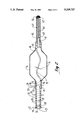
- FIG. 1 is a perspective view of the angioplasty catheter device inserted into a human blood vessel
- FIG. 2 is a cross-sectional view of the angioplasty catheter device with an inflated balloon as seen along the line 2--2 in FIG. 1;
- FIG. 3A is a cross-sectional view of an inflated balloon of the angioplasty catheter device of the present invention as seen along the line 3--3 of FIG. 1;
- FIG. 3B is a cross-sectional view of the balloon of the angioplasty catheter device as seen along the line 3--3 in FIG. 1, when the balloon is deflated.
- an angioplasty catheter device is attached to a fluid source 12 and inserted into a blood vessel 14 (shown in phantom) in preparation for an angioplasty procedure.
- Fluid source 12 provides fluid for expanding balloon 16 by infusion of fluid through hollow guide wire 18.
- any pumping device may be used which is suitable for pumping fluid from source 12 into guide wire 18.
- a hand-held syringe pump 19 may be used for this purpose.
- hollow guide wire 18 includes a tube 20 through which fluid from source 12 may be pumped to and from balloon 16. As shown in FIG. 2, the balloon 16 is in its inflated state. It is to be appreciated that, when balloon 16 is deflated (as shown in FIG. 3B), the outer diameter 30 of tube 18 is small enough to permit insertion of angioplasty catheter device 10 into the blood vessel 14. At the same time, inner diameter 24 of tube 20 is large enough to facilitate relatively rapid expansion and deflation of balloon 16.
- inner diameter 24 is preferably about fourteen thousandths (0.014) of an inch thick and tube wall 26 is approximately one thousandth (0.001) of an inch thick, resulting in an outer diameter 22 for tube 20 of approximately sixteen thousandths (0.016) of an inch.
- tube wall 26 is composed of a high strength, yet flexible, material such as stainless steel.
- the material of tube wall 26 should be non-oxidizing and non-toxic, in order to be compatible with both the fluid from source 12 and with the body materials contacted by angioplasty catheter device 10.
- a helical strengthening member 28 is shown bonded to tube wall 26.
- the geometry of member 28 may be any geometry suitable for providing structural support for tube wall 26, such as a ribbon.
- member 28 may be a single member 28 lead or a plurality of member 28 leads.
- member 28 should comprise a material which, when helically bonded in tension to the tube wall 26, provides sufficient hoop stress to structurally strengthen tube wall 26.
- the material of member 28 must be compatible with the material of tube wall 26 to provide for effective bonding.
- helical structural member 28 is composed of tungsten, but it is to be understood that other materials may be used which fulfill the strength and bonding requirements discussed above, such as molybdenum, stainless steel, or nickel.
- member 28 is bonded to tube wall 26 by nickel or other suitable electroplating.
- helical structural member 28 is two thousandths (0.002) of an inch thick.
- outside diameter 30 of hollow guide wire 18 is the sum of outer tube wall diameter 22, plus twice the thickness of helical structural member 28. This makes the overall outside diameter for device 10 approximately twenty thousandths (0.020) of an inch.
- the angular pitch 32 between successive coils of helical structural member 28, shown in FIG. 2 by dashed lines, should be selected to provide for both balloon 16 steerability, as well as for sufficient torque transmission through guide wire 18 to permit inserting balloon 16 into curved blood vessels.
- the present invention envisions a pitch 32 along the length of guide wire 18 which can be varied between twenty (20) and sixty (60) degrees, as steerability and torque transmission requirements dictate.
- pitch 32 may be relatively high (about forty-five (45) degrees) at the proximal end 34 of guide wire 18 for maximum torque transmission.
- Pitch 32 may then be gradually or suddenly reduced to thirty (30) degrees at the distal end 36 of guide wire 18, to provide for more flexibility and hence greater steerability of balloon 16.
- tube 20 is connected in fluid communication with a hollow flexible polymeric tube portion 37.
- Tube 20 and polymeric tube portion 37 may be attached to each other by any suitable means, such as by epoxy bonding.
- Polymeric tube portion 37 may be made of any suitable flexible material, such as polyimid, or may be a combination of a polyetherimid layer covered by a polyimid coating.
- a polymeric covering 39 is shown which surrounds and covers both tube 20 and polymeric tube portion 37.
- composite tube portion 37 is in turn connected in fluid communication with end 38 of balloon 16 by bonding tube portion 37 to end 38 in any suitable manner well known in the art.
- end 41 of helical structural member 28 is embedded in tube portion 37 to strengthen portion 37.
- balloon 16 is a hollow inflatable tube which may be made of any standard balloon material, such as polyethylene terephthalate or polyetherimid.
- FIG. 2 shows that a spring member 44 is disposed within balloon 16.
- Spring member 44 is attached in compression by any suitable manner well known in the art, e.g. electroplating, at its ends 46 and 48 to guide wire 18 and extension 40, respectively. More specifically, end 46 of spring member 44 is embedded within polymeric tube portion 37 and electroplated to end 45 of tube 20.
- FIG. 3A shows balloon 16 in its inflated state, with internal spring member 44 relatively compressed.
- the cross section of the balloon 16 shown in FIG. 3B has a comparatively narrow, pleated geometry when balloon 16 is deflated.
- spring member 44 is still somewhat in a state of compression. It will therefore be appreciated that because spring member 44 is in constant compression, spring member 44 tends to force guide wire 18 and guide wire extension 40 away from each other. This expansion tendency of spring member 44 in turn causes balloon 16, which is attached to both guide wire 18 and extension 40, to fold in pleats around spring 44 when balloon 16 is deflated, as shown in FIG.
- spring member 44 is constructed to transfer any torque that is applied at spring end 46 through spring member 44 to spring end 48.
- spring member 44 is a stainless steel ribbon-like structure with a width 56 of approximately six thousandths (0.006) of an inch.
- spring member 44 transfers torque applied to guide wire 18 to extension 40, thereby facilitating the steerability of balloon 16 and substantially preventing windup, or twisting, of balloon 16 when balloon 16 is either inflated or deflated.
- a hydrophilic porous plug 47 approximately five one thousandths (0.005) of an inch in diameter is positioned substantially coaxially with balloon 16 within end 42 of balloon 16. Plug 47 extends from balloon 16 into guide extension 40. Plug 47 facilitates filling device 10 and balloon 16 with fluid to purge device 10 of air prior to operational use.
- plug 47 may be made of any suitable material, such as porous polyethylene or porous teflon.
- the pores of plug 47 are large enough to permit the passage of air through plug 47 and out of extension 40 until substantially all of plug 47 has been wetted.
- the pores of plug 47 have diameters between approximately four millionths of an inch and twenty millionths of an inch. (0.000004-0.00002 inches). When substantially all of plug 47 has been wetted, substantially no fluid (air or liquid) can pass through plug 47.
- Extension 40 is attached to balloon 16 and spring member 44.
- Extension 40 includes a radiopaque flexible member 60, which is composed of a suitable material, such as gold or tungsten.
- the pitch 66 between successive coils of radiopaque flexible member 60 may be varied according to the steerability and pushability considerations discussed above.
- Extension 40 also has a steerable tip 62 integrally attached to a thin tape 64, which provide structural support to extension 40.
- the steerability of device 10 is provided for by tape 64 which may be bent at an angle suitable for the particular application of angioplasty device 10. As is well known to the skilled artisan, the bendability of tape 64 facilitates guiding device 10 through blood vessel 14. In the embodiment shown in FIG.
- tape 64 is a one to three thousandths (0.001-0.003) inch wide ribbon, and, like tip 62, is composed of tungsten, although any material which fulfills the structural and chemical compatibility criteria disclosed previously may be used.
- a suitable epoxy bonding material 68 is used to fill any voids within the structure of flexible member 60, and to bond member 60 to tape 64.
- the angioplasty catheter device 10 is attached to fluid source 12, for infusing fluid into hollow guide wire 18 as more fully disclosed below.
- balloon 16 is initially deflated, as shown in FIG. 3B, in preparation for the insertion procedure described below for angioplasty catheter device 10.
- fluid from source 12 Prior to insertion of device 10 into vessel 14, fluid from source 12 is pumped into device 10 to purge air from device 10.
- air is forced out of device 10 through the hydrophilic plug 47 disposed in end 42 of balloon 16.
- Guide wire extension 40 may then be bent as appropriate for the particular application of angioplasty catheter device 10 to provide for effective guiding of balloon 16.
- Guide wire extension 40 is next inserted into blood vessel 14.
- a short guide catheter (not shown) to establish access to the artery and then inserting catheter 10 through the short guide catheter.
- Balloon 16, in combination with hollow guide wire 18, is then inserted into blood vessel 14, until balloon 16 has been positioned at the desired location within the lumen of blood vessel 14.
- the hoop stress provided by helical structural member 28 enables guide wire 18 to withstand a relatively large amount of bending as it is inserted into blood vessel 14 before guide wire 18 undergoes plastic deformation.
- the hoop stress provided by helical structural member 28 makes guide wire 18 less prone to collapsing and buckling during the insertion process.
- balloon 16 Once balloon 16 has been positioned at the desired location within the lumen of vessel 14, fluid from source 12 is infused through hollow guide wire 18 into balloon 16. This expands balloon 16 to the approximate shape shown in FIG. 2 and further compresses spring member 44. After the lumen of blood vessel 14 has been thereby dilated, fluid within balloon 16 is drained back through hollow guide wire 18 to deflate balloon 16. As fluid is being drained from balloon 16, compressed spring member 44 tends to expand, causing balloon 16 to deflate around spring member 44 in the pleat-like folded shape shown in FIG. 3B. Angioplasty catheter device 10 is then withdrawn from blood vessel 14.
Landscapes
- Health & Medical Sciences (AREA)
- Life Sciences & Earth Sciences (AREA)
- Biophysics (AREA)
- Pulmonology (AREA)
- Engineering & Computer Science (AREA)
- Anesthesiology (AREA)
- Biomedical Technology (AREA)
- Heart & Thoracic Surgery (AREA)
- Hematology (AREA)
- Animal Behavior & Ethology (AREA)
- General Health & Medical Sciences (AREA)
- Public Health (AREA)
- Veterinary Medicine (AREA)
- Media Introduction/Drainage Providing Device (AREA)
Abstract
Description
Claims (24)
Priority Applications (1)
| Application Number | Priority Date | Filing Date | Title |
|---|---|---|---|
| US07/827,330 US5209727A (en) | 1992-01-29 | 1992-01-29 | Guide wire with integral angioplasty balloon |
Applications Claiming Priority (1)
| Application Number | Priority Date | Filing Date | Title |
|---|---|---|---|
| US07/827,330 US5209727A (en) | 1992-01-29 | 1992-01-29 | Guide wire with integral angioplasty balloon |
Publications (1)
| Publication Number | Publication Date |
|---|---|
| US5209727A true US5209727A (en) | 1993-05-11 |
Family
ID=25248936
Family Applications (1)
| Application Number | Title | Priority Date | Filing Date |
|---|---|---|---|
| US07/827,330 Expired - Fee Related US5209727A (en) | 1992-01-29 | 1992-01-29 | Guide wire with integral angioplasty balloon |
Country Status (1)
| Country | Link |
|---|---|
| US (1) | US5209727A (en) |
Cited By (93)
| Publication number | Priority date | Publication date | Assignee | Title |
|---|---|---|---|---|
| US5429597A (en) * | 1994-03-01 | 1995-07-04 | Boston Scientific Corporation | Kink resistant balloon catheter and method for use |
| US5505699A (en) * | 1994-03-24 | 1996-04-09 | Schneider (Usa) Inc. | Angioplasty device |
| US5522834A (en) * | 1992-10-15 | 1996-06-04 | Applied Medical Resources Corporation | Internal mammary artery catheter and method |
| EP0724891A1 (en) * | 1995-01-31 | 1996-08-07 | Cordis Europa N.V. | Ballooncatheter with stiff, elastically deformable basic body |
| US5545136A (en) * | 1993-09-14 | 1996-08-13 | Berger; J. Lee | Grooved catheter director apparatus |
| US5554114A (en) * | 1994-10-20 | 1996-09-10 | Micro Therapeutics, Inc. | Infusion device with preformed shape |
| US5562619A (en) * | 1993-08-19 | 1996-10-08 | Boston Scientific Corporation | Deflectable catheter |
| US5601538A (en) * | 1995-03-07 | 1997-02-11 | Medtronic, Inc. | Flow directed catheter with hydrophilic distal end |
| USRE35523E (en) * | 1991-10-11 | 1997-06-03 | Berger; J. Lee | Percutaneous carpal tunnel plasty method |
| US5817057A (en) * | 1996-09-13 | 1998-10-06 | Micro Interventional Systems, Inc. | Fluid propulsion steerable catheter and method |
| WO1999039649A1 (en) | 1998-02-10 | 1999-08-12 | Dubrul William R | Occlusion, anchoring, tensioning and flow direction apparatus and methods for use |
| US6059767A (en) * | 1998-02-25 | 2000-05-09 | Norborn Medical, Inc. | Steerable unitary infusion catheter/guide wire incorporating detachable infusion port assembly |
| US6068623A (en) * | 1997-03-06 | 2000-05-30 | Percusurge, Inc. | Hollow medical wires and methods of constructing same |
| US6544217B1 (en) * | 1999-02-01 | 2003-04-08 | Micro Therapeutics, Inc. | Guidewire-occluded balloon catheter |
| US20030088194A1 (en) * | 2001-11-06 | 2003-05-08 | Bonnette Michael J. | Gas Inflation/evacution system for guidewire having occlusive device |
| US20030097172A1 (en) * | 2000-03-27 | 2003-05-22 | Ilan Shalev | Narrowing implant |
| US20030114869A1 (en) * | 1996-07-26 | 2003-06-19 | Kensey Nash Corporation | Intravascular system for occluded blood vessels and guidewire for use therein |
| US6689151B2 (en) * | 2001-01-25 | 2004-02-10 | Scimed Life Systems, Inc. | Variable wall thickness for delivery sheath housing |
| US20040097995A1 (en) * | 1996-07-26 | 2004-05-20 | Nash John E. | System and method of use for agent delivery and revascularizing of grafts and vessels |
| US6746422B1 (en) | 2000-08-23 | 2004-06-08 | Norborn Medical, Inc. | Steerable support system with external ribs/slots that taper |
| US20040116916A1 (en) * | 2002-12-11 | 2004-06-17 | Lentz David J. | Coaxial catheter system for performing a single step cryoablation |
| US20040116917A1 (en) * | 2002-12-11 | 2004-06-17 | Lentz David J. | System and method for performing a single step cryoablation |
| US20040143287A1 (en) * | 2003-01-21 | 2004-07-22 | Angioscore, Inc. | Apparatus and methods for treating hardened vascular lesions |
| US20040210239A1 (en) * | 1996-07-26 | 2004-10-21 | Nash John E. | System and method of use for treating occluded vessels and diseased tissue |
| US6824543B2 (en) | 2002-12-11 | 2004-11-30 | Cryocor, Inc. | Guidance system for a cryocatheter |
| US20040265796A1 (en) * | 2003-04-17 | 2004-12-30 | Thomas Briese | Methods and kits for detecting SARS-associated coronavirus |
| US20050021071A1 (en) * | 2003-01-21 | 2005-01-27 | Angioscore, Inc. | Apparatus and methods for treating hardened vascular lesions |
| US20050021070A1 (en) * | 2003-01-21 | 2005-01-27 | Angioscore, Inc. | Methods and apparatus for manipulating vascular prostheses |
| US20050055082A1 (en) * | 2001-10-04 | 2005-03-10 | Shmuel Ben Muvhar | Flow reducing implant |
| US20050055077A1 (en) * | 2003-09-05 | 2005-03-10 | Doron Marco | Very low profile medical device system having an adjustable balloon |
| US20050113853A1 (en) * | 2000-04-06 | 2005-05-26 | Norborn Medical, Inc. | Guidewire for crossing occlusions or stenoses |
| US20050119615A1 (en) * | 2000-04-06 | 2005-06-02 | Norborn Medical, Inc. | Guidewire for crossing occlusions or stenoses |
| US20050177130A1 (en) * | 2004-02-10 | 2005-08-11 | Angioscore, Inc. | Balloon catheter with spiral folds |
| US20050182437A1 (en) * | 2001-11-06 | 2005-08-18 | Bonnette Michael J. | Guidewire assembly including a repeatably inflatable occlusive balloon on a guidewire ensheathed with a spiral coil |
| US6932828B2 (en) | 2001-11-06 | 2005-08-23 | Possis Medical, Inc. | Guidewire occlusion system utilizing repeatably inflatable gas-filled occlusive device |
| US20050209674A1 (en) * | 2003-09-05 | 2005-09-22 | Kutscher Tuvia D | Balloon assembly (V) |
| US20050228413A1 (en) * | 2004-04-12 | 2005-10-13 | Binmoeller Kenneth F | Automated transluminal tissue targeting and anchoring devices and methods |
| US20060074442A1 (en) * | 2000-04-06 | 2006-04-06 | Revascular Therapeutics, Inc. | Guidewire for crossing occlusions or stenoses |
| US20060106449A1 (en) * | 2002-08-08 | 2006-05-18 | Neovasc Medical Ltd. | Flow reducing implant |
| US20060106450A1 (en) * | 2002-08-08 | 2006-05-18 | Neovasc Medical Ltd. | Geometric flow regulator |
| US20060259005A1 (en) * | 2005-05-11 | 2006-11-16 | Angioscore, Inc. | Methods and systems for delivering substances into luminal walls |
| US20060282087A1 (en) * | 2005-06-09 | 2006-12-14 | Binmoeller Kenneth F | Methods and devices for endosonography-guided fundopexy |
| US7169161B2 (en) | 2001-11-06 | 2007-01-30 | Possis Medical, Inc. | Guidewire having occlusive device and repeatably crimpable proximal end |
| US7195625B2 (en) | 2002-12-11 | 2007-03-27 | Cryocor, Inc. | Catheter system for performing a single step cryoablation |
| US20070135825A1 (en) * | 2005-06-09 | 2007-06-14 | Binmoeller Kenneth F | Methods and devices for anchoring to tissue |
| US20070225615A1 (en) * | 2006-03-22 | 2007-09-27 | Revascular Therapeutics Inc. | Guidewire controller system |
| US20080097500A1 (en) * | 1996-07-26 | 2008-04-24 | Kensey Nash Corporation | System for opening a lumen in an occluded blood vessel |
| US7381198B2 (en) | 2000-08-23 | 2008-06-03 | Revascular Therapeutics, Inc. | Steerable distal support system |
| US20080140101A1 (en) * | 2006-12-07 | 2008-06-12 | Revascular Therapeutic, Inc. | Apparatus for crossing occlusions or stenoses |
| EP1911484A3 (en) * | 2000-12-12 | 2008-06-18 | Datascope Investment Corp. | Intra-aortic balloon catheter having a fiberoptic sensor |
| US20080221601A1 (en) * | 1998-02-25 | 2008-09-11 | Revascular Therapeutics, Inc. | Guidewire for crossing occlusions or stenoses having a shapeable distal end |
| US20080243151A1 (en) * | 2004-04-12 | 2008-10-02 | Binmoeller Kenneth F | Luminal Structure Anchoring Devices and Methods |
| US20080312671A1 (en) * | 2007-06-12 | 2008-12-18 | Possis Medical, Inc. | Infusion flow guidewire system |
| WO2009009472A1 (en) * | 2007-07-09 | 2009-01-15 | Wilson-Cook Medical Inc. | Balloon folding control mechanism |
| US20090018500A1 (en) * | 2007-07-09 | 2009-01-15 | Wilson-Cook Medical Inc. | Balloon catheter with deflation mechanism |
| US20090030380A1 (en) * | 2004-12-08 | 2009-01-29 | Xlumena, Inc. | Method and Apparatus for Performing Needle Guided Interventions |
| US20090105687A1 (en) * | 2007-10-05 | 2009-04-23 | Angioscore, Inc. | Scoring catheter with drug delivery membrane |
| US20090143729A1 (en) * | 2005-09-01 | 2009-06-04 | Medrad, Inc. | Torqueable kink-resistant guidewire |
| US7615031B2 (en) | 2005-09-01 | 2009-11-10 | Medrad, Inc. | Gas inflation/evacuation system incorporating a multiple element valved guidewire assembly having an occlusive device |
| US20090281557A1 (en) * | 2008-05-12 | 2009-11-12 | Xlumena, Inc. | Tissue anchor for securing tissue layers |
| US20090281379A1 (en) * | 2008-05-12 | 2009-11-12 | Xlumena, Inc. | System and method for transluminal access |
| WO2010033785A1 (en) * | 2008-09-22 | 2010-03-25 | Boston Scientific Scimed, Inc. | Biasing a catheter balloon |
| US20100100087A1 (en) * | 2008-10-20 | 2010-04-22 | Boston Scientific Scimed, Inc. | Providing Cryotherapy With a Balloon Catheter Having a Non-Uniform Thermal Profile |
| US20100125276A1 (en) * | 2008-11-14 | 2010-05-20 | Revascular Therapeutics, Inc. | Method and system for reversibly controlled drilling of luminal occlusions |
| US20100130938A1 (en) * | 2008-11-26 | 2010-05-27 | Revascular Therapeutics, Inc. | Delivery and exchange catheter for storing guidewire |
| US20100268029A1 (en) * | 2009-04-21 | 2010-10-21 | Xlumena, Inc. | Methods and apparatus for advancing a device from one body lumen to another |
| US7833239B2 (en) | 1996-07-26 | 2010-11-16 | Kensey Nash Corporation | System and method of use for revascularizing stenotic bypass grafts and other blood vessels |
| US20110112622A1 (en) * | 2009-05-29 | 2011-05-12 | Xlumena, Inc. | Apparatus and method for deploying stent across adjacent tissue layers |
| US20110112625A1 (en) * | 2000-03-27 | 2011-05-12 | Neovasc Medical Ltd. | Varying diameter vascular implant and balloon |
| US20110137394A1 (en) * | 2009-05-29 | 2011-06-09 | Xlumena, Inc. | Methods and systems for penetrating adjacent tissue layers |
| US20130304107A1 (en) * | 2012-05-09 | 2013-11-14 | Accessclosure, Inc. | Method and devices for flow occlusion during device exchanges |
| US20140088560A1 (en) * | 2011-03-30 | 2014-03-27 | Cornell University | Intra-luminal access apparatus and methods of using the same |
| US9173977B2 (en) | 2010-04-19 | 2015-11-03 | Angioscore, Inc. | Coating formulations for scoring or cutting balloon catheters |
| US9186487B2 (en) | 1997-11-12 | 2015-11-17 | Genesis Technologies Llc | Medical device and method |
| US9238119B2 (en) | 2010-08-12 | 2016-01-19 | Boston Scientific Limited | Infusion flow system and fluid coupling |
| US9351756B2 (en) | 2010-09-21 | 2016-05-31 | Angioscore, Inc. | Method and system for treating valve stenosis |
| US9364259B2 (en) | 2009-04-21 | 2016-06-14 | Xlumena, Inc. | System and method for delivering expanding trocar through a sheath |
| US9375328B2 (en) | 2001-11-09 | 2016-06-28 | Angioscore, Inc. | Balloon catheter with non-deployable stent |
| US9381041B2 (en) | 2009-04-21 | 2016-07-05 | Xlumena, Inc. | Methods and devices for access across adjacent tissue layers |
| US9498604B2 (en) | 1997-11-12 | 2016-11-22 | Genesis Technologies Llc | Medical device and method |
| US9561094B2 (en) | 2010-07-23 | 2017-02-07 | Nfinium Vascular Technologies, Llc | Devices and methods for treating venous diseases |
| US10086178B2 (en) | 2001-11-09 | 2018-10-02 | Angioscore, Inc. | Balloon catheter with non-deployable stent |
| US10117668B2 (en) | 2013-10-08 | 2018-11-06 | The Spectranetics Corporation | Balloon catheter with non-deployable stent having improved stability |
| US10434292B2 (en) | 2011-06-24 | 2019-10-08 | Access Closure | Method and devices for flow occlusion during device exchanges |
| US10463232B2 (en) | 2010-10-18 | 2019-11-05 | Sanovas Intellectual Property, Llc | Anchored guidewire |
| US10952732B2 (en) | 2013-02-21 | 2021-03-23 | Boston Scientific Scimed Inc. | Devices and methods for forming an anastomosis |
| US11266414B2 (en) | 2014-06-04 | 2022-03-08 | Vascular Development Corp, Llc | Low radial force vascular device and method of occlusion |
| CN115813626A (en) * | 2022-10-18 | 2023-03-21 | 上海心玮医疗科技股份有限公司 | Blood flow guider's transport seal wire |
| US11723783B2 (en) | 2019-01-23 | 2023-08-15 | Neovasc Medical Ltd. | Covered flow modifying apparatus |
| US12295581B2 (en) | 2017-11-22 | 2025-05-13 | Front Line Medical Technologies Inc. | Devices and method for blood vessel occlusion |
| US12303105B2 (en) | 2004-04-12 | 2025-05-20 | Boston Scientific Scimed, Inc. | Luminal structure anchoring devices and methods |
| US12440650B2 (en) | 2010-05-19 | 2025-10-14 | Vascular Development Corp, Llc | Augmented delivery catheter and method |
| US12475994B2 (en) | 2021-06-18 | 2025-11-18 | Front Line Medical Technologies Inc. | Devices and method for blood vessel occlusion |
Citations (19)
| Publication number | Priority date | Publication date | Assignee | Title |
|---|---|---|---|---|
| US4140126A (en) * | 1977-02-18 | 1979-02-20 | Choudhury M Hasan | Method for performing aneurysm repair |
| US4141364A (en) * | 1977-03-18 | 1979-02-27 | Jorge Schultze | Expandable endotracheal or urethral tube |
| US4292974A (en) * | 1980-01-30 | 1981-10-06 | Thomas J. Fogarty | Dilatation catheter apparatus and method |
| US4406656A (en) * | 1981-06-01 | 1983-09-27 | Brack Gillium Hattler | Venous catheter having collapsible multi-lumens |
| US4608984A (en) * | 1980-10-17 | 1986-09-02 | Fogarty Thomas J | Self-retracting dilatation catheter |
| US4627436A (en) * | 1984-03-01 | 1986-12-09 | Innoventions Biomedical Inc. | Angioplasty catheter and method for use thereof |
| US4685458A (en) * | 1984-03-01 | 1987-08-11 | Vaser, Inc. | Angioplasty catheter and method for use thereof |
| US4686982A (en) * | 1985-06-19 | 1987-08-18 | John Nash | Spiral wire bearing for rotating wire drive catheter |
| US4705517A (en) * | 1985-09-03 | 1987-11-10 | Becton, Dickinson And Company | Percutaneously deliverable intravascular occlusion prosthesis |
| US4787388A (en) * | 1985-11-29 | 1988-11-29 | Schneider - Shiley Ag | Method for opening constricted regions in the cardiovascular system |
| US4813934A (en) * | 1987-08-07 | 1989-03-21 | Target Therapeutics | Valved catheter device and method |
| US4838268A (en) * | 1988-03-07 | 1989-06-13 | Scimed Life Systems, Inc. | Non-over-the wire balloon catheter |
| US4875481A (en) * | 1988-07-01 | 1989-10-24 | Cordis Corporation | Catheter with coiled wire attachment |
| US4896669A (en) * | 1988-08-31 | 1990-01-30 | Meadox Medicals, Inc. | Dilatation catheter |
| US4917088A (en) * | 1985-05-02 | 1990-04-17 | C. R. Bard, Inc. | Balloon dilation probe |
| US4946466A (en) * | 1989-03-03 | 1990-08-07 | Cordis Corporation | Transluminal angioplasty apparatus |
| US5002559A (en) * | 1989-11-30 | 1991-03-26 | Numed | PTCA catheter |
| US5042985A (en) * | 1989-05-11 | 1991-08-27 | Advanced Cardiovascular Systems, Inc. | Dilatation catheter suitable for peripheral arteries |
| US5102390A (en) * | 1985-05-02 | 1992-04-07 | C. R. Bard, Inc. | Microdilatation probe and system for performing angioplasty in highly stenosed blood vessels |
-
1992
- 1992-01-29 US US07/827,330 patent/US5209727A/en not_active Expired - Fee Related
Patent Citations (20)
| Publication number | Priority date | Publication date | Assignee | Title |
|---|---|---|---|---|
| US4140126A (en) * | 1977-02-18 | 1979-02-20 | Choudhury M Hasan | Method for performing aneurysm repair |
| US4141364A (en) * | 1977-03-18 | 1979-02-27 | Jorge Schultze | Expandable endotracheal or urethral tube |
| US4292974A (en) * | 1980-01-30 | 1981-10-06 | Thomas J. Fogarty | Dilatation catheter apparatus and method |
| US4608984A (en) * | 1980-10-17 | 1986-09-02 | Fogarty Thomas J | Self-retracting dilatation catheter |
| US4406656A (en) * | 1981-06-01 | 1983-09-27 | Brack Gillium Hattler | Venous catheter having collapsible multi-lumens |
| US4627436A (en) * | 1984-03-01 | 1986-12-09 | Innoventions Biomedical Inc. | Angioplasty catheter and method for use thereof |
| US4685458A (en) * | 1984-03-01 | 1987-08-11 | Vaser, Inc. | Angioplasty catheter and method for use thereof |
| US4917088A (en) * | 1985-05-02 | 1990-04-17 | C. R. Bard, Inc. | Balloon dilation probe |
| US5102390A (en) * | 1985-05-02 | 1992-04-07 | C. R. Bard, Inc. | Microdilatation probe and system for performing angioplasty in highly stenosed blood vessels |
| US4686982A (en) * | 1985-06-19 | 1987-08-18 | John Nash | Spiral wire bearing for rotating wire drive catheter |
| US4705517A (en) * | 1985-09-03 | 1987-11-10 | Becton, Dickinson And Company | Percutaneously deliverable intravascular occlusion prosthesis |
| US4787388A (en) * | 1985-11-29 | 1988-11-29 | Schneider - Shiley Ag | Method for opening constricted regions in the cardiovascular system |
| US4813934A (en) * | 1987-08-07 | 1989-03-21 | Target Therapeutics | Valved catheter device and method |
| US4813934B1 (en) * | 1987-08-07 | 1992-05-12 | Target Therapeutics Inc | |
| US4838268A (en) * | 1988-03-07 | 1989-06-13 | Scimed Life Systems, Inc. | Non-over-the wire balloon catheter |
| US4875481A (en) * | 1988-07-01 | 1989-10-24 | Cordis Corporation | Catheter with coiled wire attachment |
| US4896669A (en) * | 1988-08-31 | 1990-01-30 | Meadox Medicals, Inc. | Dilatation catheter |
| US4946466A (en) * | 1989-03-03 | 1990-08-07 | Cordis Corporation | Transluminal angioplasty apparatus |
| US5042985A (en) * | 1989-05-11 | 1991-08-27 | Advanced Cardiovascular Systems, Inc. | Dilatation catheter suitable for peripheral arteries |
| US5002559A (en) * | 1989-11-30 | 1991-03-26 | Numed | PTCA catheter |
Cited By (178)
| Publication number | Priority date | Publication date | Assignee | Title |
|---|---|---|---|---|
| USRE35523E (en) * | 1991-10-11 | 1997-06-03 | Berger; J. Lee | Percutaneous carpal tunnel plasty method |
| US5522834A (en) * | 1992-10-15 | 1996-06-04 | Applied Medical Resources Corporation | Internal mammary artery catheter and method |
| US5865800A (en) * | 1993-08-19 | 1999-02-02 | Boston Scientific Corporation | Deflectable catheter |
| US5562619A (en) * | 1993-08-19 | 1996-10-08 | Boston Scientific Corporation | Deflectable catheter |
| US5545136A (en) * | 1993-09-14 | 1996-08-13 | Berger; J. Lee | Grooved catheter director apparatus |
| WO1995023626A1 (en) * | 1994-03-01 | 1995-09-08 | Boston Scientific Corporation | Removable core balloon on a wire |
| US5429597A (en) * | 1994-03-01 | 1995-07-04 | Boston Scientific Corporation | Kink resistant balloon catheter and method for use |
| US5505699A (en) * | 1994-03-24 | 1996-04-09 | Schneider (Usa) Inc. | Angioplasty device |
| US5554114A (en) * | 1994-10-20 | 1996-09-10 | Micro Therapeutics, Inc. | Infusion device with preformed shape |
| NL9500173A (en) * | 1995-01-31 | 1996-09-02 | Cordis Europ | Balloon catheter with rigid, elastically deformable base body. |
| EP0724891A1 (en) * | 1995-01-31 | 1996-08-07 | Cordis Europa N.V. | Ballooncatheter with stiff, elastically deformable basic body |
| US5820613A (en) * | 1995-01-31 | 1998-10-13 | Cordis Corporation | Balloon catheter with reinforced and elastically deformable basic body |
| US5601538A (en) * | 1995-03-07 | 1997-02-11 | Medtronic, Inc. | Flow directed catheter with hydrophilic distal end |
| US7833239B2 (en) | 1996-07-26 | 2010-11-16 | Kensey Nash Corporation | System and method of use for revascularizing stenotic bypass grafts and other blood vessels |
| US6652546B1 (en) * | 1996-07-26 | 2003-11-25 | Kensey Nash Corporation | System and method of use for revascularizing stenotic bypass grafts and other occluded blood vessels |
| US20080097500A1 (en) * | 1996-07-26 | 2008-04-24 | Kensey Nash Corporation | System for opening a lumen in an occluded blood vessel |
| US20090292276A1 (en) * | 1996-07-26 | 2009-11-26 | Nash John E | System and method of use for agent delivery and revascularizing of grafts and vessels |
| US20040097995A1 (en) * | 1996-07-26 | 2004-05-20 | Nash John E. | System and method of use for agent delivery and revascularizing of grafts and vessels |
| US6936056B2 (en) | 1996-07-26 | 2005-08-30 | Kensey Nash Corporation | Intravascular system for occluded blood vessels and guidewire for use therein |
| US20040210239A1 (en) * | 1996-07-26 | 2004-10-21 | Nash John E. | System and method of use for treating occluded vessels and diseased tissue |
| US7981129B2 (en) | 1996-07-26 | 2011-07-19 | Kensey Nash Corporation | System for opening a lumen in an occluded blood vessel |
| US8226673B2 (en) | 1996-07-26 | 2012-07-24 | Kensey Nash Corporation | System and method of use for agent delivery and revascularizing of grafts and vessels |
| US20030114869A1 (en) * | 1996-07-26 | 2003-06-19 | Kensey Nash Corporation | Intravascular system for occluded blood vessels and guidewire for use therein |
| US7534249B2 (en) | 1996-07-26 | 2009-05-19 | Kensey Nash Corporation | System and method of use for agent delivery and revascularizing of grafts and vessels |
| US5817057A (en) * | 1996-09-13 | 1998-10-06 | Micro Interventional Systems, Inc. | Fluid propulsion steerable catheter and method |
| US6375628B1 (en) | 1997-03-06 | 2002-04-23 | Medtronic Percusurge, Inc. | Hollow medical wires and methods of constructing same |
| US6217567B1 (en) | 1997-03-06 | 2001-04-17 | Percusurge, Inc. | Hollow medical wires and methods of constructing same |
| US6068623A (en) * | 1997-03-06 | 2000-05-30 | Percusurge, Inc. | Hollow medical wires and methods of constructing same |
| US9186487B2 (en) | 1997-11-12 | 2015-11-17 | Genesis Technologies Llc | Medical device and method |
| US9498604B2 (en) | 1997-11-12 | 2016-11-22 | Genesis Technologies Llc | Medical device and method |
| WO1999039649A1 (en) | 1998-02-10 | 1999-08-12 | Dubrul William R | Occlusion, anchoring, tensioning and flow direction apparatus and methods for use |
| US9254143B2 (en) | 1998-02-25 | 2016-02-09 | Revascular Therapeutics, Inc. | Guidewire for crossing occlusions or stenoses having a shapeable distal end |
| US20080221601A1 (en) * | 1998-02-25 | 2008-09-11 | Revascular Therapeutics, Inc. | Guidewire for crossing occlusions or stenoses having a shapeable distal end |
| US6059767A (en) * | 1998-02-25 | 2000-05-09 | Norborn Medical, Inc. | Steerable unitary infusion catheter/guide wire incorporating detachable infusion port assembly |
| US6544217B1 (en) * | 1999-02-01 | 2003-04-08 | Micro Therapeutics, Inc. | Guidewire-occluded balloon catheter |
| US8858612B2 (en) | 2000-03-27 | 2014-10-14 | Neovasc Medical Inc. | Methods for treating abnormal growths in the body using a flow reducing implant |
| US9364354B2 (en) | 2000-03-27 | 2016-06-14 | Neovasc Medical Ltd | Methods for treating abnormal growths in the body using a flow reducing implant |
| US20030097172A1 (en) * | 2000-03-27 | 2003-05-22 | Ilan Shalev | Narrowing implant |
| US20110112625A1 (en) * | 2000-03-27 | 2011-05-12 | Neovasc Medical Ltd. | Varying diameter vascular implant and balloon |
| US11497503B2 (en) | 2000-03-27 | 2022-11-15 | Neovasc Medical Ltd. | Methods for treating abnormal growths in the body using a flow reducing implant |
| US20100114299A1 (en) * | 2000-03-27 | 2010-05-06 | Neovasc Medical Ltd. | Flow reducing implant |
| US8556954B2 (en) | 2000-03-27 | 2013-10-15 | Neovasc Medical Ltd | Methods for treating abnormal growths in the body using a flow reducing implant |
| US10542994B2 (en) | 2000-03-27 | 2020-01-28 | Neovasc Medical Ltd. | Methods for treating abnormal growths in the body using a flow reducing implant |
| US8496680B2 (en) | 2000-04-06 | 2013-07-30 | Revascular Therapeutics Inc. | Guidewire for crossing occlusions or stenoses |
| US8353922B2 (en) | 2000-04-06 | 2013-01-15 | Revascular Therapeutics, Inc | Guidewire for crossing occlusions or stenoses |
| US20050113853A1 (en) * | 2000-04-06 | 2005-05-26 | Norborn Medical, Inc. | Guidewire for crossing occlusions or stenoses |
| US8043312B2 (en) | 2000-04-06 | 2011-10-25 | Revascular Therapeutics Inc. | Guidewire for crossing occlusions or stenoses |
| US9113955B2 (en) | 2000-04-06 | 2015-08-25 | Revascular Therapeutics, Inc. | Guidewire for crossing occlusions or stenoses |
| US8043314B2 (en) | 2000-04-06 | 2011-10-25 | Revascular Therapeutics Inc. | Guidewire for crossing occlusions or stenoses |
| US20050119615A1 (en) * | 2000-04-06 | 2005-06-02 | Norborn Medical, Inc. | Guidewire for crossing occlusions or stenoses |
| US20050228418A1 (en) * | 2000-04-06 | 2005-10-13 | Revascular Therapeutics Inc. | Guidewire for crossing occlusions or stenoses |
| US20060074442A1 (en) * | 2000-04-06 | 2006-04-06 | Revascular Therapeutics, Inc. | Guidewire for crossing occlusions or stenoses |
| US7628763B2 (en) | 2000-04-06 | 2009-12-08 | Revascular Therapeutics, Inc. | Guidewire for crossing occlusions or stenoses |
| US20100049169A1 (en) * | 2000-04-06 | 2010-02-25 | Revascular Therapeutics, Inc. | Guidewire for crossing occlusions or stenoses |
| US8747332B2 (en) | 2000-04-06 | 2014-06-10 | Revascular Therapeutics Inc. | Guidewire for crossing occlusions or stenoses |
| US6746422B1 (en) | 2000-08-23 | 2004-06-08 | Norborn Medical, Inc. | Steerable support system with external ribs/slots that taper |
| US7381198B2 (en) | 2000-08-23 | 2008-06-03 | Revascular Therapeutics, Inc. | Steerable distal support system |
| EP1911484A3 (en) * | 2000-12-12 | 2008-06-18 | Datascope Investment Corp. | Intra-aortic balloon catheter having a fiberoptic sensor |
| US6689151B2 (en) * | 2001-01-25 | 2004-02-10 | Scimed Life Systems, Inc. | Variable wall thickness for delivery sheath housing |
| US7097652B2 (en) | 2001-01-25 | 2006-08-29 | Scimed Life Systems, Inc. | Variable wall thickness for delivery sheath housing |
| US20040158278A1 (en) * | 2001-01-25 | 2004-08-12 | Scimed Life Systems, Inc. | Variable wall thickness for delivery sheath housing |
| US20050055082A1 (en) * | 2001-10-04 | 2005-03-10 | Shmuel Ben Muvhar | Flow reducing implant |
| US20050182437A1 (en) * | 2001-11-06 | 2005-08-18 | Bonnette Michael J. | Guidewire assembly including a repeatably inflatable occlusive balloon on a guidewire ensheathed with a spiral coil |
| US7169161B2 (en) | 2001-11-06 | 2007-01-30 | Possis Medical, Inc. | Guidewire having occlusive device and repeatably crimpable proximal end |
| US20030088194A1 (en) * | 2001-11-06 | 2003-05-08 | Bonnette Michael J. | Gas Inflation/evacution system for guidewire having occlusive device |
| US6942678B2 (en) | 2001-11-06 | 2005-09-13 | Possis Medical, Inc. | Gas inflation/evacuation system and sealing system for guidewire assembly having occlusive device |
| US6932828B2 (en) | 2001-11-06 | 2005-08-23 | Possis Medical, Inc. | Guidewire occlusion system utilizing repeatably inflatable gas-filled occlusive device |
| US10086178B2 (en) | 2001-11-09 | 2018-10-02 | Angioscore, Inc. | Balloon catheter with non-deployable stent |
| US9375328B2 (en) | 2001-11-09 | 2016-06-28 | Angioscore, Inc. | Balloon catheter with non-deployable stent |
| US11571554B2 (en) | 2001-11-09 | 2023-02-07 | Angioscore, Inc. | Balloon catheter with non-deployable stent |
| US20060106450A1 (en) * | 2002-08-08 | 2006-05-18 | Neovasc Medical Ltd. | Geometric flow regulator |
| US20060106449A1 (en) * | 2002-08-08 | 2006-05-18 | Neovasc Medical Ltd. | Flow reducing implant |
| US7195625B2 (en) | 2002-12-11 | 2007-03-27 | Cryocor, Inc. | Catheter system for performing a single step cryoablation |
| US20040116916A1 (en) * | 2002-12-11 | 2004-06-17 | Lentz David J. | Coaxial catheter system for performing a single step cryoablation |
| US6824543B2 (en) | 2002-12-11 | 2004-11-30 | Cryocor, Inc. | Guidance system for a cryocatheter |
| US6796979B2 (en) | 2002-12-11 | 2004-09-28 | Cryocor, Inc. | Coaxial catheter system for performing a single step cryoablation |
| US6893433B2 (en) | 2002-12-11 | 2005-05-17 | Cryocor, Inc. | System and method for performing a single step cryoablation |
| US20040116917A1 (en) * | 2002-12-11 | 2004-06-17 | Lentz David J. | System and method for performing a single step cryoablation |
| US20040143287A1 (en) * | 2003-01-21 | 2004-07-22 | Angioscore, Inc. | Apparatus and methods for treating hardened vascular lesions |
| US20040243158A1 (en) * | 2003-01-21 | 2004-12-02 | Angioscore, Inc., A Delaware Corporation | Apparatus and methods for treating hardened vascular lesions |
| US9962529B2 (en) | 2003-01-21 | 2018-05-08 | Angioscore, Inc. | Apparatus and methods for treating hardened vascular lesions |
| US20050021071A1 (en) * | 2003-01-21 | 2005-01-27 | Angioscore, Inc. | Apparatus and methods for treating hardened vascular lesions |
| US8454636B2 (en) | 2003-01-21 | 2013-06-04 | Angioscore, Inc. | Apparatus and methods for treating hardened vascular lesions |
| US7686824B2 (en) | 2003-01-21 | 2010-03-30 | Angioscore, Inc. | Apparatus and methods for treating hardened vascular lesions |
| US20050021070A1 (en) * | 2003-01-21 | 2005-01-27 | Angioscore, Inc. | Methods and apparatus for manipulating vascular prostheses |
| US7955350B2 (en) | 2003-01-21 | 2011-06-07 | Angioscore, Inc. | Apparatus and methods for treating hardened vascular lesions |
| US8080026B2 (en) | 2003-01-21 | 2011-12-20 | Angioscore, Inc. | Apparatus and methods for treating hardened vascular lesions |
| US8721667B2 (en) | 2003-01-21 | 2014-05-13 | Angioscore, Inc. | Apparatus and methods for treating hardened vascular lesions |
| US10722694B2 (en) | 2003-01-21 | 2020-07-28 | Angioscore, Inc. | Apparatus and methods for treating hardened vascular lesions |
| US20040265796A1 (en) * | 2003-04-17 | 2004-12-30 | Thomas Briese | Methods and kits for detecting SARS-associated coronavirus |
| US20050055077A1 (en) * | 2003-09-05 | 2005-03-10 | Doron Marco | Very low profile medical device system having an adjustable balloon |
| US20050209674A1 (en) * | 2003-09-05 | 2005-09-22 | Kutscher Tuvia D | Balloon assembly (V) |
| US20050177130A1 (en) * | 2004-02-10 | 2005-08-11 | Angioscore, Inc. | Balloon catheter with spiral folds |
| US11857160B2 (en) | 2004-04-12 | 2024-01-02 | Boston Scientific Scimed, Inc. | Luminal structure anchoring devices and methods |
| US12303105B2 (en) | 2004-04-12 | 2025-05-20 | Boston Scientific Scimed, Inc. | Luminal structure anchoring devices and methods |
| US10945735B2 (en) | 2004-04-12 | 2021-03-16 | Boston Scientific Scimed, Inc. | Luminal structure anchoring devices and methods |
| US20050228413A1 (en) * | 2004-04-12 | 2005-10-13 | Binmoeller Kenneth F | Automated transluminal tissue targeting and anchoring devices and methods |
| US8425539B2 (en) | 2004-04-12 | 2013-04-23 | Xlumena, Inc. | Luminal structure anchoring devices and methods |
| US20080243151A1 (en) * | 2004-04-12 | 2008-10-02 | Binmoeller Kenneth F | Luminal Structure Anchoring Devices and Methods |
| US8328837B2 (en) | 2004-12-08 | 2012-12-11 | Xlumena, Inc. | Method and apparatus for performing needle guided interventions |
| US8617196B2 (en) | 2004-12-08 | 2013-12-31 | Xlumena, Inc. | Method and apparatus for performing needle guided interventions |
| US20090030380A1 (en) * | 2004-12-08 | 2009-01-29 | Xlumena, Inc. | Method and Apparatus for Performing Needle Guided Interventions |
| US20060259005A1 (en) * | 2005-05-11 | 2006-11-16 | Angioscore, Inc. | Methods and systems for delivering substances into luminal walls |
| US10076641B2 (en) | 2005-05-11 | 2018-09-18 | The Spectranetics Corporation | Methods and systems for delivering substances into luminal walls |
| US9586031B2 (en) | 2005-05-11 | 2017-03-07 | Angioscore, Inc. | Methods and systems for delivering substances into luminal walls |
| US10342960B2 (en) | 2005-05-11 | 2019-07-09 | Angioscore, Inc. | Methods and systems for delivering substances into luminal walls |
| US8864743B2 (en) | 2005-05-11 | 2014-10-21 | Angioscore, Inc. | Methods and systems for delivering substances into luminal walls |
| US11420030B2 (en) | 2005-05-11 | 2022-08-23 | Angioscore, Inc. | Methods and systems for delivering substances into luminal walls |
| US8777967B2 (en) | 2005-06-09 | 2014-07-15 | Xlumena, Inc. | Methods and devices for anchoring to tissue |
| US20060282087A1 (en) * | 2005-06-09 | 2006-12-14 | Binmoeller Kenneth F | Methods and devices for endosonography-guided fundopexy |
| US20070135825A1 (en) * | 2005-06-09 | 2007-06-14 | Binmoeller Kenneth F | Methods and devices for anchoring to tissue |
| US8784437B2 (en) | 2005-06-09 | 2014-07-22 | Xlumena, Inc. | Methods and devices for endosonography-guided fundoplexy |
| US7615031B2 (en) | 2005-09-01 | 2009-11-10 | Medrad, Inc. | Gas inflation/evacuation system incorporating a multiple element valved guidewire assembly having an occlusive device |
| US20090143729A1 (en) * | 2005-09-01 | 2009-06-04 | Medrad, Inc. | Torqueable kink-resistant guidewire |
| US8157766B2 (en) | 2005-09-01 | 2012-04-17 | Medrad, Inc. | Torqueable kink-resistant guidewire |
| US9585686B2 (en) | 2005-09-28 | 2017-03-07 | Boston Scientific Limited | Infusion flow guidewire system |
| US20070225615A1 (en) * | 2006-03-22 | 2007-09-27 | Revascular Therapeutics Inc. | Guidewire controller system |
| US20080140101A1 (en) * | 2006-12-07 | 2008-06-12 | Revascular Therapeutic, Inc. | Apparatus for crossing occlusions or stenoses |
| US20080312671A1 (en) * | 2007-06-12 | 2008-12-18 | Possis Medical, Inc. | Infusion flow guidewire system |
| US8608703B2 (en) | 2007-06-12 | 2013-12-17 | Medrad, Inc. | Infusion flow guidewire system |
| US7976496B2 (en) * | 2007-07-09 | 2011-07-12 | Cook Medical Technologies Llc | Balloon folding control mechanism |
| US7972299B2 (en) * | 2007-07-09 | 2011-07-05 | Cook Medical Technologies Llc | Balloon catheter with deflation mechanism |
| US20090024087A1 (en) * | 2007-07-09 | 2009-01-22 | Wilson-Cook Medical Inc. | Balloon folding control mechanism |
| US20090018500A1 (en) * | 2007-07-09 | 2009-01-15 | Wilson-Cook Medical Inc. | Balloon catheter with deflation mechanism |
| WO2009009472A1 (en) * | 2007-07-09 | 2009-01-15 | Wilson-Cook Medical Inc. | Balloon folding control mechanism |
| US20090105687A1 (en) * | 2007-10-05 | 2009-04-23 | Angioscore, Inc. | Scoring catheter with drug delivery membrane |
| US8454632B2 (en) | 2008-05-12 | 2013-06-04 | Xlumena, Inc. | Tissue anchor for securing tissue layers |
| US20090281379A1 (en) * | 2008-05-12 | 2009-11-12 | Xlumena, Inc. | System and method for transluminal access |
| US20090281557A1 (en) * | 2008-05-12 | 2009-11-12 | Xlumena, Inc. | Tissue anchor for securing tissue layers |
| US12544072B2 (en) | 2008-05-12 | 2026-02-10 | Boston Scientific Scimed, Inc. | Tissue anchor for securing tissue layers |
| US10076330B2 (en) | 2008-05-12 | 2018-09-18 | Xlumena, Inc. | Tissue anchor for securing tissue layers |
| WO2010033785A1 (en) * | 2008-09-22 | 2010-03-25 | Boston Scientific Scimed, Inc. | Biasing a catheter balloon |
| JP2012502759A (en) * | 2008-09-22 | 2012-02-02 | ボストン サイエンティフィック サイムド,インコーポレイテッド | Energizing the catheter balloon |
| US20100076402A1 (en) * | 2008-09-22 | 2010-03-25 | James Mazzone | Biasing a Catheter Balloon |
| US8333757B2 (en) | 2008-09-22 | 2012-12-18 | Boston Scientific Scimed, Inc. | Biasing a catheter balloon |
| US20100100087A1 (en) * | 2008-10-20 | 2010-04-22 | Boston Scientific Scimed, Inc. | Providing Cryotherapy With a Balloon Catheter Having a Non-Uniform Thermal Profile |
| US8465481B2 (en) | 2008-10-20 | 2013-06-18 | Boston Scientific Scimed, Inc. | Providing cryotherapy with a balloon catheter having a non-uniform thermal profile |
| US20100125276A1 (en) * | 2008-11-14 | 2010-05-20 | Revascular Therapeutics, Inc. | Method and system for reversibly controlled drilling of luminal occlusions |
| US9820770B2 (en) | 2008-11-14 | 2017-11-21 | Boston Scientific Scimed, Inc. | Method and system for reversibly controlled drilling of luminal occlusions |
| US8657821B2 (en) | 2008-11-14 | 2014-02-25 | Revascular Therapeutics Inc. | Method and system for reversibly controlled drilling of luminal occlusions |
| US20100130938A1 (en) * | 2008-11-26 | 2010-05-27 | Revascular Therapeutics, Inc. | Delivery and exchange catheter for storing guidewire |
| US8801691B2 (en) | 2008-11-26 | 2014-08-12 | Revascular Therapeutics, Inc. | Delivery and exchange catheter for storing guidewire |
| US8162891B2 (en) | 2008-11-26 | 2012-04-24 | Revascular Therapeutics, Inc. | Delivery and exchange catheter for storing guidewire |
| US20100268029A1 (en) * | 2009-04-21 | 2010-10-21 | Xlumena, Inc. | Methods and apparatus for advancing a device from one body lumen to another |
| EP3085408A1 (en) | 2009-04-21 | 2016-10-26 | Xlumena, Inc. | Apparatus for advancing a device from one body lumen to another |
| US9381041B2 (en) | 2009-04-21 | 2016-07-05 | Xlumena, Inc. | Methods and devices for access across adjacent tissue layers |
| EP3730180A1 (en) | 2009-04-21 | 2020-10-28 | Boston Scientific Scimed Inc. | Apparatus for advancing a device from one body lumen to another |
| US9364259B2 (en) | 2009-04-21 | 2016-06-14 | Xlumena, Inc. | System and method for delivering expanding trocar through a sheath |
| US20110137394A1 (en) * | 2009-05-29 | 2011-06-09 | Xlumena, Inc. | Methods and systems for penetrating adjacent tissue layers |
| US8357193B2 (en) | 2009-05-29 | 2013-01-22 | Xlumena, Inc. | Apparatus and method for deploying stent across adjacent tissue layers |
| US12458356B2 (en) | 2009-05-29 | 2025-11-04 | Boston Scientific Scimed, Inc. | Apparatus and method for deploying stent across adjacent tissue layers |
| US9888926B2 (en) | 2009-05-29 | 2018-02-13 | Boston Scientific Scimed, Inc. | Apparatus and method for deploying stent across adjacent tissue layers |
| US20110112622A1 (en) * | 2009-05-29 | 2011-05-12 | Xlumena, Inc. | Apparatus and method for deploying stent across adjacent tissue layers |
| US10314947B2 (en) | 2010-04-19 | 2019-06-11 | Angioscore, Inc. | Coating formulations for scoring or cutting balloon catheters |
| US10471184B2 (en) | 2010-04-19 | 2019-11-12 | Angioscore, Inc. | Coating formulations for scoring or cutting balloon catheters |
| US9173977B2 (en) | 2010-04-19 | 2015-11-03 | Angioscore, Inc. | Coating formulations for scoring or cutting balloon catheters |
| US12440650B2 (en) | 2010-05-19 | 2025-10-14 | Vascular Development Corp, Llc | Augmented delivery catheter and method |
| US9561094B2 (en) | 2010-07-23 | 2017-02-07 | Nfinium Vascular Technologies, Llc | Devices and methods for treating venous diseases |
| US9238119B2 (en) | 2010-08-12 | 2016-01-19 | Boston Scientific Limited | Infusion flow system and fluid coupling |
| US9351756B2 (en) | 2010-09-21 | 2016-05-31 | Angioscore, Inc. | Method and system for treating valve stenosis |
| US9364254B2 (en) | 2010-09-21 | 2016-06-14 | Angioscore, Inc. | Method and system for treating valve stenosis |
| US10736652B2 (en) | 2010-09-21 | 2020-08-11 | Angioscore, Inc. | Method and system for treating valve stenosis |
| US10463232B2 (en) | 2010-10-18 | 2019-11-05 | Sanovas Intellectual Property, Llc | Anchored guidewire |
| US20140088560A1 (en) * | 2011-03-30 | 2014-03-27 | Cornell University | Intra-luminal access apparatus and methods of using the same |
| US10434292B2 (en) | 2011-06-24 | 2019-10-08 | Access Closure | Method and devices for flow occlusion during device exchanges |
| US20130304107A1 (en) * | 2012-05-09 | 2013-11-14 | Accessclosure, Inc. | Method and devices for flow occlusion during device exchanges |
| US9532785B2 (en) * | 2012-05-09 | 2017-01-03 | Access Closure, Inc. | Method and devices for flow occlusion during device exchanges |
| US12343072B2 (en) | 2012-05-17 | 2025-07-01 | Boston Scientific Scimed, Inc. | Methods and devices for access across adjacent tissue layers |
| US12201299B2 (en) | 2013-02-21 | 2025-01-21 | Boston Scientific Scimed, Inc. | Devices and methods for forming an anastomosis |
| US10952732B2 (en) | 2013-02-21 | 2021-03-23 | Boston Scientific Scimed Inc. | Devices and methods for forming an anastomosis |
| US10117668B2 (en) | 2013-10-08 | 2018-11-06 | The Spectranetics Corporation | Balloon catheter with non-deployable stent having improved stability |
| US10485571B2 (en) | 2013-10-08 | 2019-11-26 | Angioscore, Inc. | Balloon catheter with non-deployable stent having improved stability |
| US11266414B2 (en) | 2014-06-04 | 2022-03-08 | Vascular Development Corp, Llc | Low radial force vascular device and method of occlusion |
| US12357314B2 (en) | 2014-06-04 | 2025-07-15 | Vascular Development Corp, Llc | Low radial force vascular device and method of occlusion |
| US12295581B2 (en) | 2017-11-22 | 2025-05-13 | Front Line Medical Technologies Inc. | Devices and method for blood vessel occlusion |
| US11723783B2 (en) | 2019-01-23 | 2023-08-15 | Neovasc Medical Ltd. | Covered flow modifying apparatus |
| US12475994B2 (en) | 2021-06-18 | 2025-11-18 | Front Line Medical Technologies Inc. | Devices and method for blood vessel occlusion |
| CN115813626A (en) * | 2022-10-18 | 2023-03-21 | 上海心玮医疗科技股份有限公司 | Blood flow guider's transport seal wire |
Similar Documents
| Publication | Publication Date | Title |
|---|---|---|
| US5209727A (en) | Guide wire with integral angioplasty balloon | |
| US5078727A (en) | Catheters | |
| US5226880A (en) | Angioplasty catheter with balloon retainer | |
| US5865721A (en) | Intra-aortic balloon catheters | |
| US5192296A (en) | Dilatation catheter | |
| US5217440A (en) | Multilaminate coiled film catheter construction | |
| US5429597A (en) | Kink resistant balloon catheter and method for use | |
| USRE34564E (en) | Liquid filled low profile dilatation catheter | |
| US5397305A (en) | Fixed-wire dilatation catheter with rotatable balloon assembly | |
| US4994072A (en) | Dilation catheter | |
| US5573508A (en) | Catheter with an expandable perfusion lumen | |
| US5259839A (en) | Balloon catheter with guidewire valve | |
| US6808524B2 (en) | Balloon alignment and collapsing system | |
| US5112304A (en) | Balloon catheter | |
| US5334148A (en) | Balloon catheter | |
| EP0374859A1 (en) | High torque steerable dilatation catheter | |
| EP0421650A1 (en) | Multilaminate coiled film catheter construction | |
| HK1007518B (en) | An angioplasty catheter and a method of making the same | |
| JPS59502013A (en) | Dual lumen expansion catheter | |
| JPH02224767A (en) | Operable type expansion cathetel | |
| JPH05137793A (en) | Balloon expansion catheter and slender catheter | |
| JPH03207376A (en) | Expandable cathetel | |
| JPH02180276A (en) | Balloon dilating catheter | |
| EP0351734B1 (en) | Balloon catheter | |
| US20060135983A1 (en) | Catheter with tapered end balloon |
Legal Events
| Date | Code | Title | Description |
|---|---|---|---|
| AS | Assignment |
Owner name: INTERVENTIONAL TECHNOLOGIES, INC. A CORPORATION Free format text: ASSIGNMENT OF ASSIGNORS INTEREST.;ASSIGNORS:RADISCH, HERBERT R., JR.;FARR, ANDREW F.;REEL/FRAME:006032/0438;SIGNING DATES FROM 19911219 TO 19920122 |
|
| FEPP | Fee payment procedure |
Free format text: PAYOR NUMBER ASSIGNED (ORIGINAL EVENT CODE: ASPN); ENTITY STATUS OF PATENT OWNER: SMALL ENTITY |
|
| FPAY | Fee payment |
Year of fee payment: 4 |
|
| FPAY | Fee payment |
Year of fee payment: 8 |
|
| REMI | Maintenance fee reminder mailed | ||
| LAPS | Lapse for failure to pay maintenance fees | ||
| STCH | Information on status: patent discontinuation |
Free format text: PATENT EXPIRED DUE TO NONPAYMENT OF MAINTENANCE FEES UNDER 37 CFR 1.362 |
|
| FP | Lapsed due to failure to pay maintenance fee |
Effective date: 20050511 |