EP1450309A2 - Dispositif et procede de visualisation de donnees d'une carte routiere exprimees par des polygones - Google Patents
Dispositif et procede de visualisation de donnees d'une carte routiere exprimees par des polygones Download PDFInfo
- Publication number
- EP1450309A2 EP1450309A2 EP04004346A EP04004346A EP1450309A2 EP 1450309 A2 EP1450309 A2 EP 1450309A2 EP 04004346 A EP04004346 A EP 04004346A EP 04004346 A EP04004346 A EP 04004346A EP 1450309 A2 EP1450309 A2 EP 1450309A2
- Authority
- EP
- European Patent Office
- Prior art keywords
- data
- road
- polygons
- polygon
- intersection
- Prior art date
- Legal status (The legal status is an assumption and is not a legal conclusion. Google has not performed a legal analysis and makes no representation as to the accuracy of the status listed.)
- Withdrawn
Links
Images


Classifications
-
- G—PHYSICS
- G06—COMPUTING; CALCULATING OR COUNTING
- G06T—IMAGE DATA PROCESSING OR GENERATION, IN GENERAL
- G06T1/00—General purpose image data processing
-
- G—PHYSICS
- G06—COMPUTING; CALCULATING OR COUNTING
- G06T—IMAGE DATA PROCESSING OR GENERATION, IN GENERAL
- G06T17/00—Three dimensional [3D] modelling, e.g. data description of 3D objects
- G06T17/05—Geographic models
-
- G—PHYSICS
- G01—MEASURING; TESTING
- G01C—MEASURING DISTANCES, LEVELS OR BEARINGS; SURVEYING; NAVIGATION; GYROSCOPIC INSTRUMENTS; PHOTOGRAMMETRY OR VIDEOGRAMMETRY
- G01C21/00—Navigation; Navigational instruments not provided for in groups G01C1/00 - G01C19/00
- G01C21/38—Electronic maps specially adapted for navigation; Updating thereof
- G01C21/3804—Creation or updating of map data
- G01C21/3807—Creation or updating of map data characterised by the type of data
- G01C21/3815—Road data
- G01C21/3819—Road shape data, e.g. outline of a route
-
- G—PHYSICS
- G01—MEASURING; TESTING
- G01C—MEASURING DISTANCES, LEVELS OR BEARINGS; SURVEYING; NAVIGATION; GYROSCOPIC INSTRUMENTS; PHOTOGRAMMETRY OR VIDEOGRAMMETRY
- G01C21/00—Navigation; Navigational instruments not provided for in groups G01C1/00 - G01C19/00
- G01C21/38—Electronic maps specially adapted for navigation; Updating thereof
- G01C21/3863—Structures of map data
- G01C21/3867—Geometry of map features, e.g. shape points, polygons or for simplified maps
-
- G—PHYSICS
- G06—COMPUTING; CALCULATING OR COUNTING
- G06T—IMAGE DATA PROCESSING OR GENERATION, IN GENERAL
- G06T11/00—2D [Two Dimensional] image generation
- G06T11/20—Drawing from basic elements, e.g. lines or circles
- G06T11/203—Drawing of straight lines or curves
-
- G—PHYSICS
- G09—EDUCATION; CRYPTOGRAPHY; DISPLAY; ADVERTISING; SEALS
- G09B—EDUCATIONAL OR DEMONSTRATION APPLIANCES; APPLIANCES FOR TEACHING, OR COMMUNICATING WITH, THE BLIND, DEAF OR MUTE; MODELS; PLANETARIA; GLOBES; MAPS; DIAGRAMS
- G09B29/00—Maps; Plans; Charts; Diagrams, e.g. route diagram
Definitions
- the present invention relates to a map image processing technique which handles road map data, and more particularly to a device and method for preparing and displaying road map data.
- roads may be made easily visible by coloring the roads with colors that are different from those of other regions.
- roads are naturally easier to see if these roads are colored with specified colors.
- the roads In order to achieve automatic painting in of roads, the roads must be expressed by closed-loop polygonal data.
- conventional road data is merely a collection of simple line segments such as parallel lines and arc-form lines, etc. As a result, the painting in of roads cannot be performed automatically.
- buildings, etc. expressed by polygons are painted in with specified colors, while roads are merely indicated by drawing the outlines of the roads, with no special coloring being applied.
- electronic maps can provide convenient functions such as alterations in scale and street search, etc.
- a method of use is possible in which a street search is performed and a route is displayed on a map, with the vehicle being caused to run along this route; during this operation, a small-scale large-area map is displayed while the vehicle is running on high-speed roadways, and when the vehicle enters an urban area, the display is switched to a large-scale city map.
- the route found as a result of the search runs along (for example) road A, then the route must be displayed on the same road A in both the large-area map and city map.
- the road data in such a case is road network data in which points of intersection are expressed as nodes, and roads are expressed as vector data connecting these nodes.
- the road data is a collection of road outline line-segment data such as pairs of parallel lines and arc-form lines, etc., indicating the outlines of roads (as was described above).
- EP-A-0 773 525 discloses a navigation apparatus for vehicles taking into account the road widths.
- the known apparatus comprises a road map display device using a structure-profiled map including shape data which indicates individual coordinates of various structures, such as bridges, towers, parks and roads.
- the coordinate data are read out and connected with a line so as to display the shape of each structure such as the planar shapes of a building and a house and the topography of a park. While the coordinate data seems to represent the closed loop shape of each structure, roads are not represented by closed loop outlines. Accordingly, roads are not displayed being painted within their closed loop outline.
- the document does disclose guidance routes defined by closed loop outlines that are painted when displayed. However, the guidance routes are different from the roads. That is, the guidance routes do not represent the outlines of roads but other shapes narrower than the roads.
- An object of the present invention is to accomplish the automatic preparation of road data which shows accurate agreement with complex road configurations.
- Still a further object of the present invention is to accomplish the automatic preparation of road data which is associated with road network data used in large-area maps, and which accurately expresses the road configurations used in city maps.
- Still a further object of the present invention is to solve several concrete technical problems described below, which arise in the development of practical techniques for achieving the abovementioned objects.
- these simple polygons are distinguished as external polygons that correspond to the external shapes of roads, and cut-out polygons that correspond to cut-out areas of roads. In this way, roads with loop shapes that have cut-out areas can also be favorably converted into polygons.
- Simple road polygons that encompass roads on city maps are prepared by expanding the nodes and links of road network data to an extent that exceeds the width dimensions of roads on such city maps. In this case, the nodes are expanded to a greater extent than the links. Furthermore, the flexure points of links are also expanded to a slightly excessive degree. In this way, simple road polygons that also securely encompass locations that have a somewhat increased area, such as intersections and turning angles of roads, etc., can be prepared. After such simple road polygons that completely encompass the roads have been prepared, road polygons that show a good correspondence with the outline shapes of the roads can be obtained by trimming these simple road polygons with the scissors data that indicates the outlines of the roads, so that excess portions are removed.
- scissors data When scissors data is to be prepared, shape lines in the vicinity of roads in city map data are selected, those shape lines among the selected shape lines whose end points coincide with each other or are located in close proximity to each other are connected to each other, and the line-segment data obtained by this connection is used as scissors data. In this way, scissors data that indicates road outlines in a favorable manner can be obtained.
- the device of the present invention may further comprise a traffic lane preparation part which prepares a plurality of traffic lane polygon data expressing a plurality of traffic lanes from the abovementioned shaped road polygon data, and a guide line setting part which sets a guide line inside each of the abovementioned traffic lane polygon data.
- the aforementioned shaped road polygon data is dynamically prepared for roads contained only in the aforementioned partial area.
- the present invention may comprise polygon road map data which includes road polygon data that expresses the roads that are to be displayed by means of respective polygons, and a display part which displays the aforementioned roads using the abovementioned road polygon data.
- the polygon road map data may further include traffic lane polygon data which expresses respective traffic lanes within roads as polygons, and guide line data which expresses a guide line which is set within the respective traffic lanes, and the abovementioned display part not only displays roads, but also displays respective traffic lanes within the roads using the abovementioned traffic lane polygon data, and further displays a guide mark positioned within a selected traffic lane using the abovementioned guide line data.
- a preferred embodiment of this road map display device further comprises road network data, city map data, and a road polygon data preparation part which dynamically prepares road polygon data on the basis of the road network data and the city map data for roads included in an area that is to be displayed in cases where it becomes necessary to display a road map of the area which forms a part of the overall map region covered by the abovementioned road network data.
- the intersection polygon preparation device of the present invention receives road network data which has nodes that express intersections, and links between nodes that express roads between intersections, and city map data which has line-segment data that expresses the shapes of map elements as sets of shape element points. Furthermore, this device determines, in city map data, a specified search region that include nodes of interest in road network data, and searches within the determined search region for shape element points which are positioned so that these shape element points satisfy specified positional conditions. Next, using the shape element points that have been found as a result of the abovementioned search, this device prepares intersection polygon data for the abovementioned nodes of interest. Using this device makes it possible to prepare intersection polygon data automatically from road network data and city map data based on line segments. The intersection polygon data thus prepared inevitably has a data association with nodes in the road network data.
- this device determines the abovementioned search region, and then splits this search region in to a plurality of sub-search regions using links connected to nodes, and determines inherent positional conditions as positional conditions for the respective sub-search regions. Then, this device searches in the respective sub-search regions for shape element points that satisfy the inherent positional conditions, collects the shape element points that are found in the plurality of sub-search regions, and prepares intersection polygon data.
- the respective sub-search regions include shape element points of the respective corner parts of intersections. Since the positional relationship between nodes of interest and the respective corner parts differs for each corner part, the shape element points of the respective corner parts can be securely extracted by determining inherent positional conditions that are suited to the respective corner parts for each sub-search region. Accordingly, accurate intersection polygon data can be obtained.
- this device determines the proximate point that is closest to the node of interest in each of the plurality of sub-search regions within the aforementioned search region, and sets a band region which is separated from the node of interest by the distance range between a first distance extending from the node of interest to the proximal point and a second distance obtained by adding a specified permissible width to the first distance. Then, in each sub-search region, this device picks up only the shape element points present inside the band region as points that construct an intersection polygon. Accurate intersection polygons can be obtained with high precision by this method.
- this device divides a city map region covered by city map data into numerous small cells, selects at least one cell that is located in close proximity to a position corresponding to the node of interest (e. g., the cell where the node of interest is positioned, or a cell adjacent to this cell) from the abovementioned cells as an object cell, and sets the abovementioned search region inside this object cell.
- the amount of data handled in the processing used to prepare respective intersection polygons is reduced by this method, so that the burden on the calculator used is lightened.
- this device receives road map data that has road polygon data, and in cases where there are regions in which the road polygon data and the abovementioned intersection polygon data overlap, the aforementioned overlapping regions are removed from the road polygon data using the abovementioned intersection polygon data, so that pure road polygon data that does not overlap with intersection polygon data is prepared.
- this device further determines a plurality of tangential lines that contact a plurality of roads from intersection polygon data, and extract two tangential lines from the plurality of determined tangential lines. Furthermore, within the polygon regions covered by the intersection polygon data, this device prepares substantially sector-shaped or substantially rectangular guiding intersection polygons that smoothly connect the two extracted tangential lines to each other.
- Another road map display device of the present invention receives road map data that has road polygon data and guiding intersection polygon data, and selects road polygon data for a plurality of roads that are to be displayed and guiding intersection polygon data used to connect the abovementioned plurality of roads; then, the road map display device displays the abovementioned roads and intersections using the selected road polygon data and guiding intersection polygon data.
- Another road map display device of the present invention receives road map data that has road polygon data and intersection polygon data, and also receives traffic jam information that indicates the end point position of a tailback of cars. Furthermore, this device selects road polygon data or intersection polygon data for a road or intersection in which the end point position of tailback of cars are present from the abovementioned road map data, and divides the selected road polygon data or intersection polygon data into a portion corresponding to an upstream side region and a portion corresponding to a downstream side region at the aforementioned end point position.
- this device uses the downstream side region of the split road polygon data or intersection polygon data, and road polygon data and intersection polygon data for roads and intersections which are located further downstream than the abovementioned downstream side region along the tailback of cars, this device displays the regions of roads and intersections in which the tailback of cars is present. As a result, the regions of roads on which there is a traffic jam can be accurately displayed.
- the computer-readable data recording medium of the present invention accommodates polygonal road network data including node data and link data that are mutually associated so that a road network can be constructed.
- the respective node data include intersection polygon data in which the shapes of the intersections of the respective nodes are expressed by polygons; and the link data include road polygon data in which the shapes of the roads of the respective links are expressed by polygons.
- the computer map application can prepare and display polygonal road map images in which the shapes and positions of roads and intersections drawn on city maps show good agreement.
- the map application performs processing such as route search and map matching, etc.
- the basic portions of conventional route search or map matching algorithms using convention road network data can be utilized.
- Another road map image display device of the present invention comprises the abovementioned polygonal road network data and a display part which receives this polygonal road network data and prepares and displays polygonal road images consisting of polygons that express intersections and polygons that express roads.
- this road map display device further comprises city map data, and the abovementioned display part prepares city map images using this city map data, and displays the abovementioned polygonal road images superimposed on these city map images. Furthermore, the display part has the function of performing processing such as route search or map matching, etc., using the abovementioned polygonal road network data.
- the present invention can typically be worked using a computer.
- Computer programs for this purpose can be installed or loaded into the computer using various media such as various types of disk storage, semiconductor memories or communications network signals, etc.
- the present invention can not only be worked using a single computer, but can also be worked by dispersed processing using a plurality of computers.
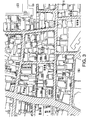
- Figure 1 shows one example of a city map in which building outlines and sidewalk shapes, etc., are drawn accurately and in detail.
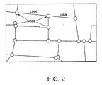
- Figure 2 shows one example of road network data in which intersections are expressed as nodes, and roads are expressed as directional vectors (links) that connect these nodes.
- road polygon data in which the road shapes of city maps are favorably reproduced can be generated by superimposing road network data of the type shown in Figure 2 on a city map of the type shown in Figure 1, and performing processing that will be described in detail below.
- Figure 3 shows an example in which road polygon data completed in this manner is painted in by hatching, and displayed superimposed on the city map data shown in Figure 1.
- road polygon data which shows precise agreement with the complicated road shapes of the city map is obtained.
- the roads can be painted in as shown in this figure, a city map that is easy to see can be provided.
- the respective roads (links between intersections) of the road network data shown in Figure 2 can be associated in a one-to-one correspondence with the respective road respective road polygons (road polygons extending from intersection to intersection) of the road polygon data painted in by hatching in Figure 3.
- the route found as a result of this search can be expressed on the city map by the painted-in roads themselves rather than being expressed by simple zigzag lines connecting the centers of intersections as in conventional systems.
- Figure 4 shows the system construction of a road data preparation device constituting one embodiment of the present invention.
- This road data preparation device is typically a programmed general-use computer.
- the central processing unit 1 of this computer performs simple road polygon preparation processing 3, scissors data preparation processing 6 and road polygon preparation processing 8 according to programs.
- a road network data base 2 which stores road network data that expresses intersections and roads of the types shown for example in Figure 2 as nodes and links, and a city map data base 5 which stores city map data in which building outlines and sidewalk shapes, etc., such as those shown in Figure 1 are drawn in detail, are accommodated in the memory of this computer as raw-material data.
- the central processing unit 1 first performs simple road polygon preparation processing 3.
- line-segment data (link data between respective intersections) for respective roads included in the road network data stored in the road network data base 2 is expanded in the width direction to an extend exceeding the width dimension of the respective roads in the city map data 5, so that simple road polygon data, which covers the respective road regions in the city map data 5 with a slight excess margin, is prepared for each road.
- the simple road polygon data that has been prepared for each road is collected and stored in the simple road polygon data base 4 of the memory.
- the central processing unit 1 next performs scissors data preparation processing 6.
- scissors data data indicating cutting lines for trimming
- This processing 6 scissors data which is used form correct road shapes by trimming the simple road polygon data for the respective roads is prepared on the basis of line segment data such as road outlines and building outlines, etc., contained in the city map data that is stored in the city map data base 5.
- the scissors data thus prepared for the respective roads is collected and stored in the scissors data base 7 of the memory.
- the central processing unit 1 next performs road polygon preparation processing 8.
- this processing 8 the simple road polygon data for respective roads stored in the simple road polygon data base 4 is trimmed using respective scissors data from the scissors data base 7, thus preparing road polygon data that expresses the accurate road shapes of respective roads.
- the road polygon data that is thus prepared is collected and stored in the road polygon data base 9 of the memory.
- Figure 5 shows the procedure of the abovementioned simple road polygon preparation processing 3.
- road network data for the object region is first read in from the road network data base 2.
- intersections and roads are respectively expressed as nodes and links.
- one link (road) 11 is a zigzag line that connects two adjacent nodes (intersections) 13 and 15, and this zigzag line is expressed using a plurality of straight line segments L1, ... Ln that connect the initial-end node 13, respective intermediate shape element points (flexure points) 17, 17... and the final-end node 15 in that order.
- Such road network data can be prepared from national road data on a 1 : 25,000 scale.
- the simple road polygon preparation processing 3 next expands the respective line segments L1, ... Ln of the respective links shown in Figure 5 (a) in the direction of the width dimension (i.e., the direction perpendicular to the line segments) as shown in Figure 5 (b), so that element polygons (e. g., rectangles) 21 i that encompass the respective line segments Li are created. Furthermore, as is shown in Figure 5 (c), the starting points and final points (shape element points at both ends) 23i and 23i+1 of the respective line segments Li are expanded in all directions to a greater extent than the respective line segments Li, thus creating element polygons (e.
- a single simple road polygon 27 that encompasses the link in question (shown in Figure 5 (e)) is created by calculating the sum of the regions of the abovementioned element polygons 251, 211, ... 21 n, 25n+1.
- This simple road polygon 27 roughly expresses the shape of a single road that has a width dimension. Afterward, this simple road polygon 27 is shaped to the accurate shape of the road shown in the city map data by being trimmed (in other words, by having excess portions removed). Accordingly, it is necessary that this simple road polygon 27 have a width dimension that is greater than that of the accurate road shown in the city map data, so that the region of the accurate road is completely encompassed. For this reason, the element polygons 21i of the respective line segments Li are expanded in the abovementioned expansion processing so that these element polygons 21i have a width dimension that is slightly greater than the width dimension of the accurate road shown in the city map data. For example, the amount of this expansion can be determined by the method shown in Figure 6.
- the line segments Li of the respective links of the road network data are superimposed on city map data 31.
- perpendicular lines are extended on both sides from a plurality of ground points of the line segments Li as indicated by the arrows, and the lengths d1, d2, ... to the points where these perpendicular lines first cross line segments on the city map are measured.
- the lengths d1, d2 ... of these perpendicular lines are viewed as values that represent the width to the edge lines on both sides from the center line of the road in question in road sections located in the vicinities of the respective ground points. Accordingly, for each side of the road, a weighted average is calculated by weighting the lengths d1, d2 ...
- Element polygons that completely encompass the road in question on the city map can be prepared by expanding the line segments Li in the upward and downward directions by distances W3 and W4 that are greater by an appropriate amount than the road widths W1 and W2 thus determined. Furthermore, as was described above, element polygons that are expanded to a greater extent than the line segments Li are created ad the final points, starting points and nodes of the line segments Li; the reason for this is to ensure that the turning angles and intersections within these element polygons (these usually have a width that is greater than the width of straight portions of the road) are securely encompassed.
- a certain element polygon G1 consists of polygon line segments (f11, f12, ... f16) that are formed into a closed loop; furthermore, another element polygon G2 consists of polygon line segments (f21, f22, ... f25) that are formed into a closed loop, and the element polygons G1 and G2 are partially superimposed.
- the second element polygon G2 is cut by a line segment of the first element polygon G1.
- the line segment f22 of the second element polygon G2 is cut, so that new line segments f22' and f22" are generated.
- the line segment f25 is also cut, so that new line segments f25' and f25" are generated.
- the first element polygon G1 is cut by a line segment of the second element polygon G2.
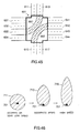
- the simple road polygon In the case of roads that show a closed-loop shape on maps, such as (for example) spiral on-ramps leading to high-speed roadways, the simple road polygon has a cut-out area within the region of the polygon. In such cases, it is necessary to distinguish between external polygons that define the external shape of the simple road polygon, and cut-out polygons that define the cut-out area, in the process of preparing the simple road polygon.
- Figure 8 shows the method used to distinguish external polygons and cut-out polygons in such cases.
- a simple road polygon 43 consisting of a first line segment group A (a1, ... a9), and a simple road polygon 45 consisting of a second line segment group B (b1, ... b3), are generated.
- one of the simple road polygons is the external polygon of the road in question, while the other is the cut-out polygon. Accordingly, processing is performed in order to determine which of these simple road polygons 43 and 45 is the external polygon. Specifically, one representative point on a line segment is first selected for each of the abovementioned simple road polygons 43 and 45.
- the single polygon in which the representative point in question is present outside the regions of all of the other polygons is determined to be the external polygon of the road in question, and all of the other polygons are determined to be cut-out polygons.
- the representative point of the polygon 43 is a1 and the representative point of the polygon 45 is b1
- the representative point b1 of the polygon 45 is present inside the other polygon 43
- the representative point a1 of the polygon 43 is present outside all of the other polygons 45.
- the polygon 43 is the external polygon
- the polygon 45 is a cut-out polygon.
- Such a distinction between external polygons and cut-out polygons is made each time that the sum of the regions of pairs of element polygons is calculated using the method shown in Figure 7.
- the calculation of the sums of regions of adjacent element polygons is repeated from the starting point node to the final point node of one road, so that a simple road polygon that encompasses the road in question (as shown in Figure 5 (e)) is completed. This is performed for all of the link data of the road network data, and the results are stored in the simple road polygon data base 4.
- scissors data defines cutting lines used to shape simple road polygons (which are prepared so that these shapes are slightly larger than actual road shapes) into accurate road shapes by trimming these simple road polygons. Accordingly, scissors data, i.e., cutting lines, ideally run along the accurate external shapes of the roads, and do not invade the internal regions of the roads.
- "Scissors" data preparation processing 6 is processing which is used to prepare scissors data that is as close to ideal as possible.
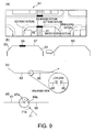
- Figure 9 illustrates the procedure of scissors data preparation processing 6.
- a method in which (for example) city map data is divided into numerous segment by means of an appropriately fine mesh, the object of extraction is limited exclusively to shape lines that are present inside the segments through which respective links of the road network data pass when these links are superimposed on the city map, and the object of extraction is further limited exclusively to shape lines contained in rectangular regions that are defined by the maximum values and minimum values of the xy coordinates of the respective links, can be adopted in order to limit the object of extraction exclusively to shape lines that are located in the vicinity of the respective roads (i.e., in order to exclude shape lines that have no connection with the outline shapes of the respective roads).
- the various attribute shape lines that make up the external lines of roads in city map data 51 consist of independent line segment data that is not mutually connected.
- the outlines of roads are not single line segments in the city map data, but are instead made up of collections of numerous scattered independent line segments.
- connectable line segments 53, 55, 57 and 59 are next selected from the various extracted shape lines, and these line segments are connected to each other so that a single line segment 63 is created as shown in Figure 9 (b).
- connectable line segments refers to line segments which are such that the coordinates of one end point (final point or starting point) of one line segment and the coordinates of one end point of another line segment coincide completely, and line segments which are such that the distance between one end point of one line segment and one end point of another line segment is within the range of a specified permissible value ⁇ (in short, line segments which are sufficiently close to each other so that these line segments can be viewed as making up a single line segment), as in the case of the line segments 65 and 67 shown in Figure 9 (c).
- outline data for the respective roads is contained with fairly good precision in the connected line segment data.
- This processing is performed for the respective roads in the city map data, and the connected line segment data for each road that is obtained as a result is stored in the scissors data base 7 as scissors data for the simple road polygons of the respective roads.
- proximate shape lines When proximate shape lines are connected to each other, such connection is not limited to cases in which the end points of two line segments are located in close proximity to each other; there are often cases in which the end points of three or more line segments are located in close proximity to each other.
- line segments 73, 75, 77 and 79 are present in the vicinity of the same road as shown in Figure 10 (a).
- the end points of two line segments 73 and 75 are in close proximity to each other in one location A, and that the end points of three line segments 75, 77 and 79 are in close proximity to each other in another location B.
- the two line segments 73 and 75 are simply connected into a single line segment as described above.
- the road polygon preparation processing 8 is processing which creates road polygons that express the accurate outline shapes of the respective roads by using the scissors data for these roads to trim the simple road polygons for the respective roads.
- simple road polygon data for the respective roads is read in from the simple road polygon data base 4
- scissors data for the respective roads is read in from the scissors data base 7
- the respective scissors data for all of the roads is investigated on a road by road basis in order to ascertain whether or not this data passes through the simple road polygon data for the roads.
- five lines of scissors data 91, 93, 95 and 97 pass through the simple road polygon 81.
- the simple road polygon 81 is cut using the respective scissors data passing through this simple road polygon.
- the simple road polygon is divided into two line segment groups. Of these line segment groups, the line segment group that encompasses the nodes of the road network data (i.e., on the inside of the road) is allowed to remain, while the other line segment group (i.e., on the outside of the road) is discarded.
- the scissors data is also cut by the line segments of the simple road polygon, and of the plurality of line segment groups of semiconductor that result from this division, only the line segment group that is enveloped by the simple road polygon is allowed to remain. Then, a new simple road polygon from which the portions on the outside of the road have been cut away along the scissors data is obtained by connecting the remaining line segment group of the simple road polygon and the remaining line segment group of the scissors data.
- road polygons that show precise agreement with the shapes of roads expressed on city maps can be automatically prepared.
- this data shows good compatibility with road network data, and the link relationships with large-area maps, etc., prepared from road network data are also clear.
- road connection information held in road network data can also be associated with the road polygons and thus retained.
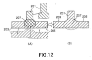
- FIG. 12 (A) An example of the construction of such road map data is shown in Figure 12 (A), and a road image displayed on a screen on the basis of this road map data is shown in Figure 12 (B).
- this road map data is constructed from a plurality of road polygons 201, 203 and 205.
- the regions of the intersections are not distinguished from the road polygons 201, 203 and 205, but are instead included in the road polygons 201, 203 and 205.
- the region 207 where the plurality of road polygons 201, 203 and 205 overlap each other is visually recognized as an intersection by a human observer.
- the computer application that utilizes the abovementioned road map data cannot accurately distinguish or indicate intersection regions and road regions in the road map data.
- intersections are expressed as independent polygons that are accurately distinguished from the road polygons in the road map data based on polygons, in order to increase the visibility of the intersection areas on the route.
- intersections are included in the road polygons as shown in Figure 12 (A), then in cases where (for example) a route that turns from the road polygon 201 to the road polygon 203 is displayed, the region 207 where these two road polygons 201 and 203 overlap will have an unnatural shape as an intersection, so that the visibility of this intersection is poor.
- route search processing which determines the route from starting point to destination is performed on the basis of conventional road network data on (for example) a scale of 1/25,000 (intersections are expressed by nodes (coordinate points), and roads are expressed by directional vectors that connect these nodes). Consequently, in order to display a route using the abovementioned polygons, it is necessary that the intersection polygons and road polygons in the road map data have a data association with the intersection nodes and road vectors in the road network data.
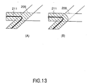
- a display in which only the operating lanes within the intersection 209 are expressed as a guide route 213 as shown in Figure 13 (B) is easier to comprehend than a display in which the entire region of the intersection 209 is displayed as a guide route 211 as shown in Figure 13 (A).
- the only data used is intersection polygon data in which the entire region of an intersection is defined as one polygon, an easy-to-comprehend route display of the type shown in Figure 13 (B) cannot be displayed.
- Figure 14 shows the system construction of a device constituting one embodiment of the present invention which is used to prepare road map data in which roads and intersections are expressed by respective polygons.
- This road map data preparation device is typically a programmed general-use computer.
- the central processing unit 301 of this computer performs pre-processing 304, intersection polygon preparation processing 305, road polygon correction processing 308 and guiding intersection polygon preparation processing 310 in accordance with programs.
- a road network data base 302 which stores road network data in which intersections and roads are expressed as nodes and links
- a city map data base 303 which stores city map data based on line segments in which building outlines and sidewalk shapes, etc., are drawn in detail
- a road polygon data base 307 which stores road polygon data (including intersection regions as shown for example in Figure 12) prepared (for example) by the method already described with reference to Figures 4 through 11 on the basis of road network data and city map data, are accommodated in the memory of this computer as raw-material data.
- the central processing unit 301 first performs pre-processing 304.
- This pre-processing 304 accesses the road network data and city map data in the memory, establishes agreement between the map space coordinates of the road network data and the map space coordinates of the city map data, and respectively divides the road network data and city map data into numerous cells (numerous rectangular regions of a uniform small size) so that the respective types of map data can be controlled in cell units.
- intersection polygon preparation processing 305 prepares intersection polygon data on the basis of the road network data and city map data obtained following pre-processing 304, and stores the intersection polygon data thus prepared in an intersection polygon data base 306.
- the central processing unit 301 performs road polygon correction processing 308.
- This processing 30 corrects the road polygon data (including intersection regions) read out from the road polygon data base 307 using intersection polygon data from the intersection polygon data base 306, thus preparing road polygon data that does not include intersection regions (hereafter referred to as "pure road polygon data"); the pure road polygon data thus prepared is then stored in a pure road polygon data base 309.
- the central processing unit 301 performs guiding intersection polygon preparation processing 310.
- this processing 310 prepares guiding intersection polygon data in which two sets of road polygon data that are connected to the same intersection are smoothly linked as shown in Figure 13 (B).
- the guiding intersection polygon data thus prepared is then stored by this processing 310 in a guiding intersection polygon data base 311.
- intersection polygon preparation processing 305 intersection polygon preparation processing 305
- road polygon correction processing 308 guiding intersection polygon preparation processing 310
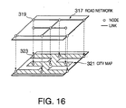
- road network data from the data base 302 and city map data from the data base 303 are accessed in the memory of the central processing unit 301.
- the map region 313 expressed by the road network data and the map region 315 expressed by the city map data show disagreement in the coordinate space (e. g., in the latitude and longitude of the coordinate origin at the lower left end).
- the coordinate spaces of these two map regions 313 and 315 are caused to coincide as follows: specifically, the positional discrepancy between the two coordinate spaces ( ⁇ x, ⁇ y) is calculated as follows.
- ⁇ x longitude of origin of road network map region - longitude of origin of city map region
- ⁇ y latitude of origin of road network map region - latitude of origin of city map region
- the conversion functions Fix() and Fiy() are linear conversion functions that use ( ⁇ x, ⁇ y) and the maximum coordinates (Xi, Yi) at the upper right ends of the respective map regions 313 and 315.
- the city map data and road network data accessed in the memory are respectively divided into numerous cells (small rectangular regions) and controlled in cell units in order to reduce the amount of geometrical calculation required in the subsequent intersection polygon preparation processing 305.
- the respective sets of road map data have a map element control table 329 in which pointers to all of the map elements 327 present inside the entire map region 325 covered by the data are registered.
- the entire map region 325 for the respective sets of map data is divided into numerous cells 331 of a uniform size.
- aggregates of pointers to map element in the map element control table 329 are classified into aggregates of pointer to map elements present inside the respective cells 331, and indices 335 for the respective cells are assigned to the pointer aggregates 333 on a cell by cell basis.
- indices 335 for the respective cells are assigned to the pointer aggregates 333 on a cell by cell basis.
- the table 337 thus prepared in which map elements are controlled on a cell by cell basis, will be referred to below as an "index table”.
- Such an index table 337 is prepared for each set of road network data and city map data.
- the optimal value of the cell size is determined on a case by case basis.
- intersection polygon preparation processing 305 will be described with reference to Figures 18 through 25.
- intersection polygon preparation processing 305 all of the node data contained in the road network data is first extracted in order. Then, with attention directed toward the individual nodes that have been extracted, the cell 341 to which the node of interest 339 belongs is determined using the index table 337 prepared by the pre-processing 304, as is shown in Figure 18 (A). Then, as is shown in Figure 18 (B), the cell of the city map which has the same cell number as the cell 341 to which the node of interest 339 belongs, and all of the cells adjacent to this cell, are selected as the object region 343.
- the node of interest 339 on the road network map and the links L1 through L4 that are connected to this node of interest 339 are superimposed on map elements such as building outlines, road outlines and sidewalk boundaries, etc., in the object region 343 of the city map as shown in Figure 19.
- a search is made for the shape element points 347 of the map elements on the city map from a circular region (search range) 345 with a specified radius of R centered on the center of gravity of the node.
- the term “center of gravity of the node” refers to the node of interest 339 itself, or the center of gravity calculated from all of the shape element points present within a specified distance range from the node of interest 339 (this is advantageous in cases where the node of interest 339 is considerably shifted from the actual center of the intersection).
- the node of interest 339 is set as the center of gravity of the node in order to make this node easier to comprehend.
- shape element point refers to end points and corner points of the map elements (zigzag line segments) on the city map based on line segments.
- the angles ⁇ 1 through ⁇ 4 between the links L1 through L4 that are connected to the node of interest 339 are first determined (in other words, the search region 345 is divided by links L1 to L4 into a plurality of sectors S1 through S4).
- ⁇ 1 is the angle between L1 and L2
- ⁇ 2 is the angle between L2 and L3
- ⁇ 3 is the angle between L3 and L4
- ⁇ 4 is the angle between L4 and L1.
- Figure 20 shows an example of the search results in the range of the initial angle ⁇ 1 (i.e., the initial sector S1). For each of the shape element points P1, P2, P3 ... found as a result of a search of this sector S1, the distance d1, d2, d3 ... from the node center of gravity 339 is calculated, and these results are accumulated in a search result table 349 as shown in Figure 21. When these distance calculations have been completed for all of the shape element points within the sector S1, the search result table 349 shown in Figure 21 is sorted in ascending order of distance, and the shape element point Pj which has the shortest distance within the sector S1 is found. For example, in Figure 20, it is assumed that the distance d3 of the shape element point P3 is the shortest distance.
- a circular-arc-form belt range B1 which extends from the shortest distance d3 to a distance d3 + ⁇ produced by adding a specified permissible width ⁇ to the shortest distance d3 is set, and the shape element points P1 through P5 that are present within this belt range B1 are extracted as shape element points that make up an intersection polygon.
- the extracted shape element points P1 through P5 are registered in an intersection polygon element table 351.
- the respective angles ⁇ 1 through ⁇ 5 of the shape element points P1 through P5 i.e.
- angles of the respective shape element points measured in (for example) the clockwise direction with the node center of gravity 339 as the center of rotation and (for example) the direction of the x axis taken as an angle of 0) are also registered in the intersection polygon element table 351.
- intersection polygon data is repeated for all of the nodes of the road network data.
- intersect point regions are removed from the road polygon data including intersection regions that is accumulated in the road polygon data base 307, using the intersection polygon data that is accumulated in the intersection polygon data base 306.
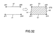
- the tangential line C1 between the intersection polygon 357 of the node of interest 339 and the pure road polygon 361 of the link L1 is first extracted as shown in Figure 28.
- the tangential lines C2, C3 and C4 are also extracted for the other road polygons 361, 363, 365 and 367 that contact the intersection polygon 357, and hypothetical tangential lines c2, c3 and c4 are determined.
- two hypothetical tangential lines are arbitrarily extracted from these hypothetical tangential lines c1, c2, c3 and c4.
- an intersection K1 of extension lines of the hypothetical tangential line c1 and hypothetical tangential line c2 is determined next as shown in Figure 30.
- the angle formed by the hypothetical tangential lines c1 and c2 at this intersection K1 is designated as ⁇ .
- this angle ⁇ is equal to or greater than a specified value
- the distances d1 and d2 to the outside end points p12 and p22 of the hypothetical tangential lines c1 and c2 from the intersection K1 are calculated. Furthermore, a circular arc a1 that is centered on the intersection K1 is extended from the outside end point p12 of the hypothetical tangential line c1 that has the longer distance d1 toward the other hypothetical tangential line c2, and this circular arc a1 is stopped at the intersection K2 between the circular arc a1 and an extension line of the hypothetical tangential line c2.
- the circular arc a1 thus determined from the outside end point p12 to the intersection K2 is used as one outlining line of the guiding intersection polygon.
- the outlining lines of the intersection polygon 355 are used "as is” as the other outlining lines of the same guiding intersection polygon.
- the region that is located closer to the intersection K1 when the intersection polygon 355 is cut into two regions by the circular arc a1 is used as the guiding intersection polygon.
- the guiding intersection polygon 371 shown in Figure 31 is completed.
- the abovementioned processing used to prepare guiding polygons is performed for all combinations of two road polygons that can be selected from an aggregate of N road polygons. Accordingly, for example, in the case of a four-way intersection such as that shown in Figure 33 (A), six guiding intersection polygons 381, 383, 385, 387, 388 and 389 such as those shown in Figures 33 (B) through 33 (G) are prepared. The data for the guiding intersection polygons thus prepared is accommodated in the guiding intersection polygon data base 311. The abovementioned guiding intersection polygon preparation processing 310 is repeated for all of the intersections.
- intersection polygon data, pure road polygon data and guiding intersection polygon data prepared as described above can be utilized in various applications.
- One of these applications is route guidance in car navigation.
- the route is indicated by a zigzag line 391.
- the route can be displayed as a route polygon 393, which connects pure road polygon data and guiding intersection polygon data, and which is close to the actual route shape.
- Another application is the display of traffic jam on roads in car navigation.
- the method used to display traffic jam on roads will be described with reference to Figures 35 through 37.
- traffic jam information provided from the VICS (Vehicle Information and Communication System) (registered trademark) of the Japanese Road Traffic Information and Communication System Center (Incorporated) designates the starting ends and final ends of tailbacks of cars for respective inbound and outbound traffic lanes using the respective distances from the initial and final intersections.
- VICS Vehicle Information and Communication System
- Figure 35 shows a case in which the final end of a tailback of cars is designated as H meters from the intersection of the node N1 for the inbound traffic lane (the traffic lane in which traffic runs toward the node N1 from the node N2).
- straight lines 409 and 411 which are perpendicular to the link L1 are extended on both sides of the link L1 from the final end point of tailback of cars Ph. Then, the intersections of these perpendicular lines 409 and 411 with the intersection polygon 403 of the node N1, the pure road polygon 405 of the link L1 and the intersection polygon 407 of the node N2 are determined. Then, the following processing operations (1) through (3) are performed in that order.
- the polygon regions judged to be tailbacks of cars i.e., the road and intersection polygon regions 405A, 403 and 401 located downstream from the perpendicular lines 409 and 411 at the final end point Ph of the tailback of cars, are painted in with a color or texture that indicates a tailback of cars, as shown by the hatching, and these regions are displayed in this manner.
- the polygon regions judged to be tailbacks of cars i.e., the road and intersection polygon regions 405A, 403 and 401 located downstream from the perpendicular lines 409 and 411 at the final end point Ph of the tailback of cars, are painted in with a color or texture that indicates a tailback of cars, as shown by the hatching, and these regions are displayed in this manner.
- polygon data 411 through 433 for roads and intersections distinguished by traffic lanes can be prepared in the case of a single road that has individual traffic lanes.
- the display of traffic jams and the display of routes can be performed according to traffic lanes.
- a traffic jam area in one traffic lane is indicated by hatching.
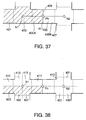
- the positions of the nodes 511 and 513 and link 515 in the road network data do not always match (in terms of position) the intersection polygons 501 and 505 and pure road polygon 509 prepared from the city map. Accordingly, the geometrical centers of gravity 503 and 507 of the intersection polygons are first respectively determined, and these geometrical centers of gravity 503 and 507 are defined as the new nodes of the respective intersection polygons 501 and 505.
- lines 541 through 544 that are perpendicular to the link 515 are extended to both sides of the link 515 from a plurality of positions located at appropriate intervals between one intersection 531 and another intersection 533 on the link 515. Then, the intersections 561 through 568 between the respective perpendicular lines 541 through 544 and outlining lines 551 and 553 other than the abovementioned tangential lines 521 and 523 of the pure road polygon 509 are determined.
- each of the abovementioned perpendicular lines 541 through 544 and tangential lines 521 and 523 is equally divided by the number of traffic lanes N that this road possesses.
- the number of traffic lanes N is 2; accordingly, the respective perpendicular lines 541 through 544 and the respective tangential lines 521 and 523 are divided into two equal parts by the respective center points 572 through 575, 571 and 576 of the lines. Then, a line segment 581 which successively passes through these center points is determined, and the pure road polygon 509 is divided into two sub-road polygons 591 and 593 by this line segment 581. The two sub-road polygons 591 and 593 thus obtained are registered in the road map data as traffic lane polygons that express the two traffic lanes of this road.
- the respective center points (indicated by empty circles in Figure 42) of the abovementioned perpendicular lines 541 through 544 and the abovementioned tangential lines 521 and 523 are determined; then, line segments (indicated by broken lines in Figure 42) that successively pass through these center points are determined, and these line segments are registered in the road map data as vehicle guide lines for the respective traffic lane polygons 591 and 593.
- a plurality of traffic lane polygons and guide lines are also set in the respective intersection polygons that contact roads that have two or more traffic lanes.
- Figure 43 shows an example in which two traffic lane polygons 621 and 623 (used for straight-ahead traffic within the intersection) which connect the two traffic lane polygons 611 and 613 of the upper road in the figure with the two traffic lane polygons 615 and 617 of the lower road in the figure are set in an intersection polygon 601.
- a plurality of traffic lane polygons (used for straight-ahead traffic within the intersection) which connect the plurality of traffic lanes 631 through 634 of the left-hand road in the figure with the plurality of traffic lanes 641 through 644 of the right-hand road in the figure are also similarly set.
- the broken lines in the figure indicate vehicle guide lines set within the respective traffic lane polygons.
- Figure 44 shows an example in which traffic lane polygons 651 through 654 for left turn use in the case of driving on the left (right turn use in the case of driving on the right) are prepared within an intersection polygon 601.
- the outermost traffic lane polygons 631, 641, 634 and 644 of the road running in the left-right direction in the figure and the outermost traffic lane polygons 611, 613, 615 and 617 of the road running in the vertical direction in the figure are respectively connected by the traffic lane polygons 651 through 654 within the intersection polygon 601.
- the curved outlines of the traffic lane polygons 651 through 654 within the intersection may be expressed by clothoid curves, circular arcs, elliptical arcs, parabolic curves, hyperbolic curves or zigzag lines, etc.
- the broken lines in the figure indicate vehicle guide lines that are set within the respective traffic lane polygons.
- Figure 45 shows an example in which traffic lane polygons 661 and 663 for right turn use in the case of driving on the left (or for left turn use in the case of driving on the right) are prepared with the intersection polygon 601.
- the inside traffic lane polygons 633 and 642 of the road that runs in the left-right direction in the figure and the inside traffic lane polygons 613 and 617 of the road that runs in the vertical direction of the figure are respectively connected by the traffic lane polygons 661 and 663 inside the intersection.
- the curved outlines of the traffic lane polygons 661 and 663 within the intersection may be expressed by clothoid curves, circular arcs, elliptical arcs, parabolic curves, hyperbolic curves or zigzag lines, etc.
- the broken lines in the figure indicate vehicle guide lines that are set within the respective traffic lane polygons.
- traffic lane polygons required for straight-ahead traffic and left and right turns within respective intersection polygons are thus prepared in advance, and guide lines are set within the respective traffic lane polygons, vehicle guidance at intersections can be accurately performed.
- the traffic lane polygons within the intersections shown in Figures 43 through 45 are merely examples used for the purpose of illustration.
- the types of traffic lane polygons within intersections that should be prepared vary according to the number of traffic lanes in the intersecting roads, the direction of travel in the respective traffic lanes (this direction is fixed in some cases, and varies according to the time of day in other cases), and the traffic regulations that are applied, etc.
- the preparation of the intersection polygons, pure road polygons and traffic lane polygons described above can be accomplished using either a static method or a dynamic method.
- the static method is a method in which all of the intersection polygons, pure road polygons and traffic lane polygons are prepared in advance for the entire map region, and accommodated in a map data base. When a road map is to be displayed, polygons for the region that is to be displayed can be read out and displayed.
- the dynamic method is a method in which the polygons are not all prepared beforehand; instead, each time that a road map is to be displayed, only the poiygons necessary for the required region are prepared from city map data and road network data.
- the static method is usually used in road map display devices that have a large memory capacity.
- the dynamic method is used in map display devices in which it is difficult to guarantee a sufficiently large memory capacity, such as car navigation devices.
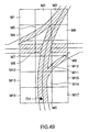
- Figure 46 illustrates one principle that is used to determine the extent to which the range of the object region of polygon preparation should be limited when polygon map data is dynamically prepared in a car navigation device.
- the object region of polygon preparation is a more or less circular region 711 of a specified radius, which is more or less centered on the position 701 of the automobile (the triangular marks in the figure indicate that the vehicle is running toward the top of the figure).
- a more or less elliptical or egg-shaped region 713 which includes the position 701 of the automobile in the rear end portion of said region, and which extends further in the direction of advance of the automobile, is taken as the object region.
- an elongated elliptical or egg-shaped region 715 which includes the position 701 of the automobile in the rear end portion of said region, and which extends even further in the direction of advance of the automobile, is taken as the object region.
- Figures 47 through 49 show the method used to select the concrete object region of polygon preparation according to the abovementioned principle.
- Maps used for car navigation are generally controlled by being divided into numerous small-area rectangular regions (mesh regions). Accordingly, the object region in which road or intersection polygons are dynamically produced is an aggregate of a plurality of mesh regions.
- the mesh region M0 that includes the current position 701 of the automobile (the triangular mark indicates that the automobile is moving upward in the figure) and (for example) the eight adjacent mesh regions M1 through M8 that surround the mesh region M0 are taken as the object of polygon preparation. Then, these mesh regions M0 through M8 are processed with priority given to mesh regions in which there is a higher probability that the automobile will be present at a subsequent point in time (i.e., a higher probability that the driver will require data for these mesh regions), in accordance with the direction of advance of the automobile (or the direction in which the automobile is pointing when stopped).
- road and intersection polygons are prepared by processing the mesh region M0 that includes the current position 701.
- the mesh region M2 which is located in front of the mesh region M0 of the current position is processed.
- the mesh regions M1 and M3 in either order), which are located obliquely in front on the left and right with respect to the direction of advance.
- the mesh regions M4 and M5 in either order which are located to the left and right of the mesh M0 of the current position.
- mesh regions M6 and M7 in either order
- the final mesh region to be processed is the mesh region M7, which is located to the rear of the mesh region M0 of the current position.
- the first mesh region to be processed is the mesh region M0 of the current position of the automobile.
- the next mesh region to be processed is the mesh region M5 which is located in front of the mesh region M0 of the current position.
- Next to be processed are the mesh regions M2, M4 and M6 (in any order), which are respectively located further in front of the mesh region M0 and obliquely in front of the mesh region M0 on the left and right of the mesh region M0.
- the next regions to be processed are the mesh regions M1 and M3 which are located even further in front of the mesh region M0 on the left and right of the mesh region M0.
- the final regions to be processed are the mesh regions M7 and M8 (in either order), which are adjacent to the mesh region M0 on the left and right.
- the system is arranged so that only roads and intersections of the same type as the road on which the automobile is currently traveling are selected, or so that roads and intersections of a type with a predetermined high priority are selected in addition to roads and intersections of the same type as the road on which the automobile is currently traveling.
- types of roads refers proper names of roads such as "National Route 10" and "Yasukuni-dori”, and names of types of roads such as “national highways", “prefectural roads”, “municipal roads”, “roads exclusively for use by automobiles” and “high-speed thoroughfares”, etc. These road types are obtained from attribute data contained in the road network data.
- the numbers or types of roads and intersections that are converted into polygons can be increased or decreased in accordance with the operating speed v of the automobile.
- the average number of polygons m to be prepared for each mesh region is determined so that the polygon conversion processing for all of the N mesh regions that constitute the object of processing can be completed within the time X/v required for the automobile to travel a distance equal to one mesh region. Then, the road types that are the object of polygon conversion are selected so that the average number of polygons actually prepared for each mesh region does not exceed the abovementioned m.
- Figure 50 illustrates a road map display device which constitutes one embodiment of the present invention.
- This road map display device 800 has city map data 801, polygonal road network data 803, and a display part 805.
- the polygonal road network data 803 is data in which the node shape data in conventional road network data constructed from nodes and links is changed from point data to intersection polygon data prepared by the method of the present invention, and the link shape data is changed from line segment data to pure road polygon data prepared by the method of the present invention.
- this polygonal road network data 803 may also include lane polygon data formed by dividing the abovementioned pure road polygons, and lane polygon data within intersections, which is set inside intersection polygons.
- the display part 805 draws city map images from the city map data 801, and also draws images of road polygons and intersection polygons, which have shapes matching the shapes of roads and intersections on the city map, from the polygonal road network data 803 (if necessary, these polygons may be painted in with specified colors). Furthermore, this display part 805 displays images of road polygons and intersection polygons superimposed on the city map image. As a result, regions showing good conformity to the shapes of roads and intersections on the city map can be displayed as roads and intersections.
- the display part 805 performs a route search function in which the polygonal road network data 803 is used to search for a road route from the starting location to the destination; moreover, the display part 805 also uses the polygonal road network data 803 to correct the current position of the automobile so that this position is located inside certain road polygons or certain intersection polygons.
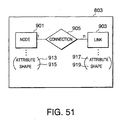
- Figure 51 shows the structure of the polygonal road network data 803.
- the polygonal road network data 803 includes node data 901 which expresses individual nodes (intersections), link data 903 which expresses individual links (roads), and connecting data 905 which expresses the connections between nodes and links.
- the connection data 905 indicates connection relationships between nodes and links, such as the fact that link data 903 for n specified links is connected to node data 901 for one specified node.
- Each item of node data 901 includes attribute data 913 which indicates attributes of each node, and shape data 915 which indicates the shape of each node.
- Each item of link data 903 includes attribute data 917 which indicates attributes of each node, and shape data 919 which indicates the shape of each node.
- the connection data and attribute data of conventional road network data used in the preparation of road polygon data and intersection polygon data can be used as the connection data 905 and attribute data 913 and 917.
- the node shape data 915 is the intersection polygon data for the node in question
- the link shape data 919 is the pure road polygon data for the link in question.
- the abovementioned polygonal road network data 803 is data in which the conventional point data used as shape data for the respective nodes in conventional road network data is replaced by intersection polygon data, and the conventional line segment data used as shape data for the respective links is replaced by pure road polygon data. Accordingly, in cases where processing such as route search and map matching, etc., is performed using the abovementioned polygonal road network data 803 in a car navigation system, etc., conventional route search algorithms and the basic portions of conventional map matching using convention road network data can be applied. Furthermore, the road map images prepared using such polygonal road network data 803 show good matching with city map images in terms of the shapes and positions of roads and intersections; accordingly, such images are easily visible to the user.
Applications Claiming Priority (5)
| Application Number | Priority Date | Filing Date | Title |
|---|---|---|---|
| JP1537299 | 1999-01-25 | ||
| JP1537299 | 1999-01-25 | ||
| JP18997499 | 1999-07-05 | ||
| JP18997499 | 1999-07-05 | ||
| EP00901335A EP1182611A4 (fr) | 1999-01-25 | 2000-01-20 | Dispositif et procede de creation et d'utilisation de donnees sur une carte routiere exprimees par des polygones |
Related Parent Applications (1)
| Application Number | Title | Priority Date | Filing Date |
|---|---|---|---|
| EP00901335A Division EP1182611A4 (fr) | 1999-01-25 | 2000-01-20 | Dispositif et procede de creation et d'utilisation de donnees sur une carte routiere exprimees par des polygones |
Publications (2)
| Publication Number | Publication Date |
|---|---|
| EP1450309A2 true EP1450309A2 (fr) | 2004-08-25 |
| EP1450309A3 EP1450309A3 (fr) | 2005-07-13 |
Family
ID=26351498
Family Applications (2)
| Application Number | Title | Priority Date | Filing Date |
|---|---|---|---|
| EP04004346A Withdrawn EP1450309A3 (fr) | 1999-01-25 | 2000-01-20 | Dispositif et procede de visualisation de donnees d'une carte routiere exprimees par des polygones |
| EP00901335A Withdrawn EP1182611A4 (fr) | 1999-01-25 | 2000-01-20 | Dispositif et procede de creation et d'utilisation de donnees sur une carte routiere exprimees par des polygones |
Family Applications After (1)
| Application Number | Title | Priority Date | Filing Date |
|---|---|---|---|
| EP00901335A Withdrawn EP1182611A4 (fr) | 1999-01-25 | 2000-01-20 | Dispositif et procede de creation et d'utilisation de donnees sur une carte routiere exprimees par des polygones |
Country Status (7)
| Country | Link |
|---|---|
| US (1) | US6622085B1 (fr) |
| EP (2) | EP1450309A3 (fr) |
| JP (1) | JP4875240B2 (fr) |
| KR (1) | KR100579767B1 (fr) |
| CN (1) | CN1168046C (fr) |
| TW (1) | TW504618B (fr) |
| WO (1) | WO2000043953A1 (fr) |
Families Citing this family (103)
| Publication number | Priority date | Publication date | Assignee | Title |
|---|---|---|---|---|
| JP4663136B2 (ja) * | 2001-01-29 | 2011-03-30 | パナソニック株式会社 | デジタル地図の位置情報伝達方法と装置 |
| JP4791649B2 (ja) * | 2001-05-07 | 2011-10-12 | 株式会社ゼンリン | 電子地図データ、表示制御装置およびコンピュータプログラム |
| US6917877B2 (en) * | 2001-08-14 | 2005-07-12 | Navteq North America, Llc | Method for determining the intersection of polygons used to represent geographic features |
| JP4746794B2 (ja) * | 2001-08-21 | 2011-08-10 | クラリオン株式会社 | カーナビゲーション装置、カーナビゲーション用制御プログラムを記録した記録媒体 |
| US20030132932A1 (en) * | 2001-09-17 | 2003-07-17 | Xiangheng Yang | Method for constructing polygons used to represent geographic features |
| US20040194017A1 (en) * | 2003-01-06 | 2004-09-30 | Jasmin Cosic | Interactive video interface |
| JP3997917B2 (ja) * | 2003-01-10 | 2007-10-24 | 株式会社デンソー | 地図検索装置 |
| US7463770B2 (en) * | 2003-07-21 | 2008-12-09 | Lockheed Martin Corporation | Methods and systems for detection of repeating patterns of features |
| EP1653427B1 (fr) * | 2003-08-04 | 2014-07-09 | Panasonic Corporation | Procede de communication d'information de position sur une carte numerique, programme permettant la mise en oeuvre de ce procede, produit relatif a ce programme, systeme et appareil correspondants |
| DE10343944A1 (de) | 2003-09-23 | 2005-04-14 | Robert Bosch Gmbh | Verfahren zur Darstellung von Strassendaten in digitalen Karten sowie Verfahren zur Bestimmung der Position eines Fahrzeuges |
| US20080097689A1 (en) * | 2004-08-04 | 2008-04-24 | Speedalert Pty Ltd | An information apparatus for an operator of a land or water based motor driven conveyance |
| JP4603332B2 (ja) * | 2004-10-18 | 2010-12-22 | クラリオン株式会社 | 要約地図作成装置 |
| JP4580209B2 (ja) * | 2004-10-18 | 2010-11-10 | クラリオン株式会社 | 要約地図作成装置 |
| KR100657937B1 (ko) * | 2004-12-14 | 2006-12-14 | 삼성전자주식회사 | 2차원 선형 데이터의 실시간 3차원 변환 방법 및 장치,그리고 이를 이용한 2차원 선형 데이터의 실시간 3차원시각화 방법 및 장치 |
| KR100634536B1 (ko) | 2005-01-25 | 2006-10-13 | 삼성전자주식회사 | 3차원 그래픽스 환경에서의 2차원 고가도로 데이터의 3차원 변환 방법 및 장치, 그리고 이를 이용한 3차원 그래픽스 환경에서의 2차원 고가도로 데이터의 3차원 시각화 방법 및 장치 |
| JP4790280B2 (ja) * | 2005-02-04 | 2011-10-12 | 三菱電機株式会社 | 地図データ表示装置、地図データ表示方法及びナビゲーション装置並びに地図データ表示プログラム |
| JP2006301601A (ja) * | 2005-03-23 | 2006-11-02 | Zenrin Co Ltd | 地図データ生成装置 |
| US8370054B2 (en) | 2005-03-24 | 2013-02-05 | Google Inc. | User location driven identification of service vehicles |
| EP1876411A4 (fr) * | 2005-04-25 | 2011-06-29 | Geo Technical Lab Co Ltd | Procede d'analyse de position de formation d'image |
| EP1904952A2 (fr) * | 2005-05-23 | 2008-04-02 | Nextcode Corporation | Configurations et procedes de recherche efficaces pour application a des problemes de vision artificielle en deux dimensions |
| EP1917643B1 (fr) * | 2005-07-26 | 2011-11-23 | DeCarta Inc. | Generalisation de caracteristiques dans une carte numerique |
| JP4742285B2 (ja) * | 2005-09-20 | 2011-08-10 | 株式会社ゼンリン | 地図情報作成装置及び方法、並びにプログラム |
| JP5075331B2 (ja) | 2005-09-30 | 2012-11-21 | アイシン・エィ・ダブリュ株式会社 | 地図データベース生成システム |
| US7603231B2 (en) * | 2005-11-12 | 2009-10-13 | Alpine Electronics, Inc. | Navigation method and system having improved arrival detection function for large scale destination |
| US8630768B2 (en) | 2006-05-22 | 2014-01-14 | Inthinc Technology Solutions, Inc. | System and method for monitoring vehicle parameters and driver behavior |
| US9067565B2 (en) | 2006-05-22 | 2015-06-30 | Inthinc Technology Solutions, Inc. | System and method for evaluating driver behavior |
| JP5089921B2 (ja) * | 2006-05-31 | 2012-12-05 | パイオニア株式会社 | 道路ポリゴン作成装置、方法及びプログラム |
| DE102006055958A1 (de) * | 2006-11-24 | 2008-05-29 | Siemens Ag | Verfahren und Vorrichtung zum Speichern bzw. Darstellen von vorgegebenen geometrischen Objekten und Computerprogrammprodukt |
| US7859537B2 (en) * | 2007-01-23 | 2010-12-28 | Microsoft Corporation | Evaluation of self-intersecting vector graphics objects via planar map profiles |
| DE102007009640A1 (de) * | 2007-02-26 | 2008-09-04 | Deutsches Zentrum für Luft- und Raumfahrt e.V. | Verfahren zur Hinterlegung von in digitalen Karten enthaltenen Fahrwegen |
| US8825277B2 (en) * | 2007-06-05 | 2014-09-02 | Inthinc Technology Solutions, Inc. | System and method for the collection, correlation and use of vehicle collision data |
| DE102007028401B4 (de) * | 2007-06-15 | 2011-08-25 | Navigon Ag, 20251 | Verfahren zum Betrieb einer Navigationseinrichtung |
| US8666590B2 (en) | 2007-06-22 | 2014-03-04 | Inthinc Technology Solutions, Inc. | System and method for naming, filtering, and recall of remotely monitored event data |
| US9129460B2 (en) | 2007-06-25 | 2015-09-08 | Inthinc Technology Solutions, Inc. | System and method for monitoring and improving driver behavior |
| DE102007030259A1 (de) * | 2007-06-28 | 2009-01-08 | Navigon Ag | Verfahren zum Betrieb eines mobilen Navigationsgerätes |
| US7999670B2 (en) | 2007-07-02 | 2011-08-16 | Inthinc Technology Solutions, Inc. | System and method for defining areas of interest and modifying asset monitoring in relation thereto |
| US9117246B2 (en) * | 2007-07-17 | 2015-08-25 | Inthinc Technology Solutions, Inc. | System and method for providing a user interface for vehicle mentoring system users and insurers |
| US8818618B2 (en) | 2007-07-17 | 2014-08-26 | Inthinc Technology Solutions, Inc. | System and method for providing a user interface for vehicle monitoring system users and insurers |
| US8577703B2 (en) | 2007-07-17 | 2013-11-05 | Inthinc Technology Solutions, Inc. | System and method for categorizing driving behavior using driver mentoring and/or monitoring equipment to determine an underwriting risk |
| US7920961B2 (en) * | 2007-08-29 | 2011-04-05 | Sap Ag | Method and apparatus for path planning and distance calculation |
| US7876205B2 (en) | 2007-10-02 | 2011-01-25 | Inthinc Technology Solutions, Inc. | System and method for detecting use of a wireless device in a moving vehicle |
| US20090254841A1 (en) * | 2007-11-12 | 2009-10-08 | Move Sales, Inc. | Apparatus, method, and computer program product for characterizing user-defined areas |
| US20090132469A1 (en) * | 2007-11-16 | 2009-05-21 | Urban Mapping, Inc. | Geocoding based on neighborhoods and other uniquely defined informal spaces or geographical regions |
| US20090177393A1 (en) * | 2008-01-07 | 2009-07-09 | Simone Francine Tertoolen | Navigation device and method |
| AU2008360066A1 (en) | 2008-07-30 | 2010-02-04 | Tele Atlas B.V. | Method of and computer implemented system for generating a junction view image |
| US8688180B2 (en) | 2008-08-06 | 2014-04-01 | Inthinc Technology Solutions, Inc. | System and method for detecting use of a wireless device while driving |
| DE102009019498A1 (de) * | 2009-02-10 | 2010-08-19 | Navigon Ag | Verfahren zur Erzeugung einer digitalen Straßenkarte, Navigationssystem und Verfahren zum Betrieb eines Navigationssystems |
| US8892341B2 (en) | 2009-02-13 | 2014-11-18 | Inthinc Technology Solutions, Inc. | Driver mentoring to improve vehicle operation |
| US8963702B2 (en) | 2009-02-13 | 2015-02-24 | Inthinc Technology Solutions, Inc. | System and method for viewing and correcting data in a street mapping database |
| DE102009043309A1 (de) * | 2009-02-26 | 2010-09-16 | Navigon Ag | Verfahren und Navigationseinrichtung zur Ermittlung der voraussichtlichen Fahrzeit |
| DE102010006702A1 (de) * | 2009-02-26 | 2010-09-02 | Navigon Ag | Verfahren und Vorrichtung zur Berechnung alternativer Routen in einem Navigationssystem |
| KR101609679B1 (ko) * | 2009-03-31 | 2016-04-06 | 팅크웨어(주) | 도로의 면형 데이터를 이용한 맵 매칭장치 및 그 방법 |
| KR101023502B1 (ko) * | 2009-07-22 | 2011-03-21 | 주식회사 와이드지리정보 | 수치지도 도로 생성 시스템 및 그 방법 |
| WO2011025533A1 (fr) * | 2009-08-25 | 2011-03-03 | Inthinc Technology Solutions, Inc. | Système et procédé permettant de déterminer des positions relatives d'objets en mouvement et de séquences d'objets |
| US8493407B2 (en) * | 2009-09-03 | 2013-07-23 | Nokia Corporation | Method and apparatus for customizing map presentations based on user interests |
| CN102169511A (zh) * | 2010-02-25 | 2011-08-31 | 上海市政工程设计研究总院 | 一种道路平面线形计算机辅助设计方法 |
| US8612138B2 (en) * | 2010-09-15 | 2013-12-17 | The University Of Hong Kong | Lane-based road transport information generation |
| EP2455714B1 (fr) * | 2010-11-18 | 2019-01-23 | Harman Becker Automotive Systems GmbH | Procédé et dispositif pour afficher les segments de route |
| JP2012133132A (ja) * | 2010-12-22 | 2012-07-12 | Geo Technical Laboratory Co Ltd | 地図データ生成システム |
| WO2012097499A1 (fr) * | 2011-01-18 | 2012-07-26 | Google Inc. | Construction d'un réseau routier intégré |
| US8566030B1 (en) * | 2011-05-03 | 2013-10-22 | University Of Southern California | Efficient K-nearest neighbor search in time-dependent spatial networks |
| CN102610111A (zh) * | 2011-12-06 | 2012-07-25 | 北京捷易联科技有限公司 | 一种交通信息简图的生成、提供方法及装置 |
| CN103208226B (zh) * | 2012-01-17 | 2015-04-15 | 深圳市腾讯计算机系统有限公司 | 电子地图系统中立交道路的渲染方法和装置 |
| EP2631594B1 (fr) * | 2012-02-22 | 2015-09-09 | Harman Becker Automotive Systems GmbH | Système de navigation et procédé de navigation |
| TWI453374B (zh) * | 2012-05-04 | 2014-09-21 | Univ Cheng Shiu | 特定區域之行動式導航路徑規劃方法 |
| US9123152B1 (en) * | 2012-05-07 | 2015-09-01 | Google Inc. | Map reports from vehicles in the field |
| US9453734B2 (en) * | 2012-06-05 | 2016-09-27 | Apple Inc. | Smart loading of map tiles |
| TWI485421B (zh) * | 2012-12-17 | 2015-05-21 | Ind Tech Res Inst | 圖資校正裝置、系統和方法 |
| US9086278B2 (en) | 2012-12-21 | 2015-07-21 | Navionics Spa | Apparatus and methods for routing |
| US9405445B2 (en) | 2012-12-21 | 2016-08-02 | Navionics Spa | Apparatus and methods for routing |
| WO2014205632A1 (fr) * | 2013-06-24 | 2014-12-31 | Adobe Systems Incorporated | Méthode de tracé de point de gravité |
| CN104422458A (zh) * | 2013-08-30 | 2015-03-18 | 深圳富泰宏精密工业有限公司 | 车载导航系统及方法 |
| US9172477B2 (en) | 2013-10-30 | 2015-10-27 | Inthinc Technology Solutions, Inc. | Wireless device detection using multiple antennas separated by an RF shield |
| US20150202770A1 (en) * | 2014-01-17 | 2015-07-23 | Anthony Patron | Sidewalk messaging of an autonomous robot |
| JP5847891B2 (ja) * | 2014-06-24 | 2016-01-27 | 株式会社ジオ技術研究所 | 地図データ生成システム |
| JP6391507B2 (ja) * | 2015-03-18 | 2018-09-19 | アイシン・エィ・ダブリュ株式会社 | ナビゲーション装置、ナビゲーションプログラム、及びナビゲーション方法 |
| US20170301232A1 (en) * | 2016-04-13 | 2017-10-19 | Here Global B.V. | Intersection Map Message Creation for Vehicle Communication |
| US10147215B2 (en) | 2016-04-17 | 2018-12-04 | Streetography, Inc. | Digitally generated set of regional shapes for presenting information on a display screen |
| US10612930B2 (en) * | 2016-07-26 | 2020-04-07 | Apple Inc. | Normalization of device probe data for path identification |
| EP3339806B1 (fr) * | 2016-12-22 | 2019-05-22 | Gestalt Systems GmbH | Navigation pour véhicules a base du traitement parallele pour la determination des trajets sans collision |
| US10520948B2 (en) | 2017-05-12 | 2019-12-31 | Autonomy Squared Llc | Robot delivery method |
| US10809728B2 (en) * | 2017-09-15 | 2020-10-20 | Here Global B.V. | Lane-centric road network model for navigation |
| US10504283B2 (en) * | 2018-03-16 | 2019-12-10 | Here Global B.V. | Method and apparatus for regularizing building footprints using taxicab distance |
| US20190377981A1 (en) * | 2018-06-11 | 2019-12-12 | Venkata Subbarao Veeravasarapu | System and Method for Generating Simulated Scenes from Open Map Data for Machine Learning |
| US11087469B2 (en) * | 2018-07-12 | 2021-08-10 | Here Global B.V. | Method, apparatus, and system for constructing a polyline from line segments |
| US10997784B2 (en) | 2018-12-18 | 2021-05-04 | Microsoft Technology Licensing, Llc | Generating space models from map files |
| US11170230B2 (en) | 2019-02-26 | 2021-11-09 | Tusimple, Inc. | Method and system for map construction |
| US10803635B2 (en) * | 2019-02-26 | 2020-10-13 | Tusimple, Inc. | Method and system for map construction |
| CN111736582A (zh) * | 2019-03-19 | 2020-10-02 | 北京奇虎科技有限公司 | 路径处理方法、装置、电子设备及计算机可读存储介质 |
| CN110264542B (zh) * | 2019-05-29 | 2023-09-05 | 浙江中控信息产业股份有限公司 | 在线绘制地图海量线的方法 |
| JP7359207B2 (ja) * | 2019-06-11 | 2023-10-11 | 日本電信電話株式会社 | 多角形検索方法 |
| US20220284622A1 (en) * | 2019-09-12 | 2022-09-08 | Nippon Telegraph And Telephone Corporation | Preprocessing device, determination system, preprocessing method, and preprocessing program |
| WO2021095086A1 (fr) * | 2019-11-11 | 2021-05-20 | 日本電信電話株式会社 | Dispositif de correction de ligne centrale, procédé de correction de ligne centrale, système de génération de données de réseau spatial, et programme |
| DE102019132374A1 (de) * | 2019-11-28 | 2021-06-02 | Bayerische Motoren Werke Aktiengesellschaft | Verfahren zum Bereitstellen von Kartendaten für mindestens zwei Typen an Zonen |
| CN111311710B (zh) * | 2020-03-20 | 2023-09-19 | 北京四维图新科技股份有限公司 | 一种高精地图的制作方法和装置、电子设备、存储介质 |
| JP7458883B2 (ja) | 2020-04-27 | 2024-04-01 | 株式会社小松製作所 | 運搬車両の管理システム及び運搬車両の管理方法 |
| CN112036924B (zh) * | 2020-07-21 | 2023-12-26 | 长沙市到家悠享家政服务有限公司 | 服务区域优化方法及装置 |
| AU2022202051A1 (en) * | 2021-04-22 | 2022-11-10 | Navenio Ltd., | Alignment of map segments |
| US20230126130A1 (en) * | 2021-10-22 | 2023-04-27 | Zoox, Inc. | Drivable surface map for autonomous vehicle navigation |
| US11790604B2 (en) * | 2021-12-14 | 2023-10-17 | Gm Cruise Holdings Llc | Mapping data to generate simulation road paint geometry |
| WO2023146788A1 (fr) * | 2022-01-26 | 2023-08-03 | Motional Ad Llc | Annotation sémantique de données de capteur présentant des caractéristiques physiques se chevauchant |
| US11967159B2 (en) | 2022-01-26 | 2024-04-23 | Motional Ad Llc | Semantic annotation of sensor data with overlapping physical features |
| US20230296404A1 (en) * | 2022-03-21 | 2023-09-21 | Here Global B.V. | System and method for updating a map according to feature locations |
Citations (2)
| Publication number | Priority date | Publication date | Assignee | Title |
|---|---|---|---|---|
| US5787382A (en) * | 1995-05-29 | 1998-07-28 | Sony Corporation | Navigation apparatus for displaying a map by limit information |
| EP0965970A1 (fr) * | 1997-10-27 | 1999-12-22 | Matsushita Electric Industrial Co., Ltd. | Dispositif d'affichage de carte tridimensionnelle et dispositif servant a generer des donnees pour le dispositif d'affichage |
Family Cites Families (17)
| Publication number | Priority date | Publication date | Assignee | Title |
|---|---|---|---|---|
| JPH0831125B2 (ja) * | 1986-08-04 | 1996-03-27 | カシオ計算機株式会社 | 地図描画装置 |
| JPH0280774A (ja) | 1988-09-16 | 1990-03-20 | Kokuyo Co Ltd | 抽斗のラッチ機構 |
| JPH03238599A (ja) * | 1990-02-15 | 1991-10-24 | Clarion Co Ltd | 車載用ナビゲーション装置 |
| US5214757A (en) * | 1990-08-07 | 1993-05-25 | Georesearch, Inc. | Interactive automated mapping system |
| JPH04303272A (ja) | 1991-03-29 | 1992-10-27 | Toshiba Corp | 図形作成装置 |
| JPH04303271A (ja) | 1991-03-29 | 1992-10-27 | Toshiba Corp | 図形作成装置 |
| JP2760253B2 (ja) * | 1992-07-14 | 1998-05-28 | 住友電気工業株式会社 | 道路の動画像作成方法及びこの方法を適用した車載ナビゲーション装置 |
| JP3430602B2 (ja) * | 1993-12-27 | 2003-07-28 | 株式会社デンソー | 車両の走行経路案内装置 |
| US5982301A (en) * | 1995-01-20 | 1999-11-09 | Mitsubishi Denki Kabushiki Kaisha | Navigation apparatus |
| JP2859568B2 (ja) * | 1995-09-11 | 1999-02-17 | 日立ソフトウエアエンジニアリング株式会社 | 地図処理装置及び地図表示方法 |
| KR100235240B1 (ko) * | 1995-10-31 | 1999-12-15 | 모리 하루오 | 네비게이션(navigation) 장치 |
| KR960042490A (ko) * | 1995-11-09 | 1996-12-21 | 모리 하루오 | 차량용 네비게이션(navigation) 장치 및 그를 위한 기록매체 |
| JP3446930B2 (ja) * | 1996-09-30 | 2003-09-16 | 松下電器産業株式会社 | 経路選出方法および経路選出装置 |
| JP3760575B2 (ja) | 1997-06-27 | 2006-03-29 | 大日本インキ化学工業株式会社 | 粉体塗料用樹脂組成物 |
| JPH1183931A (ja) | 1997-09-08 | 1999-03-26 | Yaskawa Electric Corp | インターロック装置 |
| US6247019B1 (en) * | 1998-03-17 | 2001-06-12 | Prc Public Sector, Inc. | Object-based geographic information system (GIS) |
| JP3081184B2 (ja) * | 1998-05-14 | 2000-08-28 | アイシン・エィ・ダブリュ株式会社 | ナビゲーション装置 |
-
2000
- 2000-01-20 EP EP04004346A patent/EP1450309A3/fr not_active Withdrawn
- 2000-01-20 JP JP2000595305A patent/JP4875240B2/ja not_active Expired - Fee Related
- 2000-01-20 KR KR1020017009299A patent/KR100579767B1/ko not_active IP Right Cessation
- 2000-01-20 US US09/890,081 patent/US6622085B1/en not_active Expired - Fee Related
- 2000-01-20 CN CNB008031142A patent/CN1168046C/zh not_active Expired - Fee Related
- 2000-01-20 WO PCT/JP2000/000248 patent/WO2000043953A1/fr active IP Right Grant
- 2000-01-20 EP EP00901335A patent/EP1182611A4/fr not_active Withdrawn
- 2000-01-21 TW TW089101017A patent/TW504618B/zh not_active IP Right Cessation
Patent Citations (2)
| Publication number | Priority date | Publication date | Assignee | Title |
|---|---|---|---|---|
| US5787382A (en) * | 1995-05-29 | 1998-07-28 | Sony Corporation | Navigation apparatus for displaying a map by limit information |
| EP0965970A1 (fr) * | 1997-10-27 | 1999-12-22 | Matsushita Electric Industrial Co., Ltd. | Dispositif d'affichage de carte tridimensionnelle et dispositif servant a generer des donnees pour le dispositif d'affichage |
Non-Patent Citations (2)
| Title |
|---|
| DONIKIAN S: "VUEMS: a virtual urban environment modeling system" COMPUTER GRAPHICS INTERNATIONAL, 1997. PROCEEDINGS HASSELT AND DIEPENBEEK, BELGIUM 23-27 JUNE 1997, LOS ALAMITOS, CA, USA,IEEE COMPUT. SOC, US, 23 June 1997 (1997-06-23), pages 84-92, XP010232306 ISBN: 0-8186-7825-9 * |
| SHIBATA M ET AL: "Current status and future plans for digital map databases in Japan" VEHICLE NAVIGATION AND INFORMATION SYSTEMS CONFERENCE, 1993., PROCEEDINGS OF THE IEEE-IEE OTTAWA, ONT., CANADA 12-15 OCT. 1993, NEW YORK, NY, USA,IEEE, 12 October 1993 (1993-10-12), pages 29-33, XP010219740 ISBN: 0-7803-1235-X * |
Also Published As
| Publication number | Publication date |
|---|---|
| EP1182611A4 (fr) | 2003-04-02 |
| KR100579767B1 (ko) | 2006-05-15 |
| JP4875240B2 (ja) | 2012-02-15 |
| TW504618B (en) | 2002-10-01 |
| CN1338088A (zh) | 2002-02-27 |
| WO2000043953A1 (fr) | 2000-07-27 |
| US6622085B1 (en) | 2003-09-16 |
| EP1450309A3 (fr) | 2005-07-13 |
| EP1182611A1 (fr) | 2002-02-27 |
| CN1168046C (zh) | 2004-09-22 |
| KR20010113662A (ko) | 2001-12-28 |
Similar Documents
| Publication | Publication Date | Title |
|---|---|---|
| EP1450309A2 (fr) | Dispositif et procede de visualisation de donnees d'une carte routiere exprimees par des polygones | |
| JP3471003B2 (ja) | 交差点表示方法およびその地図表示装置並びに記録媒体 | |
| US7398155B2 (en) | Car navigation system | |
| US5742924A (en) | Apparatus and method for navigating mobile body using road map displayed in form of bird's eye view | |
| US6356840B2 (en) | Navigation device with a three dimensional display | |
| US5613055A (en) | Method of and apparatus for producing an animation having a series of road drawings to be watched from a driver's seat of a vehicle | |
| US6333702B1 (en) | Navigation device | |
| US6119066A (en) | Vehicle navigation system and method for setting direction labels for connecting roads | |
| US7477988B2 (en) | Dual road geometry representation for position and curvature-heading | |
| JP2834952B2 (ja) | 経路探索方法 | |
| WO2009096074A1 (fr) | Structure de données d'une base de données de guidage de route | |
| JP3430602B2 (ja) | 車両の走行経路案内装置 | |
| EP0965970A1 (fr) | Dispositif d'affichage de carte tridimensionnelle et dispositif servant a generer des donnees pour le dispositif d'affichage | |
| WO2006092853A1 (fr) | Dispositif et procede d’affichage de carte | |
| JPH09218047A (ja) | 車両経路算出装置 | |
| JPH10171347A (ja) | 地図データベース装置 | |
| JP2000055675A (ja) | 車両用地図表示装置および方法 | |
| JPH1144545A (ja) | 3次元景観図表示ナビゲーション装置 | |
| JP4791649B2 (ja) | 電子地図データ、表示制御装置およびコンピュータプログラム | |
| CN115127564B (zh) | 一种面向多层级自动驾驶导航系统的分层地图模型 | |
| JP7014263B2 (ja) | 経路設定装置 | |
| JP2716058B2 (ja) | 車載ナビゲータ | |
| JP2882250B2 (ja) | 経路誘導装置 | |
| JP2882252B2 (ja) | 経路誘導装置 | |
| JP3514734B2 (ja) | 車載用ナビゲーションシステムの経路探査方法 |
Legal Events
| Date | Code | Title | Description |
|---|---|---|---|
| PUAI | Public reference made under article 153(3) epc to a published international application that has entered the european phase |
Free format text: ORIGINAL CODE: 0009012 |
|
| AC | Divisional application: reference to earlier application |
Ref document number: 1182611 Country of ref document: EP Kind code of ref document: P |
|
| AK | Designated contracting states |
Kind code of ref document: A2 Designated state(s): AT BE CH CY DE DK ES FI FR GB GR IE IT LI LU MC NL PT SE |
|
| PUAL | Search report despatched |
Free format text: ORIGINAL CODE: 0009013 |
|
| AK | Designated contracting states |
Kind code of ref document: A3 Designated state(s): AT BE CH CY DE DK ES FI FR GB GR IE IT LI LU MC NL PT SE |
|
| 17P | Request for examination filed |
Effective date: 20050914 |
|
| AKX | Designation fees paid |
Designated state(s): AT BE CH CY DE DK ES FI FR GB GR IE IT LI LU MC NL PT SE |
|
| 17Q | First examination report despatched |
Effective date: 20070813 |
|
| RAP1 | Party data changed (applicant data changed or rights of an application transferred) |
Owner name: KABUSHIKI KAISYA ZENRIN Owner name: HITACHI SOLUTIONS, LTD. |
|
| STAA | Information on the status of an ep patent application or granted ep patent |
Free format text: STATUS: THE APPLICATION IS DEEMED TO BE WITHDRAWN |
|
| 18D | Application deemed to be withdrawn |
Effective date: 20140801 |
|
| REG | Reference to a national code |
Ref country code: DE Ref legal event code: R079 Free format text: PREVIOUS MAIN CLASS: G06T0017500000 Ipc: G06T0017050000 |