EP1450231B1 - Dispositif d'entrée comprennant un dispositif pour appliquer une force - Google Patents
Dispositif d'entrée comprennant un dispositif pour appliquer une force Download PDFInfo
- Publication number
- EP1450231B1 EP1450231B1 EP04003500A EP04003500A EP1450231B1 EP 1450231 B1 EP1450231 B1 EP 1450231B1 EP 04003500 A EP04003500 A EP 04003500A EP 04003500 A EP04003500 A EP 04003500A EP 1450231 B1 EP1450231 B1 EP 1450231B1
- Authority
- EP
- European Patent Office
- Prior art keywords
- operation section
- section
- amount
- external force
- force
- Prior art date
- Legal status (The legal status is an assumption and is not a legal conclusion. Google has not performed a legal analysis and makes no representation as to the accuracy of the status listed.)
- Expired - Fee Related
Links
Images


Classifications
-
- G—PHYSICS
- G06—COMPUTING; CALCULATING OR COUNTING
- G06F—ELECTRIC DIGITAL DATA PROCESSING
- G06F3/00—Input arrangements for transferring data to be processed into a form capable of being handled by the computer; Output arrangements for transferring data from processing unit to output unit, e.g. interface arrangements
- G06F3/01—Input arrangements or combined input and output arrangements for interaction between user and computer
- G06F3/016—Input arrangements with force or tactile feedback as computer generated output to the user
-
- G—PHYSICS
- G05—CONTROLLING; REGULATING
- G05G—CONTROL DEVICES OR SYSTEMS INSOFAR AS CHARACTERISED BY MECHANICAL FEATURES ONLY
- G05G9/00—Manually-actuated control mechanisms provided with one single controlling member co-operating with two or more controlled members, e.g. selectively, simultaneously
- G05G9/02—Manually-actuated control mechanisms provided with one single controlling member co-operating with two or more controlled members, e.g. selectively, simultaneously the controlling member being movable in different independent ways, movement in each individual way actuating one controlled member only
- G05G9/04—Manually-actuated control mechanisms provided with one single controlling member co-operating with two or more controlled members, e.g. selectively, simultaneously the controlling member being movable in different independent ways, movement in each individual way actuating one controlled member only in which movement in two or more ways can occur simultaneously
- G05G9/047—Manually-actuated control mechanisms provided with one single controlling member co-operating with two or more controlled members, e.g. selectively, simultaneously the controlling member being movable in different independent ways, movement in each individual way actuating one controlled member only in which movement in two or more ways can occur simultaneously the controlling member being movable by hand about orthogonal axes, e.g. joysticks
- G05G2009/04703—Mounting of controlling member
- G05G2009/04714—Mounting of controlling member with orthogonal axes
- G05G2009/04718—Mounting of controlling member with orthogonal axes with cardan or gimbal type joint
-
- G—PHYSICS
- G05—CONTROLLING; REGULATING
- G05G—CONTROL DEVICES OR SYSTEMS INSOFAR AS CHARACTERISED BY MECHANICAL FEATURES ONLY
- G05G9/00—Manually-actuated control mechanisms provided with one single controlling member co-operating with two or more controlled members, e.g. selectively, simultaneously
- G05G9/02—Manually-actuated control mechanisms provided with one single controlling member co-operating with two or more controlled members, e.g. selectively, simultaneously the controlling member being movable in different independent ways, movement in each individual way actuating one controlled member only
- G05G9/04—Manually-actuated control mechanisms provided with one single controlling member co-operating with two or more controlled members, e.g. selectively, simultaneously the controlling member being movable in different independent ways, movement in each individual way actuating one controlled member only in which movement in two or more ways can occur simultaneously
- G05G9/047—Manually-actuated control mechanisms provided with one single controlling member co-operating with two or more controlled members, e.g. selectively, simultaneously the controlling member being movable in different independent ways, movement in each individual way actuating one controlled member only in which movement in two or more ways can occur simultaneously the controlling member being movable by hand about orthogonal axes, e.g. joysticks
- G05G2009/04766—Manually-actuated control mechanisms provided with one single controlling member co-operating with two or more controlled members, e.g. selectively, simultaneously the controlling member being movable in different independent ways, movement in each individual way actuating one controlled member only in which movement in two or more ways can occur simultaneously the controlling member being movable by hand about orthogonal axes, e.g. joysticks providing feel, e.g. indexing means, means to create counterforce
Definitions
- the present invention relates to a force-applying input device for applying a force which is electrically controlled by a manually operated operation section. More particularly, the present invention relates to means for applying a force which is similar to frictional force of a mechanism to an operation section of a joystick input device.
- a force-applying biwire input device (hereinafter referred to as a "force-applying input device" in the specification) has been proposed in place of a mechanical input device for transmitting an operation state of an operation section to a control section through a mechanism.
- the force-applying input device applies a predetermined force to an operation section by converting an operation state of the operation section into an electrical signal, by transmitting the electrical signal to a control section, and by controlling drive of an actuator, such as an electric motor; and is increasing its range of application.
- an actuator such as an electric motor
- a sliding force-applying input device a lever force-applying input device, a rotary force-applying input device, and a joystick force-applying input device.
- the sliding and the lever force-applying input devices allow reciprocatory operation of the operation section in only one direction.
- the rotary force-applying input device allows reciprocatory rotational operation of the operation section only around one axis.
- the joystick force-applying input device allows operation of the operation section in any direction.
- various forces can be applied to the operation section by controlling the driving of the actuator, thereby making it possible for an operator to feel a force in accordance with the operation state of the operation section.
- a force-applying input device simulating frictional resistance is known from US 6,147,674 or US 5, 125,602 .
- a force-applying input device which can apply with good repeatability a force which is similar to frictional force of a mechanism felt by the operator when the operator operates the operation section of a mechanical input device has not yet been proposed.
- Applying a force which is similar to frictional force of a mechanism to the operation section in the force-applying input device is particularly important in reducing differences in operational feel experienced by the operator when changing from a mechanical input device to the force-applying input device in order to prevent, for example, improper operation of or a delay in operation of the operation section due to inexperience of the operator. Therefore, high expectations are placed on the production of such a force-applying input device.
- the present inventor et al. have not been able to find any related-art documents disclosing a description related to the present invention up to the present time.
- the joystick force-applying input device must satisfy the aforementioned three Conditions (1) to (3), and Condition (4) in which the aforementioned three Conditions (1) to (3) must be satisfied when the operation direction of the operation section is changed during the operation of the operation section.
- Conditions (1) and (2) are relatively easily satisfied by the sliding force-applying input device, the lever force-applying input device, the rotary force-applying input device, and the joystick force-applying input device by detecting the direction and amount of operation of the operation section by a position sensor, and by controlling the driving of the actuator by a control section based on a position signal output from the position sensor so that a predetermined force corresponding to frictional force is applied in the direction opposite to the operation direction of the operation section.
- the joystick force-applying input device has the disadvantage that, when the operation direction of the operation section is changed during the operation of the operation section, a constant external force can no longer be applied in the direction opposite to the operation direction of the operation section. Therefore, the joystick force-applying input device cannot satisfy Conditions (1) to (3).
- Condition (3) cannot be satisfied.
- a method of controlling a force-applying input device comprising a joystick operation section, a position sensor for detecting an operation state of the operation section, an actuator for applying an external force to the operation section, and a control section for controlling drive of the actuator based on a position signal output from the position sensor.
- the control section computes operation amounts and operation directions of the operation section based on the position signal, and controlling the drive of the actuator, wherein, when the operation section is operated in one direction from a start position, an external force which increases with an increase in the operation amount is applied in a direction opposite to the operation direction of the operation section until the operation amount of the operation section reaches a predetermined operation amount, when the operation amount of the operation section reaches the predetermined operation amount, the external force corresponding to that when the predetermined operation amount is reached is applied in the direction opposite to the operation direction of the operation section, when the operation section is stopped, the external force applied to the operation section is reduced with an increase in a returning amount of the operation section from a stopping position of the operation section, when the returning amount of the operation section reaches a predetermined returning amount equal to the predetermined operation amount, the application of the external force to the operation section is stopped, and when the operation direction of the operation section is changed during the operation of the operation section, a direction of application of the external force in which a resultant of a first component applied in
- the external force applied to the operation section is reduced with an increase in the returning amount from the stopping position of the operation section.
- the returning amount of the operation section reaches the predetermined returning amount equal to the predetermined operation amount, the application of the external force to the operation section is stopped. In such a case, oscillation of the operation section is prevented from occurring, so that the operation section can be stably held at the position where it is situated after the operation. Therefore, it is possible for an operator to experience an operational feel like that experienced when frictional force acts upon the operation section.
- the resultant of the external force component applied in the direction opposite to the operation direction of the operation section prior to changing the operation direction and the external force component applied in the direction opposite to the operation direction of the operation section after changing the operation direction is set equal to the external force applied to the operation section when the operation amount reaches the predetermined operation amount.
- the external force can be maintained at a constant value before and after changing the operation direction. Therefore, it is possible for the operator to experience an operational feel like that experienced when frictional force acts upon the operation section.
- the external force component applied in the direction opposite to the operation direction of the operation section prior to changing the operation direction is gradually reduced, and the external force component applied in the direction opposite to the operation direction of the operation section after changing the operation direction is gradually increased.
- the force-applying input device having the above-described structure may be such that, when the operation section is operated in one direction from the start position, the increase in the external force until the operation amount of the operation section reaches the predetermined operation amount from the start position and the reduction in the external force until the returning amount of the operation section reaches the predetermined returning amount from the stopping position are computed in accordance with linear functions having slopes greater than 0.
- the force-applying input device having the above-described structure may be such that, when the operation direction of the operation section is changed during the operation of the operation section, the direction of application of the external force is computed in accordance with an exponential function having an exponent greater than 1.
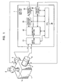
- the force-applying input device of the embodiment primarily comprises a mechanical section 1, an operation section 2, first and second actuators 3 and 4, first and second position sensors 5 and 6, and a control section 7.
- the mechanical section 1 comprises a tilting lever 1a.
- the operation section 2 is mounted to an end of the tilting lever 1a.
- the first and second actuators 3 and 4 apply a force to the operation section 2 through the tilting lever 1a.
- the first and second position sensors 5 and 6 detect the amount and direction of operation of the tilting lever 1a.
- the control section 7 generates drive signals e and f of the respective first and second actuators 3 and 4 by receiving first and second position signals a and b output from the respective first and second position sensors 5 and 6.
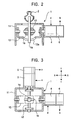
- the mechanical section 1 comprises the tilting lever 1a, a case 11, a lever holding shaft 12 (X shaft) rotatably held at the case 11, and a swing arm 13 (Y shaft).
- the lever holding shaft 12 and the swing arm 13 are disposed perpendicular to each other.
- the tilting lever 1a is mounted to the lever holding shaft 12 so as to be rotatable only in directions of rotation of the swing arm 13.
- reference numeral 1b denotes a central shaft for tilting the tilting lever 1a.
- the swing arm 13 has a long groove 13a through which the lower end portion of the tilting lever 1a passes.
- the width of the long groove 13a is slightly larger than the diameter of the lower end portion of the tilting lever 1a.
- the tilting lever 1a can be arbitrarily tilted in a direction with the lever holding shaft 12 and the central shaft 1b serving as centers.
- the lever holding shaft 12 is rotated in the tilting direction of the tilting lever 1a by an amount that is proportional to the tilting amount of the tilting lever 1a in a direction along the line X-X.
- the swing arm 13 is rotated in the tilting direction of the tilting lever 1a by an amount that is proportional to the tilting amount of the tilting lever 1a in a direction along the line Y-Y.
- the operation section 2 is formed with a shape and a size that allow an operator to operate the operation section 2.
- the first actuator 3 is connected to the lever holding shaft 12, and the second actuator 4 is connected to the swing arm 13.
- the first actuator 3 and the second actuator 4 may be electric devices, such as motors or solenoids.
- direct operated devices such as linear motors or solenoids
- a predetermined power transmission device for converting the rotational motion of the lever holding shaft 12 or the swing arm 13 into linear motion and transmitting the linear motion is disposed between the actuator 3 and the lever holding shaft 12 or between the actuator 4 and the swing arm 13.
- the first and second position sensors 5 and 6 detect the amount and direction of rotation of the rotary shafts of the first and second actuators 3 and 4, convert the detection results into electrical signals corresponding to the detection results, and output the electrical signals.
- the first and second position sensors 5 and 6 may be, for example, rotary encoders or rotary variable resistors.
- the rotary shaft of the first position sensor 5 is connected to the lever holding shaft 12, and the rotary shaft of the second position sensor 6 is connected to the swing arm 13.
- the control section 7 comprises an input section 21, a computing section 22, a storage section 23, driver circuits 24 and 25, and a central processing unit (CPU) 26.
- the input section 21 is used for inputting the first position signal output a from the first position sensor 5 and the second position signal b output from the second position sensor 6.
- the computing section 22 computes drive signals e and f of the first and second actuators 3 and 4 for applying a predetermined force to the operation section 2, based on the first and second position signals a and b.
- the storage section 23 stores, for example, predetermined operation amounts, and functions and coefficients serving as a basis for the computation.
- the driver circuits 24 and 25 drive the first and second actuators 3 and 4 by outputting drive powers c and d in accordance with the drive signals e and f output from the computing section 22.
- the CPU 26 controls each of these parts 21 to 25.
- the functions which are stored in the storage section 23 are linear functions in which the first and second position signals a and b are used as variables and the slopes are greater than 0, and exponential functions in which the first and second position signals a and b are used as variables and the exponents are greater than 1.
- the computing section 22 Based on the first and second position signals a and b input to the input section 21 and predetermined operation amounts, coefficients, and functions stored in the storage section 23, the computing section 22 carries out the following operations for determining force to be applied to the operation section 2:
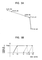
- the external force equal to the maximum value Fmax is applied in the point A direction.
- the direction of application of the external force changes successively in accordance with the amount of operation of the operation section 2, and the component of force in the direction opposite to the operation direction of the operation section 2 after changing the application direction increases gradually based on an exponential function stored in the storage section 23, and the component force in the direction opposite to the operation direction of the operation section 2 prior to changing the application direction is gradually reduced based on an exponential function stored in the storage section 23.
- the external force applied to the operation section 2 is reduced with an increase in the returning amount from a stopping position of the operation section 2.
- the returning amount of the operation section 2 reaches the predetermined returning amount corresponding to the predetermined operation amount, the application of the external force to the operation section 2 is stopped.
- oscillation of the operation section 2 is prevented from occurring, so that the operation section 2 can be stably held at the position where it is situated after the operation. Therefore, it is possible for an operator to experience an operational feel like that experienced when frictional force acts upon the operation section 2.
- the resultant of the external force component applied in the direction opposite to the operation direction of the operation section 2 prior to changing the operation direction and the external force component applied in the direction opposite to the operation direction of the operation section 2 after changing the operation direction is set equal to the maximum value Fmax. Therefore, the external force can be maintained at a constant value before and after changing the operation direction. Consequently, it is possible for the operator to experience an operational feel like that experienced when frictional force acts upon the operation section 2.
- the external force component applied in the direction opposite to the operation direction of the operation section 2 prior to changing the operation direction is gradually reduced and the external force component applied in the direction opposite to the operation direction of the operation section 2 after changing the operation direction is gradually increased. Therefore, it is possible to smoothly change the direction of application of the external force from the direction opposite to the operation direction of the operation section 2 prior to changing the operation direction to the direction opposite to the operation direction of the operation section 2 after changing the operation direction. Therefore, it is possible for the operator to experience an operational feel like that experienced when frictional force acts upon the operation section 2.
- the increase in the external force until the amount of operation of the operation section 2 reaches the predetermined operation amount from the start position A, and the reduction in the external force until the returning amount of the operation section reaches the predetermined returning amount from the stopping position are computed in accordance with linear functions having slopes greater than 0; and although the direction of application of the external force is computed in accordance with exponential functions having exponents greater than 1 when the operation direction of the operation section 2 is changed, the scope of the present invention is not limited thereto but to the scope of the appended claims. Therefore, they can be computed in accordance with any other functions.
Claims (3)
- Procédé pour commander un dispositif d'entrée d'application de force, comprenant :une section d'actionnement à palonnier ou joystick (2) ;un capteur de position (5, 6) pour détecter un état d'actionnement de la section d'actionnement ;un actionneur (3, 4) pour appliquer une force extérieure à la section d'actionnement (2) ; etune section de commande (7) pour commander l'actionnement de l'actionneur (3, 4) en fonction d'un signal de position délivré en sortie du capteur de position (5, 6), la section de commande (7) calculant des ampleurs d'actionnement et des directions d'actionnement de la section d'actionnement en fonction du signal de position, et commandant l'actionnement de l'actionneur, dans lequel,lorsque la section d'actionnement est actionnée dans une direction à partir d'une position de départ, une force extérieure qui augmente avec une augmentation de l'ampleur d'actionnement est appliquée dans une direction opposée à la direction d'actionnement de la section d'actionnement (2) jusqu'à ce que l'ampleur d'actionnement de la section d'actionnement atteigne une ampleur d'actionnement prédéterminée,lorsque l'ampleur d'actionnement de la section d'actionnement (2) atteint l'ampleur d'actionnement prédéterminée, la force extérieure correspondant à celle lorsque l'ampleur d'actionnement prédéterminée est atteinte est appliquée dans la direction opposée à la direction d'actionnement de la section d'actionnement ,caractérisé en ce que:lorsque la section d'actionnement (2) est arrêtée, La force extérieure appliquée à la section d'actionnement (2) est réduite avec une augmentation d'une ampleur de retour de la section d'actionnement à partir d'une position d'arrêt de la section d'actionnement (2),lorsque l'ampleur de retour de la section d'actionnement (2) atteint une ampleur de retour prédéterminée égale à l'ampleur d'actionnement prédéterminée, l'application de la force extérieure à la section d'actionnement est arrêtée, etlorsque la direction d'actionnement de la section d'actionnement (2) est changée durant l'actionnement de la section d'actionnement, une direction d'application de la force extérieure dans laquelle une résultante d'une première composante appliquée dans la direction opposée à la direction d'actionnement de la section d'actionnement avant le changement de la direction d'actionnement et d'une deuxième composante appliquée dans une direction opposée à la direction d'actionnement de la section d'actionnement après le changement de la direction d'actionnement est égale à la force extérieure correspondant à celle appliquée à la section d'actionnement lorsque l'ampleur d'actionnement prédéterminée est atteinte est calculée de façon répétée afin d'appliquer la force extérieure égale à la résultante dans la direction d'application de force extérieure calculée, la première composante étant graduellement réduite et la deuxième composante étant graduellement accrue avec une augmentation de l'ampleur d'actionnement de la section d'actionnement après le changement de la direction d'actionnement .
- Procédé selon la revendication 1, dans lequel, lorsque la section d'actionnement est actionnée dans une direction à partir de la position de départ, l'augmentation de la force extérieure jusqu'à ce que l'ampleur d'actionnement de la section d'actionnement atteigne l'ampleur d'actionnement prédéterminée à partir de la position de départ et la réduction de la force extérieure jusqu'à ce que l'ampleur de retour de la section d'actionnement (2) atteigne l'ampleur de retour prédéterminée à partir de la position d'arrêt sont calculées selon des fonctions linéaires ayant des pentes supérieures à 0.
- Procédé selon la revendication 1 ou 2, dans lequel, lorsque la direction d'actionnement de la section d'actionnement (2) est changée durant l'actionnement de la section d'actionnement (2), la direction d'application de la force extérieure est calculée selon une fonction exponentielle ayant un exposant supérieur à 1.
Applications Claiming Priority (2)
| Application Number | Priority Date | Filing Date | Title |
|---|---|---|---|
| JP2003046286A JP4160843B2 (ja) | 2003-02-24 | 2003-02-24 | 力覚付与型入力装置 |
| JP2003046286 | 2003-02-24 |
Publications (3)
| Publication Number | Publication Date |
|---|---|
| EP1450231A2 EP1450231A2 (fr) | 2004-08-25 |
| EP1450231A3 EP1450231A3 (fr) | 2006-05-10 |
| EP1450231B1 true EP1450231B1 (fr) | 2008-05-21 |
Family
ID=32733027
Family Applications (1)
| Application Number | Title | Priority Date | Filing Date |
|---|---|---|---|
| EP04003500A Expired - Fee Related EP1450231B1 (fr) | 2003-02-24 | 2004-02-17 | Dispositif d'entrée comprennant un dispositif pour appliquer une force |
Country Status (4)
| Country | Link |
|---|---|
| US (1) | US7245289B2 (fr) |
| EP (1) | EP1450231B1 (fr) |
| JP (1) | JP4160843B2 (fr) |
| DE (1) | DE602004013856D1 (fr) |
Families Citing this family (11)
| Publication number | Priority date | Publication date | Assignee | Title |
|---|---|---|---|---|
| JP4209235B2 (ja) * | 2003-03-28 | 2009-01-14 | アルプス電気株式会社 | 力覚付与型入力装置 |
| DE202005015434U1 (de) | 2005-09-30 | 2007-02-08 | Liebherr-Aerospace Lindenberg Gmbh | Steuervorrichtung für ein Luftfahrzeug |
| JP4760624B2 (ja) * | 2006-09-05 | 2011-08-31 | 株式会社デンソー | ポインタ操作装置およびポインタ操作装置に力を及ぼすためのプログラム |
| EP2068225B1 (fr) | 2007-12-05 | 2016-03-16 | Liebherr-Aerospace Lindenberg GmbH | Dispositif de commande |
| US8096206B2 (en) | 2007-12-05 | 2012-01-17 | Liebherr-Aerospace Lindenberg Gmbh | Control device |
| FR2934065B1 (fr) * | 2008-07-17 | 2010-08-27 | Airbus France | Dispositif pour la determination de la position d'une manette des gaz dans un aeronef |
| JP5241789B2 (ja) * | 2010-09-02 | 2013-07-17 | 株式会社ソニー・コンピュータエンタテインメント | プログラム、オブジェクト制御方法およびゲーム装置 |
| JP6201824B2 (ja) | 2014-03-05 | 2017-09-27 | 株式会社デンソー | 操作装置 |
| US10915136B2 (en) * | 2019-05-07 | 2021-02-09 | Sensata Technologies, Inc. | Dual mode sensing joystick assembly |
| KR102510904B1 (ko) * | 2019-07-31 | 2023-03-16 | 나부테스코 가부시키가이샤 | 조작 장치 및 선박용 조종 장치 |
| US11235885B2 (en) * | 2019-12-20 | 2022-02-01 | Pratt & Whitney Canada Corp. | Method and system for determining a throttle position of an aircraft |
Citations (1)
| Publication number | Priority date | Publication date | Assignee | Title |
|---|---|---|---|---|
| EP1411405A2 (fr) * | 2002-09-30 | 2004-04-21 | Alps Electric Co., Ltd. | Dispositif d'application de force |
Family Cites Families (20)
| Publication number | Priority date | Publication date | Assignee | Title |
|---|---|---|---|---|
| US4294162A (en) * | 1979-07-23 | 1981-10-13 | United Technologies Corporation | Force feel actuator fault detection with directional threshold |
| SE442852B (sv) * | 1983-04-18 | 1986-02-03 | Saab Scania Ab | Forfarande och anordning vid styrsystem for att astadkomma forhojd momentgradient for sma manoverdonsrorelser |
| FR2643502B1 (fr) * | 1989-02-20 | 1996-01-19 | Aerospatiale | Dispositif de commande a manche basculant, notamment pour aeronef, et systeme comportant un tel dispositif |
| US5691898A (en) * | 1995-09-27 | 1997-11-25 | Immersion Human Interface Corp. | Safe and low cost computer peripherals with force feedback for consumer applications |
| US6147674A (en) * | 1995-12-01 | 2000-11-14 | Immersion Corporation | Method and apparatus for designing force sensations in force feedback computer applications |
| US6050718A (en) * | 1996-03-28 | 2000-04-18 | Immersion Corporation | Method and apparatus for providing high bandwidth force feedback with improved actuator feel |
| US6411276B1 (en) * | 1996-11-13 | 2002-06-25 | Immersion Corporation | Hybrid control of haptic feedback for host computer and interface device |
| US6005551A (en) * | 1997-04-25 | 1999-12-21 | Microsoft Corporation | Offline force effect rendering |
| US6252579B1 (en) * | 1997-08-23 | 2001-06-26 | Immersion Corporation | Interface device and method for providing enhanced cursor control with force feedback |
| JP3850619B2 (ja) * | 1999-07-14 | 2006-11-29 | アルプス電気株式会社 | 車載用入力装置 |
| US6505088B1 (en) * | 2000-03-07 | 2003-01-07 | Mental Models, Inc. | Electronic controller |
| US6924787B2 (en) * | 2000-04-17 | 2005-08-02 | Immersion Corporation | Interface for controlling a graphical image |
| DE10029173A1 (de) * | 2000-06-19 | 2002-01-03 | Deutsch Zentr Luft & Raumfahrt | Verfahren und Anordnung zum Kommandieren von Steuerungsoperationen für kinematische Bewegungen eines Objekts unter Verwendung eines von Hand betätigbaren Eingabegerätes |
| US6539710B2 (en) * | 2001-02-09 | 2003-04-01 | Eaton Corporation | Hydrostatic steering system having improved steering sensing |
| US7024228B2 (en) * | 2001-04-12 | 2006-04-04 | Nokia Corporation | Movement and attitude controlled mobile station control |
| JP4125931B2 (ja) * | 2002-08-26 | 2008-07-30 | 株式会社ワコー | 回転操作量の入力装置およびこれを利用した操作装置 |
| JP4310127B2 (ja) * | 2003-04-14 | 2009-08-05 | アルプス電気株式会社 | 力覚付与型入力装置 |
| JP4220416B2 (ja) * | 2004-03-05 | 2009-02-04 | アルプス電気株式会社 | 力覚付与型入力装置 |
| JP2005332039A (ja) * | 2004-05-18 | 2005-12-02 | Alps Electric Co Ltd | 力覚付与型入力装置 |
| JP4264029B2 (ja) * | 2004-05-21 | 2009-05-13 | アルプス電気株式会社 | 力覚付与型入力装置 |
-
2003
- 2003-02-24 JP JP2003046286A patent/JP4160843B2/ja not_active Expired - Fee Related
-
2004
- 2004-02-17 DE DE602004013856T patent/DE602004013856D1/de not_active Expired - Fee Related
- 2004-02-17 EP EP04003500A patent/EP1450231B1/fr not_active Expired - Fee Related
- 2004-02-18 US US10/780,986 patent/US7245289B2/en not_active Expired - Fee Related
Patent Citations (1)
| Publication number | Priority date | Publication date | Assignee | Title |
|---|---|---|---|---|
| EP1411405A2 (fr) * | 2002-09-30 | 2004-04-21 | Alps Electric Co., Ltd. | Dispositif d'application de force |
Also Published As
| Publication number | Publication date |
|---|---|
| JP4160843B2 (ja) | 2008-10-08 |
| DE602004013856D1 (de) | 2008-07-03 |
| EP1450231A3 (fr) | 2006-05-10 |
| EP1450231A2 (fr) | 2004-08-25 |
| US20040167642A1 (en) | 2004-08-26 |
| JP2004258782A (ja) | 2004-09-16 |
| US7245289B2 (en) | 2007-07-17 |
Similar Documents
| Publication | Publication Date | Title |
|---|---|---|
| EP1450231B1 (fr) | Dispositif d'entrée comprennant un dispositif pour appliquer une force | |
| US6838851B2 (en) | Inner-force providing input device having a power-operated actuator for generating a click feel | |
| JP4220355B2 (ja) | 力覚付与型入力装置 | |
| JP2005332039A (ja) | 力覚付与型入力装置 | |
| JP2006263832A (ja) | ロボットの制御装置 | |
| JP5487822B2 (ja) | 力覚提示型ジョイスティックおよび全方向移動対象物の操作制御方法 | |
| US6922035B2 (en) | Force-applying input device | |
| JP2005332156A (ja) | 力覚付与型入力装置 | |
| US6859003B2 (en) | Force sense imparting/inputting apparatus capable of preventing oscillation of operation member, and imparting force sense | |
| JP5164853B2 (ja) | 自動車用途に対するギアチェンジ装置 | |
| US6943513B2 (en) | Force-applying input device | |
| JP2009258904A (ja) | 多方向入力装置 | |
| JP7216708B2 (ja) | 産業機械のために制御装置 | |
| JP2008095407A (ja) | ドア開閉アシスト装置 | |
| JP5410367B2 (ja) | 力覚付与型入力装置及び力覚付与型入力装置における自動中立復帰方法 | |
| JP2751383B2 (ja) | 操作具の操作感の制御装置 | |
| JP2008308923A (ja) | ドア開閉アシスト装置 | |
| EP1426853A2 (fr) | Dispositif d'entrée de données avec réaction de force | |
| JP2008038489A (ja) | ドア開閉アシスト装置 | |
| TW202326366A (zh) | 被操作裝置以及操作用裝置 | |
| JPH05331873A (ja) | 遠隔操作装置 | |
| JP2008223240A (ja) | ドア開閉アシスト装置 | |
| JP2003045288A (ja) | 多方向入力装置 |
Legal Events
| Date | Code | Title | Description |
|---|---|---|---|
| PUAI | Public reference made under article 153(3) epc to a published international application that has entered the european phase |
Free format text: ORIGINAL CODE: 0009012 |
|
| AK | Designated contracting states |
Kind code of ref document: A2 Designated state(s): AT BE BG CH CY CZ DE DK EE ES FI FR GB GR HU IE IT LI LU MC NL PT RO SE SI SK TR |
|
| AX | Request for extension of the european patent |
Extension state: AL LT LV MK |
|
| PUAL | Search report despatched |
Free format text: ORIGINAL CODE: 0009013 |
|
| AK | Designated contracting states |
Kind code of ref document: A3 Designated state(s): AT BE BG CH CY CZ DE DK EE ES FI FR GB GR HU IE IT LI LU MC NL PT RO SE SI SK TR |
|
| AX | Request for extension of the european patent |
Extension state: AL LT LV MK |
|
| RIC1 | Information provided on ipc code assigned before grant |
Ipc: G06F 3/00 20060101ALI20060320BHEP Ipc: G05G 9/047 20060101AFI20040422BHEP |
|
| 17P | Request for examination filed |
Effective date: 20060427 |
|
| 17Q | First examination report despatched |
Effective date: 20060703 |
|
| AKX | Designation fees paid |
Designated state(s): DE FR GB |
|
| GRAP | Despatch of communication of intention to grant a patent |
Free format text: ORIGINAL CODE: EPIDOSNIGR1 |
|
| GRAS | Grant fee paid |
Free format text: ORIGINAL CODE: EPIDOSNIGR3 |
|
| GRAA | (expected) grant |
Free format text: ORIGINAL CODE: 0009210 |
|
| AK | Designated contracting states |
Kind code of ref document: B1 Designated state(s): DE FR GB |
|
| REG | Reference to a national code |
Ref country code: GB Ref legal event code: FG4D |
|
| REF | Corresponds to: |
Ref document number: 602004013856 Country of ref document: DE Date of ref document: 20080703 Kind code of ref document: P |
|
| PLBE | No opposition filed within time limit |
Free format text: ORIGINAL CODE: 0009261 |
|
| STAA | Information on the status of an ep patent application or granted ep patent |
Free format text: STATUS: NO OPPOSITION FILED WITHIN TIME LIMIT |
|
| 26N | No opposition filed |
Effective date: 20090224 |
|
| PGFP | Annual fee paid to national office [announced via postgrant information from national office to epo] |
Ref country code: GB Payment date: 20090223 Year of fee payment: 6 |
|
| PGFP | Annual fee paid to national office [announced via postgrant information from national office to epo] |
Ref country code: DE Payment date: 20090428 Year of fee payment: 6 |
|
| REG | Reference to a national code |
Ref country code: FR Ref legal event code: ST Effective date: 20091030 |
|
| PG25 | Lapsed in a contracting state [announced via postgrant information from national office to epo] |
Ref country code: FR Free format text: LAPSE BECAUSE OF NON-PAYMENT OF DUE FEES Effective date: 20090302 |
|
| GBPC | Gb: european patent ceased through non-payment of renewal fee |
Effective date: 20100217 |
|
| PG25 | Lapsed in a contracting state [announced via postgrant information from national office to epo] |
Ref country code: DE Free format text: LAPSE BECAUSE OF NON-PAYMENT OF DUE FEES Effective date: 20100901 |
|
| PG25 | Lapsed in a contracting state [announced via postgrant information from national office to epo] |
Ref country code: GB Free format text: LAPSE BECAUSE OF NON-PAYMENT OF DUE FEES Effective date: 20100217 |