EP1449710A2 - Seat device including a stowable auxiliary seat - Google Patents
Seat device including a stowable auxiliary seat Download PDFInfo
- Publication number
- EP1449710A2 EP1449710A2 EP04002797A EP04002797A EP1449710A2 EP 1449710 A2 EP1449710 A2 EP 1449710A2 EP 04002797 A EP04002797 A EP 04002797A EP 04002797 A EP04002797 A EP 04002797A EP 1449710 A2 EP1449710 A2 EP 1449710A2
- Authority
- EP
- European Patent Office
- Prior art keywords
- seat
- supplementary
- vehicle
- cushion
- supplementary seat
- Prior art date
- Legal status (The legal status is an assumption and is not a legal conclusion. Google has not performed a legal analysis and makes no representation as to the accuracy of the status listed.)
- Granted
Links
Images


Classifications
-
- B—PERFORMING OPERATIONS; TRANSPORTING
- B60—VEHICLES IN GENERAL
- B60N—SEATS SPECIALLY ADAPTED FOR VEHICLES; VEHICLE PASSENGER ACCOMMODATION NOT OTHERWISE PROVIDED FOR
- B60N2/00—Seats specially adapted for vehicles; Arrangement or mounting of seats in vehicles
- B60N2/24—Seats specially adapted for vehicles; Arrangement or mounting of seats in vehicles for particular purposes or particular vehicles
- B60N2/30—Non-dismountable or dismountable seats storable in a non-use position, e.g. foldable spare seats
- B60N2/3002—Non-dismountable or dismountable seats storable in a non-use position, e.g. foldable spare seats back-rest movements
- B60N2/3029—Non-dismountable or dismountable seats storable in a non-use position, e.g. foldable spare seats back-rest movements by composed movement
-
- B—PERFORMING OPERATIONS; TRANSPORTING
- B60—VEHICLES IN GENERAL
- B60N—SEATS SPECIALLY ADAPTED FOR VEHICLES; VEHICLE PASSENGER ACCOMMODATION NOT OTHERWISE PROVIDED FOR
- B60N2/00—Seats specially adapted for vehicles; Arrangement or mounting of seats in vehicles
- B60N2/005—Arrangement or mounting of seats in vehicles, e.g. dismountable auxiliary seats
- B60N2/01—Arrangement of seats relative to one another
-
- B—PERFORMING OPERATIONS; TRANSPORTING
- B60—VEHICLES IN GENERAL
- B60N—SEATS SPECIALLY ADAPTED FOR VEHICLES; VEHICLE PASSENGER ACCOMMODATION NOT OTHERWISE PROVIDED FOR
- B60N2/00—Seats specially adapted for vehicles; Arrangement or mounting of seats in vehicles
- B60N2/24—Seats specially adapted for vehicles; Arrangement or mounting of seats in vehicles for particular purposes or particular vehicles
- B60N2/30—Non-dismountable or dismountable seats storable in a non-use position, e.g. foldable spare seats
- B60N2/3002—Non-dismountable or dismountable seats storable in a non-use position, e.g. foldable spare seats back-rest movements
- B60N2/3004—Non-dismountable or dismountable seats storable in a non-use position, e.g. foldable spare seats back-rest movements by rotation only
- B60N2/3009—Non-dismountable or dismountable seats storable in a non-use position, e.g. foldable spare seats back-rest movements by rotation only about transversal axis
-
- B—PERFORMING OPERATIONS; TRANSPORTING
- B60—VEHICLES IN GENERAL
- B60N—SEATS SPECIALLY ADAPTED FOR VEHICLES; VEHICLE PASSENGER ACCOMMODATION NOT OTHERWISE PROVIDED FOR
- B60N2/00—Seats specially adapted for vehicles; Arrangement or mounting of seats in vehicles
- B60N2/24—Seats specially adapted for vehicles; Arrangement or mounting of seats in vehicles for particular purposes or particular vehicles
- B60N2/30—Non-dismountable or dismountable seats storable in a non-use position, e.g. foldable spare seats
- B60N2/3002—Non-dismountable or dismountable seats storable in a non-use position, e.g. foldable spare seats back-rest movements
- B60N2/3004—Non-dismountable or dismountable seats storable in a non-use position, e.g. foldable spare seats back-rest movements by rotation only
- B60N2/3018—Non-dismountable or dismountable seats storable in a non-use position, e.g. foldable spare seats back-rest movements by rotation only about vertical axis
-
- B—PERFORMING OPERATIONS; TRANSPORTING
- B60—VEHICLES IN GENERAL
- B60N—SEATS SPECIALLY ADAPTED FOR VEHICLES; VEHICLE PASSENGER ACCOMMODATION NOT OTHERWISE PROVIDED FOR
- B60N2/00—Seats specially adapted for vehicles; Arrangement or mounting of seats in vehicles
- B60N2/24—Seats specially adapted for vehicles; Arrangement or mounting of seats in vehicles for particular purposes or particular vehicles
- B60N2/30—Non-dismountable or dismountable seats storable in a non-use position, e.g. foldable spare seats
- B60N2/3038—Cushion movements
- B60N2/304—Cushion movements by rotation only
- B60N2/3043—Cushion movements by rotation only about longitudinal axis
-
- B—PERFORMING OPERATIONS; TRANSPORTING
- B60—VEHICLES IN GENERAL
- B60N—SEATS SPECIALLY ADAPTED FOR VEHICLES; VEHICLE PASSENGER ACCOMMODATION NOT OTHERWISE PROVIDED FOR
- B60N2/00—Seats specially adapted for vehicles; Arrangement or mounting of seats in vehicles
- B60N2/24—Seats specially adapted for vehicles; Arrangement or mounting of seats in vehicles for particular purposes or particular vehicles
- B60N2/30—Non-dismountable or dismountable seats storable in a non-use position, e.g. foldable spare seats
- B60N2/3081—Seats convertible into parts of the seat cushion or the back-rest or disapppearing therein, e.g. for children
- B60N2/3086—Disappearing in a recess of the cushion
-
- B—PERFORMING OPERATIONS; TRANSPORTING
- B60—VEHICLES IN GENERAL
- B60N—SEATS SPECIALLY ADAPTED FOR VEHICLES; VEHICLE PASSENGER ACCOMMODATION NOT OTHERWISE PROVIDED FOR
- B60N2/00—Seats specially adapted for vehicles; Arrangement or mounting of seats in vehicles
- B60N2/75—Arm-rests
- B60N2/753—Arm-rests movable to an inoperative position
- B60N2/757—Arm-rests movable to an inoperative position in a recess of the back-rest
-
- B—PERFORMING OPERATIONS; TRANSPORTING
- B60—VEHICLES IN GENERAL
- B60N—SEATS SPECIALLY ADAPTED FOR VEHICLES; VEHICLE PASSENGER ACCOMMODATION NOT OTHERWISE PROVIDED FOR
- B60N2/00—Seats specially adapted for vehicles; Arrangement or mounting of seats in vehicles
- B60N2/75—Arm-rests
- B60N2/79—Adaptations for additional use of the arm-rests
-
- B—PERFORMING OPERATIONS; TRANSPORTING
- B60—VEHICLES IN GENERAL
- B60N—SEATS SPECIALLY ADAPTED FOR VEHICLES; VEHICLE PASSENGER ACCOMMODATION NOT OTHERWISE PROVIDED FOR
- B60N2/00—Seats specially adapted for vehicles; Arrangement or mounting of seats in vehicles
- B60N2/80—Head-rests
- B60N2/806—Head-rests movable or adjustable
- B60N2/809—Head-rests movable or adjustable vertically slidable
- B60N2/832—Head-rests movable or adjustable vertically slidable movable to an inoperative or stowed position
- B60N2/835—Head-rests movable or adjustable vertically slidable movable to an inoperative or stowed position specially adapted for rear seats
-
- B—PERFORMING OPERATIONS; TRANSPORTING
- B60—VEHICLES IN GENERAL
- B60N—SEATS SPECIALLY ADAPTED FOR VEHICLES; VEHICLE PASSENGER ACCOMMODATION NOT OTHERWISE PROVIDED FOR
- B60N2/00—Seats specially adapted for vehicles; Arrangement or mounting of seats in vehicles
- B60N2/80—Head-rests
- B60N2/891—Head-rests with the head-rest being comma-shaped in side view
Landscapes
- Engineering & Computer Science (AREA)
- Aviation & Aerospace Engineering (AREA)
- Transportation (AREA)
- Mechanical Engineering (AREA)
- Seats For Vehicles (AREA)
Abstract
Description
- The present invention relates to a seat device for a vehicle, and more particularly to a seat device which is equipped with a supplementary seat at a side of a vehicle seat.
- Conventionally, a supplementary seat, which is configured so as to be stored in somewhere in a vehicle compartment, is used for the purpose of compatibility of providing a roomy space for few passengers and an enough sitting space for crowded passengers.
- For example, Japanese Patent Laid-Open Publication No. 2002-225603 discloses a seat device comprising a seat which includes a seat cushion and a seat back and a supplementary seat which is disposed at a side of the seat and includes a supplementary seat cushion and a supplementary seat back, in which the seat cushion includes a storage box with an upward opening and a cushion covering the opening. Herein, this seat device is configured such that in the event that the supplementary seat is not used, the cushion of the seat cushion is rotated forward to open the storage box and the supplementary seat back is folded on the supplementary seat cushion, and then the folded supplementary seat is swung toward the storage box and stored in it.
- Herein, the above-described prior art has the following problem.
- Namely, the seat back and the seat cushion of the supplementary seat are integral with each other. Therefore, a whole of the supplementary seat along with the seat back and the seat cushion thereof needs to be stored in the storage box.
- Accordingly, since a depth of the storage box needs to be enough deep to store the whole supplementary seat, this device may require a high sitting point of the seat and thereby may deteriorate a comfortable ride.
- Accordingly, it is an object of the present invention to provide a seat device for a vehicle with a supplementary seat, which provides a better operability.
- This object is solved according to the invention by a seat device according to
claim 1. Preferred embodiments of the invention are subject of the dependent claims. - Accordingly, the inventive seat device enables a storage of the supplementary seat without deteriorating a comfortable ride of a seat storing the supplementary seat in it and can provide any other usage of the supplementary seat thus improving overall operability.
- According to the present invention, there is provided a seat device for a vehicle, comprising:
- at least one seat including a seat cushion, a seat back and a storage recess;
- a supplementary seat disposed at a side of said seat,
- said supplementary seat comprises
a supplementary seat back which is pivotally supported so as to allow the supplementary seat back to rotate in a longitudinal direction of the vehicle, and
a supplementary seat cushion which is formed separately from the supplementary seat back, and - said supplementary seat cushion of the supplementary seat is configured so as to selectively take a sitting position, where the supplementary seat cushion is located substantially at the side of the seat cushion of said seat, and a stored position, where the supplementary seat cushion is stored in the storage recess of said seat.
-
- According to the present invention, since the supplementary seat cushion and the supplementary seat back are formed separately from each other and only the supplementary seat cushion is stored in the storage recess, the depth (height) of the storage recess can be decreased as much as possible. As a result, this can suppress the deterioration of comfortable ride caused by the high-sitting point arrangement of the seat storing the supplementary seat and improve overall operability of the seat device.
- According to a preferred embodiment of the invention, said seat cushion of the seat comprises a cushion body portion that includes a storage recess with an upward opening and a cushion bottom portion that covers the opening of the storage recess so as to selectively open or close the opening.
- Preferably, the supplementary seat back has its upper end portion detachably supported on a side portion of said seat and its lower end portion pivotally supported on the side portion of said seat so as to allow the supplementary seat back to rotate in a longitudinal direction of the vehicle.
- Most preferably, the supplementary seat cushion can be disposed below the supplementary seat back and at a side of said seat cushion of the seat.
- According to a further preferred embodiment of the present invention, there is provided a seat device for a vehicle, comprising a seat including a seat cushion and a seat back, and a supplementary seat disposed at a side of the seat, wherein the seat cushion of the seat comprises a cushion body portion that includes a storage recess with an upward opening and a cushion bottom portion that covers the opening of the storage recess so as to selectively open or close the opening, the supplementary seat comprises a supplementary seat back, of which an upper end portion is detachably supported on a side portion of the seat and a lower end portion is pivotally supported on the side portion of the seat so as to allow the supplementary seat back to rotate in a longitudinal direction of the vehicle, and a supplementary seat cushion which is formed separately from the supplementary seat back and disposed below the supplementary seat back and at a side of the seat cushion of the seat, and the supplementary seat cushion of the supplementary seat is configured so as to selectively take a sitting position, where the supplementary seat cushion is located at the side of the seat cushion of the seat, and a stored position, where the supplementary seat cushion is stored in the storage recess of the seat cushion body portion of the seat.
- Accordingly, since the supplementary seat back is configured such that its upper end portion is detachably supported and its lower end portion is pivotally supported so as to allow the supplementary seat back to rotate in the longitudinal direction of the vehicle, it can be rotated forward to provide its substantially horizontal position which functions as a table or an armrest. As a result, this can improve utility of the seat device without providing additional members.
- According to a preferred embodiment of the invention, the seat cushion of the seat includes a swing mechanism for pivoting the supplementary seat cushion of the supplementary seat so as to allow the supplementary seat cushion to swing substantially in a width direction of the vehicle.
- Accordingly, since the seat cushion includes the above-described swing mechanism, this seat device can store easily the supplementary seat cushion in the storage recess of the seat which is disposed at the side of the supplementary seat cushion.
- Preferably, the supplementary seat back of the supplementary seat includes a rotational mechanism for rotating the supplementary seat back from its sitting position to allow the supplementary seat back to take at least a first rotational position, where the supplementary seat back is rotated in a width direction of the vehicle and a back face of the supplementary seat back faces substantially toward the width direction of the vehicle, and a second rotational position, where the supplementary seat back is rotated forward from the first rotational position and a side face of the supplementary seat back faces substantially upward.
- Herein, in the event that the supplementary seat back is used as an armrest, just rotating the supplementary seat back forward may not provide an appropriate position of the supplementary seat back. Because, the back face of the rotated supplementary seat back, which now constitutes an upward-rest surface of the armrest, would be located at a relatively lower position in a vertical direction of the vehicle, and this lower position of the back face, i.e., upward-rest surface of the armrest, may not necessarily provide the best position of the armrest (supplementary seat back). (Because generally the supplementary seat back is configured in a shape that its width is longer that its thickness.)
- Accordingly, since the supplementary seat back includes the above-described rotational mechanism, the supplementary seat back is rotated in the width direction of the vehicle and then forward, in the event that it is not used as the seat. The side face of the supplementary seat back rotated in the above-described way is rotated accordingly so as to constitute an upward-rest surface of an armrest, and thereby this can provide a higher position of the armrest substantially. As a result, the supplementary seat back can be used as an armrest appropriately, thereby improving the utility of the seat device.
- Further preferably, the seat includes two seats disposed separately in a width direction of the vehicle, the supplementary seat is disposed between the two seats, and the supplementary seat back of the supplementary seat includes a rotational mechanism for rotating the supplementary seat back from its sitting position to allow the supplementary seat back to take at least a position where the supplementary seat back is rotated in a width direction of the vehicle and a back face of the supplementary seat back faces substantially toward the width direction of the vehicle.
- Accordingly, a simple operation that only the supplementary seat cushion of the supplementary seat disposed between the two seats is stored in the storage recess and the supplementary seat back is rotated in the width direction of the vehicle to be folded can provide a walk-through space disposed between the two seats easily.
- Still further preferably, the supplementary seat cushion and the supplementary seat back are respectively changed in their positions by the swing mechanism and the rotational mechanism such that the seat device provides at least one of the following uses:
- a use mode where the supplementary seat functions as a seat,
- a walk-through or open mode where the supplementary seat cushion is stored in the storage recess and the supplementary seat back takes the first rotational position, and
- an armrest mode where at least the supplementary seat back takes the second rotational position.
-
- Accordingly, the seat device providing the above-described selectively up to three modes can be easily obtained thus improving overall operability.
- Most preferably, the supplementary seat comprises a support member for selectively supporting the supplementary seat on a car body portion, preferably on a floor portion thereof.
- Accordingly, the supplementary seat is effectively supported on the car body, e.g. when taking the use mode where the supplementary seat functions as a seat and a person may be seated on the supplementary seat.
- Other features, aspects, and advantages of the present invention will be apparent from the following description of the present invention which refers to the accompanying drawings.
- FIG. 1 is a plan view of a vehicle for showing a seat arrangement according to a first embodiment of the present invention.
- FIG. 2 is a perspective view of a second-row seat according to the first embodiment, when viewed from the right side of the vehicle.
- FIG. 3 is a perspective view of the second-row seat according to the first embodiment in which a rear end of a cushion bottom portion is rotated upward, when viewed from the right side of the vehicle.
- FIG. 4 is a perspective view of the second-row seat according to the first embodiment in which a supplementary seat cushion is stored in a storage recess, when viewed from the right side of the vehicle.
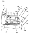
- FIG. 5 is a perspective view of the second-row seat according to the first embodiment in which a supplementary seat cushion is stored in a storage recess, when viewed from the left side of the vehicle.
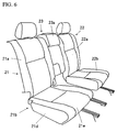
- FIG. 6 is a perspective view of the second-row seat according to the first embodiment in which the supplementary seat cushion is stored in a storage recess and the cushion bottom portion is returned to a sitting position, when viewed from the right side of the vehicle.
- FIG. 7 is an elevation view of the second-row seat according to the first embodiment in which the supplementary seat takes a walk-through mode, when viewed from the front side of the vehicle.
- FIG. 8 is a perspective view of the supplementary seat back according to the first embodiment in which the supplementary seat takes a walk-through mode, when viewed from the left side of the vehicle.
- FIG. 9 is a perspective view of the supplementary seat back according to the first embodiment in which the supplementary seat takes an armrest mode, when viewed from the left side of the vehicle.
- FIG. 10 is a perspective view of a supplementary seat back according to another embodiment of the present invention in which the supplementary seat back takes an armrest mode, when viewed from the left side of the vehicle.
-
- Hereinafter, a seat device for a vehicle according to a preferred embodiment of the present invention will be described with reference to the accompanying drawings.
- FIG. 1 is a plan view of a vehicle for showing a seat arrangement according to the first embodiment.
- In a
vehicle 1, there are provided a first-row seat 10 disposed at the front of the vehicle, a second-row seat 20 disposed behind the first-row seat 10, and a third-row seat 30 disposed behind the second-row seat 20. - The first-
row seat 10 is comprised of adriver seat 11 and apassenger seat 12. The second-row seat 20 is comprised of a right-sidesecond seat 21 disposed behind thedriver seat 11, a left-sidesecond seat 22 disposed behind thepassenger seat 12, and asupplementary seat 23 disposed between the bothsecond seats row seat 30 is comprised of a bench seat on which two or three of passengers can sit. - Next, the
second seat 20 including thesupplementary seat 23 will be described referring to FIG. 2. - FIG. 2 is a perspective view of the second-
row seat 20, when viewed from the right side of the vehicle. The right-sidesecond seat 21 and the left-sidesecond seat 22 are respectively comprised of theirseat backs seat cushions - Further, the
seat cushion 21b of the right-sidesecond seat 21 comprises acushion body portion 21d including astorage recess 21c (not shown in FIG. 2) with an upward opening and acushion bottom portion 21e at least partly covering the opening of thestorage recess 21c so as to selectively open or close the opening and enable a passenger to sit thereon. - Further, the
supplementary seat 23 is comprised of a supplementary seat back 23a and asupplementary seat cushion 23b which is formed separately from the supplementary seat back 23a. - The supplementary seat back 23a is configured such that its upper end portion is detachably supported on a side portion of an adjacent seat, in particular of the seat back 21a of the right-side
second seat 21 and its lower end portion is pivotally supported on a side portion of the right-sidesecond seat 21, which will be described more below. - Meanwhile, the
supplementary seat cushion 23b is configured so as to selectively take a sitting position, where it is located at the side of theseat cushion 21a of the adjacent or right-sidesecond seat 21, and a stored position, where it is stored in the above-describedstorage recess 21c, which will be described more below. - Next, storage of the
supplementary seat cushion 23b in thestorage recess 21c will be described referring to FIGS. 3 through 6. - FIG. 3 is a perspective view of the second-
row seat 20, in which a rear end of thecushion bottom portion 21e is rotated or pivoted upward, when viewed from the right side of thevehicle 1. FIG. 4 is a perspective view of the second-row seat 20, in which thesupplementary seat cushion 23b is substantially stored in thestorage recess 21c, when viewed from the right side of the vehicle. FIG. 5 is a perspective view of the second-row seat 20, in which thesupplementary seat cushion 23b is stored in thestorage recess 21c, when viewed from the left side of thevehicle 1. FIG. 6 is a perspective view of the second-row seat 20, in which thesupplementary seat cushion 23b is stored in thestorage recess 21c and thecushion bottom portion 21e is substantially returned towards or to a sitting position, when viewed from the right side of the vehicle. - With respect to the storage of the
supplementary seat cushion 23b in thestorage recess 21c, as shown in FIG. 3, at first thecushion bottom portion 21e is rotated or pivoted about one or more (e.g. two) supportingportions side supporting portion 21f shown in FIG. 3), which are attached at the front and preferably both sides of thecushion bottom portion 21e, with its rear end rising up, and thereby thestorage recess 21c substantially opens. - The
supplementary seat cushion 23b is attached to a side wall of acushion body portion 21d of theseat 21 having thestorage recess 21c through an attachingmember 24, which is swingable in the width direction of thevehicle 1 so as to enable thesupplementary seat cushion 23b to selectively take a sitting position, where thesupplementary seat cushion 23b is located at the side of theseat cushion 21b of the right-sidesecond seat 21 and thereby a passenger is able to sit on it, and a stored position, where thesupplementary seat cushion 23b is substantially stored in thestorage recess 21c. (The attachingmember 24 constitutes a preferred swing mechanism.) - Herein, a
reference numeral 23c denotes a foldable leg (as a preferred supporting means) disposed at a bottom face of thesupplementary seat cushion 23b. Theleg 23c is to be placed on a vehicle floor, shown in FIG. 3, to support a load of a sitting passenger in the event of use of thesupplementary seat 23. Meanwhile, it can be folded over the bottom face of thesupplementary seat cushion 23b in the event of non-use of thesupplementary seat 23. - Next, as shown in FIG. 4, the
supplementary seat cushion 23b is swung toward the right-sidesecond seat 21 from its position shown in FIG. 3 and substantially stored in thestorage recess 21c, and then theleg 23c is folded as shown in FIG. 5. - Then, as shown in FIG. 6, the
cushion bottom portion 21e is rotated or pivoted downward with its rear end going down from its position shown in FIG. 5, and thereby thestorage recess 21c is substantially closed. - As described above, when the
supplementary seat 23 is not used, thesupplementary seat cushion 23b can be substantially stored in thestorage recess 21c. - Next, a structure and an usage mode change of the supplementary seat back 23a will be described referring to FIGS. 7 through 9.
- FIG. 7 is an elevation view of the second-
row seat 20, when viewed from the front side of the vehicle, in which the supplementary seat back 23a is located among the first-row seat 10 through the third-row seat 30 to take an open or walk-through mode. FIG. 8 is a perspective view of the supplementary seat back 23a in which the supplementary seat back 23a is located among the first-row seat 10 through the third-row seat 30 to take an open or walk-through mode, when viewed from the left side of thevehicle 1. FIG. 9 is a perspective view of the supplementary seat back 23a in which the supplementary seat back 23a takes an armrest mode, when viewed from the left side of the vehicle. - The supplementary seat back 23a is comprised of a first seat back
portion 23d, which is pivotally supported on the adjacent seat, preferably on a lower-side portion of the seat back 21a of the right-sidesecond seat 21 through a rotational or pivotal axis C1 (being preferably arranged substantially along the lateral direction of the vehicle 1) shown in a broken line so as to rotate or pivot preferably substantially along the longitudinal direction of thevehicle 1, and a second seat backportion 23e and a third seat backportion 23f, which are located above the first seat backportion 23d and pivotally supported on an upper surface of the first seat backportion 23d through a rotational or pivotal axis C2 (arranged at an angle different from 0° or 180°, preferably substantially normal to the first rotational axis C1) shown in a broken line so as to rotate or pivot preferably substantially along the width direction of thevehicle 1. - Herein, the third seat back
portion 23f preferably functions as a headrest. - Next, the mode of the supplementary seat back 23a will be described.
- The supplementary seat back 23a is configured so as to change its mode among three modes, i.e., use mode, walk-trough or open mode and armrest mode.
- First, the use mode will be described.
- The use mode is a mode in which the supplementary seat back 23a is used as a seat back. In this case, the supplementary seat back 23a is, as shown in FIGS. 2 through 6, disposed between the seat back 21a of the right-side
second seat 21 preferably with substantially no space between them, and the seat back 22a of the left-sidesecond seat 22 functions as a seat back. Accordingly, the seat back 21a, the supplementary seat back 23a and the seat back 22a are substantially arranged on one plane and preferably form a substantially closed surface having substantially no open space (see FIG. 2). - Next, the walk-through or open mode will be described.
- The walk-through mode is a mode in which the second and third seat back
portions vehicle 1 and thereby a space for allowing passengers to walk through between the second-row seat and the third-row seat or at least to allow objects to be passed through (e.g. to allow ski to be passed between the twoseats 21 and 22) is at least partly formed between the seat back 21a of the right-sidesecond seat 21 and the seat back 22a of the left-sidesecond seat 22. As shown in FIGS. 7 and 8, the second and third seat backportions portions second seat 22 are located rearward, and side faces thereof at the side of the right-sidesecond seat 21 are located substantially forward. As a result, there is provided the space at least partly between the seat back 21a of the right-sidesecond seat 21 and the seat back 22a of the left-sidesecond seat 22, which enables passengers to walk through or to pass objects therethrough. - Finally, the armrest mode will be described.
- The armrest mode is a mode in which the supplementary seat back 23a is used as an armrest and/or to rest objects thereon when the
supplementary seat 23 is not used as a seat. The supplementary seat back 23a is rotated or pivoted forward around the rotational axis C1, i.e., in an arrow B direction of FIG. 9, from the position shown in FIG. 8 to the substantially horizontal position (second rotational position). As a result, the side face of the supplementary seat back 23a at the side of the left-sidesecond seat 22 is located so as to face substantially upward, and thus this side face can be used as a rest surface of the armrest and/or to rest objects thereon. - Herein, the armrest mode may be constituted, as shown in FIG. 10, by simply rotating the supplementary seat back 23a forward from its use-mode position, without by way of its walk-through-mode position. In this case, a back face of the supplementary seat back 23a is located to face substantially upward, and the back face will be used as the rest surface of the armrest.
- However, in this case shown in FIG. 10, the position of the face of the supplementary seat back 23a which is used as the rest surface of the armrest may be lower than that of the case shown in FIG. 9. (Because generally the supplementary seat back is configured in a shape that its width is longer that its thickness.)
- As described above, according to the present embodiment, since the
supplementary seat cushion 23b and the supplementary seat back 23a are formed separately from each other and only thesupplementary seat cushion 23b is stored in thestorage recess 21c, the depth (height) of thestorage recess 21c can be decreased as much as possible. As a result, this can suppress the deterioration of comfortable ride caused by the high-sitting point arrangement of the right-sidesecond seat 21 storing thesupplementary seat 23. - Further, since the supplementary seat back 23a is configured such that its upper end portion is detachably supported and its lower end portion is pivotally supported so as to allow the supplementary seat back 23a to rotate or pivot in or along the longitudinal direction of the
vehicle 1, it can be used as a table or an armrest. As a result, this can improve utility of the seat device without providing additional members. - Further, since the
seat cushion 21b includes the attachingmember 24 to support pivotally thesupplementary seat cushion 23b in the width direction of thevehicle 1, this seat device can store easily thesupplementary seat cushion 23b in thestorage recess 21c of the right-sidesecond seat 21. - Further, there is provided the rotational mechanism (pivot axes C1, C2) for rotating or pivoting the supplementary seat back 23a to allow it to take the first rotational position, where it is rotated or pivoted in the width direction of the vehicle 1 (around the axis C2) and its back face faces substantially toward the width direction of the
vehicle 1, and the second rotational position, where it is rotated or pivoted forward from the first rotational position and its side face faces substantially upward (around the axis C1). Accordingly, in the event that the supplementary seat back 23 is not used as the seat, the supplementary seat back 23a is rotated in the width direction of thevehicle 1 and then forward. Thereby, this can locate the side face of the supplementary seat back 23 a at a higher position. As a result, the supplementary seat back 23a can be used as an armrest appropriately, thereby improving the utility of the seat device. - Further, a simple operation that only the
supplementary seat cushion 23b is stored in thestorage recess 21c and the supplementary seat back 23a is rotatedor pivoted in the width direction of thevehicle 1 to be folded can provide the walk-through space or opening space disposed between the twosecond seats - Although the
supplementary seat 23 is disposed between the right-sidesecond seat 21 and the left-sidesecond seat 22 in the present embodiment, the third-row seat 30 may be composed of two or more separate seats instead of a bench type of seat and thesupplementary seat 23 may be disposed between them. - Further, the
supplementary seat 23 may be disposed beside either the right-sidesecond seat 21 or the left-sidesecond seat 22 and at a door's side, not being disposed between the seats like the present embodiment. - Also, although in the present embodiment the
supplementary seat cushion 23b of thesupplementary seat 23 is pivotally attached to the side portion of theseat cushion 21b of the right-sidesecond seat 21 so as to swing or pivot or rotate, it may be attached to a vehicle floor. - Accordingly, a
seat cushion 21 comprises acushion body portion 21d including astorage recess 21c and acushion bottom portion 21e substantially covering thestorage recess 21c so as to selectively open or close it. Asupplementary seat 23 comprises a supplementary seat back 23a which is pivotally supported so as to rotate in the longitudinal direction and asupplementary seat cushion 23b formed separately from the supplementary seat back 23a. Thesupplementary seat cushion 23b is configured so as to selectively take a sitting position, where it is located at the side of the seat cushion, and a stored position, where it is stored in thestorage recess 21c. - Accordingly, since only the
supplementary seat cushion 23b and not the supplementary seat back 23a is stored in thestorage recess 21c, the deterioration of comfortable ride caused by the high-sitting point can be suppressed. Also, the supplementary seat back 23a can be preferably used as a armrest or support portion or the like thus improving overall operability. - Any other additional modification may be applied within the scope of the present invention.
Claims (9)
- A seat device for a vehicle (1), comprising:at least one seat (21; 22) including a seat cushion (21b; 22b), a seat back (21a; 22a) and a storage recess (21c);a supplementary seat (23) disposed at a side of said seat (21; 22),said supplementary seat (23) comprises
a supplementary seat back (23a) which is pivotally supported so as to allow the supplementary seat back (23a) to rotate in a longitudinal direction (B) of the vehicle (1), and
a supplementary seat cushion (23b) which is formed separately from the supplementary seat back (23a), andsaid supplementary seat cushion (23b) of the supplementary seat (23) is configured so as to selectively take a sitting position, where the supplementary seat cushion (23b) is located substantially at the side of the seat cushion (21b; 22b) of said seat (21; 22), and a stored position, where the supplementary seat cushion (23b) is stored in the storage recess (21c) of said seat (21; 22). - The seat device for a vehicle of claim 1, wherein said seat cushion (21b; 22b) of the seat (21; 22) comprises a cushion body portion (21d) that includes a storage recess (21c) with an upward opening and a cushion bottom portion (21e) that covers the opening of the storage recess (21c) so as to selectively open or close the opening.
- The seat device for a vehicle of one of the preceding claims, wherein the supplementary seat back (23a) has its upper end portion detachably supported on a side portion of said seat (21; 22) and its lower end portion pivotally supported on the side portion of said seat (21; 22) so as to allow the supplementary seat back (23a) to rotate in a longitudinal direction (B) of the vehicle (1).
- The seat device for a vehicle of one of the preceding claims, wherein the supplementary seat cushion (23b) can be disposed below the supplementary seat back (23a) and at a side of said seat cushion (21b; 22b) of the seat (21; 22).
- The seat device for a vehicle of one of the preceding claims, wherein said seat cushion (21b; 22b) of the seat (21; 22) includes a swing mechanism (24) for pivoting said supplementary seat cushion (23b) of the supplementary seat (23) so as to allow the supplementary seat cushion (23b) to swing (A) substantially in a width direction of the vehicle (1).
- The seat device of a vehicle of one of the preceding claims, wherein said supplementary seat back (23a) of the supplementary seat (23) includes a rotational mechanism (C1, C2) for rotating the supplementary seat back (23a) from its sitting position to allow the supplementary seat back (23a) to take at least a first rotational position, where the supplementary seat back (23a) is rotated (A) in a width direction of the vehicle (1) and a back face of the supplementary seat back (23a) faces substantially toward the width direction of the vehicle (1), and a second rotational position, where the supplementary seat back (23a) is rotated (B) forward from the first rotational position and a side face of the supplementary seat back (23a) faces substantially upward.
- The seat device for a vehicle of one of the preceding claims, wherein said seat includes two seats (21, 22) disposed separately in a width direction of the vehicle (1), said supplementary seat (23) is disposed between the two seats (21, 22), and said supplementary seat back (23a) of the supplementary seat (23) includes a rotational mechanism (C2) for rotating the supplementary seat back (23a) from its sitting position to allow the supplementary seat back (23a) to take at least a position where the supplementary seat back (23a) is rotated (A) in a width direction of the vehicle (1) and a back face of the supplementary seat back (23a) faces substantially toward the width direction of the vehicle (1).
- The seat device for a vehicle of one of the preceding claims, wherein said supplementary seat cushion (23b) and said supplementary seat back (23a) are respectively changed in their positions by said swing mechanism (24) and said rotational mechanism (C1, C2) such that the seat device provides at least one of the following uses:a use mode where the supplementary seat (23) functions as a seat,a walk-through or open mode where the supplementary seat cushion (23b) is stored in said storage recess (21c) and the supplementary seat back (23a) takes said first rotational position, andan armrest mode where at least the supplementary seat back (23a) takes said second rotational position.
- The seat device for a vehicle of one of the preceding claims, wherein the supplementary seat (23) comprises a support member for selectively supporting the supplementary seat (23) on a car body portion, preferably on a floor portion thereof.
Applications Claiming Priority (2)
| Application Number | Priority Date | Filing Date | Title |
|---|---|---|---|
| JP2003040570A JP4135523B2 (en) | 2003-02-19 | 2003-02-19 | Vehicle seat device |
| JP2003040570 | 2003-02-19 |
Publications (3)
| Publication Number | Publication Date |
|---|---|
| EP1449710A2 true EP1449710A2 (en) | 2004-08-25 |
| EP1449710A3 EP1449710A3 (en) | 2007-05-23 |
| EP1449710B1 EP1449710B1 (en) | 2011-10-05 |
Family
ID=32732931
Family Applications (1)
| Application Number | Title | Priority Date | Filing Date |
|---|---|---|---|
| EP04002797A Expired - Fee Related EP1449710B1 (en) | 2003-02-19 | 2004-02-09 | Seat device including a stowable auxiliary seat |
Country Status (3)
| Country | Link |
|---|---|
| US (1) | US6811200B2 (en) |
| EP (1) | EP1449710B1 (en) |
| JP (1) | JP4135523B2 (en) |
Cited By (9)
| Publication number | Priority date | Publication date | Assignee | Title |
|---|---|---|---|---|
| EP1493624A1 (en) * | 2003-07-02 | 2005-01-05 | Mazda Motor Corporation | Combination structure of storage box and center seat for vehicle |
| DE102007053958A1 (en) | 2007-02-26 | 2008-08-28 | Johnson Controls Gmbh | Vehicle seating has seat segment with seat part and another seat segment with another seat part and backrest and latter seat segment is stowed under seat part |
| DE102007055081A1 (en) | 2007-07-05 | 2009-01-08 | Johnson Controls Gmbh | Vehicle seat with securing means for a support element |
| DE102007055144A1 (en) | 2007-11-19 | 2009-05-20 | Ford-Werke Gmbh | Seat i.e. middle seat, for use in seat arrangement in vehicle, has back part longitudinally-changeable between one final position at which back part exhibits greater length formed as seat length and another final position |
| DE102008029261A1 (en) * | 2008-06-19 | 2009-12-24 | GM Global Technology Operations, Inc., Detroit | Seating arrangement for motor vehicle, has two vehicle seats, which are arranged side by side in transverse direction under formation of gap, where backrest part or seat part of auxiliary seat is fixed |
| DE102008050301A1 (en) * | 2008-10-02 | 2010-04-15 | Lear Corp., Southfield | Automotive seat system and method to stow this |
| DE102007005144B4 (en) * | 2007-02-01 | 2010-12-02 | Faurecia Autositze Gmbh | Motor vehicle with a vehicle seat arrangement |
| US20110227385A1 (en) * | 2008-09-30 | 2011-09-22 | Johnson Controls Technology Company | Folding seat system |
| FR2979863A1 (en) * | 2011-09-09 | 2013-03-15 | Peugeot Citroen Automobiles Sa | Seat device for passenger compartment of long-load transporting vehicle, has unit displacing seat base between position in occupation configuration and position in release configuration, in which seat base is located under another seat base |
Families Citing this family (37)
| Publication number | Priority date | Publication date | Assignee | Title |
|---|---|---|---|---|
| JP2003312442A (en) * | 2002-04-24 | 2003-11-06 | Johnson Controls Automotive Systems Corp | Vehicular rear seat device |
| JP4216147B2 (en) * | 2003-02-13 | 2009-01-28 | 本田技研工業株式会社 | Vehicle seat |
| CA2459073A1 (en) * | 2003-02-21 | 2004-08-21 | Michel Swift | Seat for motor vehicle |
| US7090274B1 (en) * | 2005-02-11 | 2006-08-15 | Nissan Technical Center North America, Inc. | Vehicle storage structure |
| PL1912823T3 (en) * | 2005-08-04 | 2012-08-31 | Johnson Controls Tech Co | Configurable seating and console system |
| JP4706393B2 (en) * | 2005-08-26 | 2011-06-22 | マツダ株式会社 | Vehicle seat device |
| JP4534913B2 (en) * | 2005-08-30 | 2010-09-01 | マツダ株式会社 | Vehicle seat device |
| JP4622760B2 (en) * | 2005-09-09 | 2011-02-02 | マツダ株式会社 | Vehicle seat device |
| JP4622759B2 (en) * | 2005-09-09 | 2011-02-02 | マツダ株式会社 | Vehicle seat device |
| JP2007083787A (en) * | 2005-09-20 | 2007-04-05 | Mazda Motor Corp | Vehicular seat device |
| DE102005046876A1 (en) * | 2005-09-29 | 2007-04-05 | Faurecia Autositze Gmbh | Seat row of a motor vehicle with an arranged between two outer seats armrest |
| US20070085363A1 (en) * | 2005-10-13 | 2007-04-19 | Lear Corporation | Console assembly for a vehicle |
| JP2007191039A (en) * | 2006-01-19 | 2007-08-02 | Mazda Motor Corp | Seat device for vehicle |
| JP2007191040A (en) * | 2006-01-19 | 2007-08-02 | Mazda Motor Corp | Seat device for vehicle |
| JP2007203766A (en) * | 2006-01-31 | 2007-08-16 | Mazda Motor Corp | Seat device for vehicle |
| JP4972941B2 (en) * | 2006-01-31 | 2012-07-11 | マツダ株式会社 | Vehicle seat device |
| DE102006010376A1 (en) * | 2006-03-03 | 2007-09-06 | Bos Gmbh & Co. Kg | Rear seat back with height-adjustable center armrest |
| US7775577B2 (en) * | 2006-10-25 | 2010-08-17 | Faurecia Autositze Gmbh | Vehicle seat arrangement |
| JP4306735B2 (en) * | 2007-01-31 | 2009-08-05 | トヨタ自動車株式会社 | Vehicle seat |
| DE102007005143A1 (en) * | 2007-02-01 | 2008-08-07 | Faurecia Autositze Gmbh | Vehicle seat assembly |
| US7490896B2 (en) * | 2007-04-10 | 2009-02-17 | Lear Corporation | Stowable component for a vehicle and a method for stowing a vehicular component |
| US7845724B2 (en) * | 2007-09-14 | 2010-12-07 | CCO Holding Corp. | Automotive seating configuration |
| DE102009021211B4 (en) * | 2009-05-13 | 2013-08-08 | Johnson Controls Gmbh | vehicle seat |
| JP4743310B2 (en) | 2009-07-08 | 2011-08-10 | マツダ株式会社 | Vehicle seat device |
| US7980617B2 (en) * | 2009-07-15 | 2011-07-19 | Cosco Management, Inc. | Vehicle seat with back-support and shoulder-support wings |
| DE102009038440B4 (en) * | 2009-08-21 | 2018-06-14 | GM Global Technology Operations LLC (n. d. Ges. d. Staates Delaware) | Motor vehicle with a row of seats with two outer seats and a center seat |
| JP5418139B2 (en) * | 2009-10-22 | 2014-02-19 | マツダ株式会社 | Vehicle seat device |
| JP5418143B2 (en) * | 2009-10-23 | 2014-02-19 | マツダ株式会社 | Vehicle seat device |
| US8313146B2 (en) * | 2010-01-20 | 2012-11-20 | Ford Global Technologies, Llc | Stowable vehicle seat |
| US9168850B2 (en) * | 2013-12-19 | 2015-10-27 | Ford Global Technologies, Llc | Utility seat assembly |
| US9694755B2 (en) * | 2014-11-26 | 2017-07-04 | GM Global Technology Operations LLC | Seat assembly with removable cushion insert |
| KR101845782B1 (en) | 2016-04-21 | 2018-04-05 | 현대자동차주식회사 | Structure of stowable auxiliary seat for vehicle |
| US10245982B2 (en) * | 2017-02-24 | 2019-04-02 | Ford Global Technologies, Llc | Vehicle seat with laterally collapsing portion |
| US10829020B2 (en) * | 2018-02-01 | 2020-11-10 | Ford Global Technologies, Llc | Vehicle seating arrangement |
| KR20210002186A (en) * | 2019-06-27 | 2021-01-07 | 현대자동차주식회사 | Auxiliary seat storage apparatus of seat |
| US11148556B2 (en) * | 2019-08-09 | 2021-10-19 | Mahindra N.A. Tech Center | Vehicle seat hinge assembly |
| RU198114U1 (en) * | 2020-03-02 | 2020-06-18 | Общество с ограниченной ответственностью "Дакар" | Car seat |
Citations (2)
| Publication number | Priority date | Publication date | Assignee | Title |
|---|---|---|---|---|
| DE20017051U1 (en) | 2000-10-04 | 2002-02-14 | Johnson Controls Gmbh | Seat arrangement for vehicles |
| JP2002225603A (en) | 2001-01-29 | 2002-08-14 | Johnson Controls Automotive Systems Corp | Vehicle seat |
Family Cites Families (7)
| Publication number | Priority date | Publication date | Assignee | Title |
|---|---|---|---|---|
| US808679A (en) * | 1905-02-09 | 1906-01-02 | John A Brill | Disappearing seat. |
| US819537A (en) * | 1905-12-13 | 1906-05-01 | John Gabriel | Railway-rail joint. |
| US1643236A (en) * | 1926-07-26 | 1927-09-20 | Bell Jesse James | Automobile seat |
| JP2000085417A (en) | 1998-09-08 | 2000-03-28 | Ikeda Bussan Co Ltd | Automobile seat |
| JP3673679B2 (en) | 1999-08-10 | 2005-07-20 | トヨタ紡織株式会社 | Vehicle seat |
| US6540279B1 (en) * | 2001-09-07 | 2003-04-01 | Daimlerchrysler Corporation | Underseat storage arrangement |
| US6629729B2 (en) * | 2002-01-04 | 2003-10-07 | Honda Giken Kogyo Kabushiki Kaisha | Rear seat for a vehicle |
-
2003
- 2003-02-19 JP JP2003040570A patent/JP4135523B2/en not_active Expired - Fee Related
-
2004
- 2004-02-09 EP EP04002797A patent/EP1449710B1/en not_active Expired - Fee Related
- 2004-02-10 US US10/774,433 patent/US6811200B2/en not_active Expired - Lifetime
Patent Citations (2)
| Publication number | Priority date | Publication date | Assignee | Title |
|---|---|---|---|---|
| DE20017051U1 (en) | 2000-10-04 | 2002-02-14 | Johnson Controls Gmbh | Seat arrangement for vehicles |
| JP2002225603A (en) | 2001-01-29 | 2002-08-14 | Johnson Controls Automotive Systems Corp | Vehicle seat |
Cited By (22)
| Publication number | Priority date | Publication date | Assignee | Title |
|---|---|---|---|---|
| US7014241B2 (en) | 2003-07-02 | 2006-03-21 | Mazda Motor Corporation | Combination structure of storage box and center seat for vehicle |
| EP1493624A1 (en) * | 2003-07-02 | 2005-01-05 | Mazda Motor Corporation | Combination structure of storage box and center seat for vehicle |
| DE102007005144B4 (en) * | 2007-02-01 | 2010-12-02 | Faurecia Autositze Gmbh | Motor vehicle with a vehicle seat arrangement |
| DE102007005144C5 (en) * | 2007-02-01 | 2017-04-13 | Faurecia Autositze Gmbh | Motor vehicle with a vehicle seat arrangement |
| US8033604B2 (en) | 2007-02-01 | 2011-10-11 | Faurecia Autositze Gmbh | Vehicle seat system and motor vehicle having a vehicle seat system |
| DE102007053958A1 (en) | 2007-02-26 | 2008-08-28 | Johnson Controls Gmbh | Vehicle seating has seat segment with seat part and another seat segment with another seat part and backrest and latter seat segment is stowed under seat part |
| WO2008104333A1 (en) | 2007-02-26 | 2008-09-04 | Johnson Controls Gmbh | Vehicle seat |
| US8714619B2 (en) | 2007-02-26 | 2014-05-06 | Johnson Controls Gmbh | Vehicle seat |
| WO2009003690A1 (en) * | 2007-07-05 | 2009-01-08 | Johnson Controls Gmbh | Vehicle seat with securing device for a support element |
| DE102007055081B4 (en) * | 2007-07-05 | 2013-11-07 | Johnson Controls Gmbh | Vehicle seat with securing means for a support element |
| EP2481629A2 (en) | 2007-07-05 | 2012-08-01 | Johnson Controls GmbH | Vehicle seat with securing means for a support element |
| EP2481629A3 (en) * | 2007-07-05 | 2012-11-21 | Johnson Controls GmbH | Vehicle seat with securing means for a support element |
| DE102007055081A1 (en) | 2007-07-05 | 2009-01-08 | Johnson Controls Gmbh | Vehicle seat with securing means for a support element |
| US8434820B2 (en) | 2007-07-05 | 2013-05-07 | Johnson Controls Gmbh | Vehicle seat with securing device for a support element |
| DE202007018960U1 (en) | 2007-11-19 | 2010-04-01 | Ford-Werke Gmbh | Stowable vehicle seat |
| DE102007055144A1 (en) | 2007-11-19 | 2009-05-20 | Ford-Werke Gmbh | Seat i.e. middle seat, for use in seat arrangement in vehicle, has back part longitudinally-changeable between one final position at which back part exhibits greater length formed as seat length and another final position |
| DE102008029261A1 (en) * | 2008-06-19 | 2009-12-24 | GM Global Technology Operations, Inc., Detroit | Seating arrangement for motor vehicle, has two vehicle seats, which are arranged side by side in transverse direction under formation of gap, where backrest part or seat part of auxiliary seat is fixed |
| US20110227385A1 (en) * | 2008-09-30 | 2011-09-22 | Johnson Controls Technology Company | Folding seat system |
| US8393677B2 (en) | 2008-10-02 | 2013-03-12 | Lear Corporation | Automotive seat system and method of stowing same |
| DE102008050301B4 (en) * | 2008-10-02 | 2013-08-14 | Lear Corp. | Automotive seat system |
| DE102008050301A1 (en) * | 2008-10-02 | 2010-04-15 | Lear Corp., Southfield | Automotive seat system and method to stow this |
| FR2979863A1 (en) * | 2011-09-09 | 2013-03-15 | Peugeot Citroen Automobiles Sa | Seat device for passenger compartment of long-load transporting vehicle, has unit displacing seat base between position in occupation configuration and position in release configuration, in which seat base is located under another seat base |
Also Published As
| Publication number | Publication date |
|---|---|
| US20040160080A1 (en) | 2004-08-19 |
| JP2004249782A (en) | 2004-09-09 |
| JP4135523B2 (en) | 2008-08-20 |
| EP1449710B1 (en) | 2011-10-05 |
| EP1449710A3 (en) | 2007-05-23 |
| US6811200B2 (en) | 2004-11-02 |
Similar Documents
| Publication | Publication Date | Title |
|---|---|---|
| EP1449710B1 (en) | Seat device including a stowable auxiliary seat | |
| US10189373B2 (en) | Seat arrangement | |
| JP2003341398A (en) | Seat disposing structure for vehicle | |
| CN111746366B (en) | Vehicle structure | |
| JP2003080982A (en) | Vehicles seat system | |
| JP2005343322A (en) | Vehicular seat device | |
| JP2012025222A (en) | Floor structure in cabin | |
| JP4066491B2 (en) | Vehicle seat device | |
| JP2003276482A (en) | Vehicular rear seat | |
| JP4442389B2 (en) | Vehicle seat device | |
| JP4106657B2 (en) | Seat back structure | |
| JP4279297B2 (en) | Vehicle seat arrangement structure | |
| JP2011213154A (en) | Seat device of vehicle | |
| JPH09118158A (en) | Auxiliary seat for automobile | |
| JP4952071B2 (en) | Vehicle seat device | |
| JP2018079842A (en) | Vehicle seat | |
| JP2007153221A (en) | Arm rest structure of vehicle | |
| JP3870805B2 (en) | Vehicle seat device | |
| JP3641166B2 (en) | Seat device with auxiliary seat for automobile | |
| JP4023425B2 (en) | Car | |
| JP6162000B2 (en) | 4-seater car | |
| JP4380417B2 (en) | Vehicle seat device | |
| JP2532615Y2 (en) | Car seat | |
| JP5445911B2 (en) | Structure of vehicle seat | |
| CN113696799A (en) | Transverse translation seat pedestal |
Legal Events
| Date | Code | Title | Description |
|---|---|---|---|
| PUAI | Public reference made under article 153(3) epc to a published international application that has entered the european phase |
Free format text: ORIGINAL CODE: 0009012 |
|
| AK | Designated contracting states |
Kind code of ref document: A2 Designated state(s): AT BE BG CH CY CZ DE DK EE ES FI FR GB GR HU IE IT LI LU MC NL PT RO SE SI SK TR |
|
| AX | Request for extension of the european patent |
Extension state: AL LT LV MK |
|
| PUAL | Search report despatched |
Free format text: ORIGINAL CODE: 0009013 |
|
| AK | Designated contracting states |
Kind code of ref document: A3 Designated state(s): AT BE BG CH CY CZ DE DK EE ES FI FR GB GR HU IE IT LI LU MC NL PT RO SE SI SK TR |
|
| AX | Request for extension of the european patent |
Extension state: AL LT LV MK |
|
| 17P | Request for examination filed |
Effective date: 20071115 |
|
| AKX | Designation fees paid |
Designated state(s): DE |
|
| 17Q | First examination report despatched |
Effective date: 20090212 |
|
| GRAP | Despatch of communication of intention to grant a patent |
Free format text: ORIGINAL CODE: EPIDOSNIGR1 |
|
| GRAS | Grant fee paid |
Free format text: ORIGINAL CODE: EPIDOSNIGR3 |
|
| GRAA | (expected) grant |
Free format text: ORIGINAL CODE: 0009210 |
|
| AK | Designated contracting states |
Kind code of ref document: B1 Designated state(s): DE |
|
| REG | Reference to a national code |
Ref country code: DE Ref legal event code: R096 Ref document number: 602004034613 Country of ref document: DE Effective date: 20111215 |
|
| PLBE | No opposition filed within time limit |
Free format text: ORIGINAL CODE: 0009261 |
|
| STAA | Information on the status of an ep patent application or granted ep patent |
Free format text: STATUS: NO OPPOSITION FILED WITHIN TIME LIMIT |
|
| 26N | No opposition filed |
Effective date: 20120706 |
|
| REG | Reference to a national code |
Ref country code: DE Ref legal event code: R097 Ref document number: 602004034613 Country of ref document: DE Effective date: 20120706 |
|
| PGFP | Annual fee paid to national office [announced via postgrant information from national office to epo] |
Ref country code: DE Payment date: 20170131 Year of fee payment: 14 |
|
| REG | Reference to a national code |
Ref country code: DE Ref legal event code: R119 Ref document number: 602004034613 Country of ref document: DE |
|
| PG25 | Lapsed in a contracting state [announced via postgrant information from national office to epo] |
Ref country code: DE Free format text: LAPSE BECAUSE OF NON-PAYMENT OF DUE FEES Effective date: 20180901 |