JP4135523B2 - Vehicle seat device - Google Patents
Vehicle seat device Download PDFInfo
- Publication number
- JP4135523B2 JP4135523B2 JP2003040570A JP2003040570A JP4135523B2 JP 4135523 B2 JP4135523 B2 JP 4135523B2 JP 2003040570 A JP2003040570 A JP 2003040570A JP 2003040570 A JP2003040570 A JP 2003040570A JP 4135523 B2 JP4135523 B2 JP 4135523B2
- Authority
- JP
- Japan
- Prior art keywords
- seat
- seat back
- auxiliary
- vehicle
- cushion
- Prior art date
- Legal status (The legal status is an assumption and is not a legal conclusion. Google has not performed a legal analysis and makes no representation as to the accuracy of the status listed.)
- Expired - Fee Related
Links
Images


Classifications
-
- B—PERFORMING OPERATIONS; TRANSPORTING
- B60—VEHICLES IN GENERAL
- B60N—SEATS SPECIALLY ADAPTED FOR VEHICLES; VEHICLE PASSENGER ACCOMMODATION NOT OTHERWISE PROVIDED FOR
- B60N2/00—Seats specially adapted for vehicles; Arrangement or mounting of seats in vehicles
- B60N2/24—Seats specially adapted for vehicles; Arrangement or mounting of seats in vehicles for particular purposes or particular vehicles
- B60N2/30—Non-dismountable or dismountable seats storable in a non-use position, e.g. foldable spare seats
- B60N2/3002—Non-dismountable or dismountable seats storable in a non-use position, e.g. foldable spare seats back-rest movements
- B60N2/3029—Non-dismountable or dismountable seats storable in a non-use position, e.g. foldable spare seats back-rest movements by composed movement
-
- B—PERFORMING OPERATIONS; TRANSPORTING
- B60—VEHICLES IN GENERAL
- B60N—SEATS SPECIALLY ADAPTED FOR VEHICLES; VEHICLE PASSENGER ACCOMMODATION NOT OTHERWISE PROVIDED FOR
- B60N2/00—Seats specially adapted for vehicles; Arrangement or mounting of seats in vehicles
- B60N2/005—Arrangement or mounting of seats in vehicles, e.g. dismountable auxiliary seats
- B60N2/01—Arrangement of seats relative to one another
-
- B—PERFORMING OPERATIONS; TRANSPORTING
- B60—VEHICLES IN GENERAL
- B60N—SEATS SPECIALLY ADAPTED FOR VEHICLES; VEHICLE PASSENGER ACCOMMODATION NOT OTHERWISE PROVIDED FOR
- B60N2/00—Seats specially adapted for vehicles; Arrangement or mounting of seats in vehicles
- B60N2/24—Seats specially adapted for vehicles; Arrangement or mounting of seats in vehicles for particular purposes or particular vehicles
- B60N2/30—Non-dismountable or dismountable seats storable in a non-use position, e.g. foldable spare seats
- B60N2/3002—Non-dismountable or dismountable seats storable in a non-use position, e.g. foldable spare seats back-rest movements
- B60N2/3004—Non-dismountable or dismountable seats storable in a non-use position, e.g. foldable spare seats back-rest movements by rotation only
- B60N2/3009—Non-dismountable or dismountable seats storable in a non-use position, e.g. foldable spare seats back-rest movements by rotation only about transversal axis
-
- B—PERFORMING OPERATIONS; TRANSPORTING
- B60—VEHICLES IN GENERAL
- B60N—SEATS SPECIALLY ADAPTED FOR VEHICLES; VEHICLE PASSENGER ACCOMMODATION NOT OTHERWISE PROVIDED FOR
- B60N2/00—Seats specially adapted for vehicles; Arrangement or mounting of seats in vehicles
- B60N2/24—Seats specially adapted for vehicles; Arrangement or mounting of seats in vehicles for particular purposes or particular vehicles
- B60N2/30—Non-dismountable or dismountable seats storable in a non-use position, e.g. foldable spare seats
- B60N2/3002—Non-dismountable or dismountable seats storable in a non-use position, e.g. foldable spare seats back-rest movements
- B60N2/3004—Non-dismountable or dismountable seats storable in a non-use position, e.g. foldable spare seats back-rest movements by rotation only
- B60N2/3018—Non-dismountable or dismountable seats storable in a non-use position, e.g. foldable spare seats back-rest movements by rotation only about vertical axis
-
- B—PERFORMING OPERATIONS; TRANSPORTING
- B60—VEHICLES IN GENERAL
- B60N—SEATS SPECIALLY ADAPTED FOR VEHICLES; VEHICLE PASSENGER ACCOMMODATION NOT OTHERWISE PROVIDED FOR
- B60N2/00—Seats specially adapted for vehicles; Arrangement or mounting of seats in vehicles
- B60N2/24—Seats specially adapted for vehicles; Arrangement or mounting of seats in vehicles for particular purposes or particular vehicles
- B60N2/30—Non-dismountable or dismountable seats storable in a non-use position, e.g. foldable spare seats
- B60N2/3038—Cushion movements
- B60N2/304—Cushion movements by rotation only
- B60N2/3043—Cushion movements by rotation only about longitudinal axis
-
- B—PERFORMING OPERATIONS; TRANSPORTING
- B60—VEHICLES IN GENERAL
- B60N—SEATS SPECIALLY ADAPTED FOR VEHICLES; VEHICLE PASSENGER ACCOMMODATION NOT OTHERWISE PROVIDED FOR
- B60N2/00—Seats specially adapted for vehicles; Arrangement or mounting of seats in vehicles
- B60N2/24—Seats specially adapted for vehicles; Arrangement or mounting of seats in vehicles for particular purposes or particular vehicles
- B60N2/30—Non-dismountable or dismountable seats storable in a non-use position, e.g. foldable spare seats
- B60N2/3081—Seats convertible into parts of the seat cushion or the back-rest or disapppearing therein, e.g. for children
- B60N2/3086—Disappearing in a recess of the cushion
-
- B—PERFORMING OPERATIONS; TRANSPORTING
- B60—VEHICLES IN GENERAL
- B60N—SEATS SPECIALLY ADAPTED FOR VEHICLES; VEHICLE PASSENGER ACCOMMODATION NOT OTHERWISE PROVIDED FOR
- B60N2/00—Seats specially adapted for vehicles; Arrangement or mounting of seats in vehicles
- B60N2/75—Arm-rests
- B60N2/753—Arm-rests movable to an inoperative position
- B60N2/757—Arm-rests movable to an inoperative position in a recess of the back-rest
-
- B—PERFORMING OPERATIONS; TRANSPORTING
- B60—VEHICLES IN GENERAL
- B60N—SEATS SPECIALLY ADAPTED FOR VEHICLES; VEHICLE PASSENGER ACCOMMODATION NOT OTHERWISE PROVIDED FOR
- B60N2/00—Seats specially adapted for vehicles; Arrangement or mounting of seats in vehicles
- B60N2/75—Arm-rests
- B60N2/79—Adaptations for additional use of the arm-rests
-
- B—PERFORMING OPERATIONS; TRANSPORTING
- B60—VEHICLES IN GENERAL
- B60N—SEATS SPECIALLY ADAPTED FOR VEHICLES; VEHICLE PASSENGER ACCOMMODATION NOT OTHERWISE PROVIDED FOR
- B60N2/00—Seats specially adapted for vehicles; Arrangement or mounting of seats in vehicles
- B60N2/80—Head-rests
- B60N2/806—Head-rests movable or adjustable
- B60N2/809—Head-rests movable or adjustable vertically slidable
- B60N2/832—Head-rests movable or adjustable vertically slidable movable to an inoperative or stowed position
- B60N2/835—Head-rests movable or adjustable vertically slidable movable to an inoperative or stowed position specially adapted for rear seats
-
- B—PERFORMING OPERATIONS; TRANSPORTING
- B60—VEHICLES IN GENERAL
- B60N—SEATS SPECIALLY ADAPTED FOR VEHICLES; VEHICLE PASSENGER ACCOMMODATION NOT OTHERWISE PROVIDED FOR
- B60N2/00—Seats specially adapted for vehicles; Arrangement or mounting of seats in vehicles
- B60N2/80—Head-rests
- B60N2/891—Head-rests with the head-rest being comma-shaped in side view
Description
【0001】
【発明の属する技術分野】
本発明は、車両のシート装置に関し、特に、シート側方に補助シートを備えたシート装置に関する。
【0002】
【従来の技術】
従来、車両のシート装置においては、乗員数が少ない時の比較的ゆったりとした乗車性の確保と、一時的に多くの乗員が乗車する時の乗員乗車性確保とを両立するため、収納可能な補助シートを設けることが行われている。
例えば、下記特許文献1には、シートクッションとシートバックとを有するシートと、そのシート側方に設けられ、補助シートクッションと補助シートバックとを有する補助シートとを備えたシート装置において、シートクッションは、上部が開口された収納ボックスと、その収納ボックスの開口を覆うクッションとを備えており、補助シートを使用しない場合、シートクッションのクッションを車両前方側に回動して収納ボックスを開口するとともに、補助シートクッション上に補助シートバックを折りたたみ、その折りたたんだ状態で補助シートを上記収納ボックス側に揺動して収納ボックス内に収納させることが開示されている。
【0003】
【特許文献1】
特開2002−225603号公報
【0004】
【発明が解決しようとする課題】
ところが、上述の先行技術によれば、以下のような問題がある。
つまり、上述の先行技術に開示される補助シートは、補助シートバックと補助シートクッションとが一体化されているため、収納ボックスには、その補助シートクッションと補助シートバックとを共に収納する必要がある。
従って、収納ボックスの深さは、補助シートクッションと補助シートバックとを共に収納可能な深さに設定する必要があるため、シートの着座ポイントが高くなり、乗り心地性に影響を与えるおそれがある。
【0005】
また、通常、乗員がシートに着座する場合、利便性向上の観点よりシート側方にテーブルやアームレストを設けることが望まれる。
ところが、上述の先行技術のように、シート側方に補助シートを収納可能に配置する場合、シート側方のスペースは、補助シートが取付けられることを考慮して広くする必要がある上、更に、別部材としてのテーブルやアームレストを配置することは限られた車幅方向のスペース上困難になるものである。
【0006】
本発明は、以上のような課題に勘案してなされたもので、その目的は、補助シートが収納されるシートの乗り心地性を悪化させることなく、補助シート不使用時の補助シートの収納を可能にするとともに、別部材を設けることなく補助シートを他の目的にも利用可能にすることにある。
【0007】
【課題を解決するための手段】
前記目的を達成するため、本発明にあってはその解決手法として次のようにしてある。すなわち、本発明の第1の構成においては、シートクッション及びシートバックを有し且つ車幅方向に互いに所定間隔を隔てて並ぶ左右のシートと、該両シート間に配設される補助シートとを備えた車両のシート装置であって、上記補助シートは、上記左右のシートの うちの一方のシートのシートバックの側面に枢支される補助シートバックと、該補助シートバックとは別体に構成され、上記補助シートバックの下方側において、上記シートクッションの側方に設けられる補助シートクッションとを備え、上記一方のシートのシートバックの側面には、上下方向に延びる第1回動軸が取付支持されており、上記補助シートバックは、上記一方のシートのシートバックの側面において上記第1回動軸を介して回動可能に枢支されていて、背もたれ面が車両前方側を向く使用状態と、該使用状態から該第1回動軸回りに車両後方側に回動されることで該背もたれ面が該シートバックの側方且つ車両後方側にて車幅方向を向く第1回動状態とを選択的に切換え可能に構成されており、上記一方のシート又は他方のシートのシートクッションは、上方に向かって開口した収納凹部を有するクッション本体と、上記収納凹部の開口を開閉自在に覆うクッション座部とを備え、上記補助シートクッションは、上記収納凹部が設けられるシートクッションの側方に位置する着座状態と、上記収納凹部内に収納される収納状態とを選択的に切換え可能に構成してある。
【0008】
本発明の第1の構成によれば、補助シートクッションと補助シートバックとが別体に構成され、その内補助シートクッションのみが収納凹部内に収納可能に構成されるため、収納凹部内の深さ(高さ)を抑制することができ、補助シートが収納されるシートの着座ポイントが高くなることに起因する着座性の悪化を抑制することができる。
【0009】
また、補助シートが二つのシート間に配置され、補助シートクッションのみ収納凹部に収納すとともに、補助シートバックを車幅方向に折り畳むだけの簡単な作業によって、左右のシート間のウォークスルースペースを容易に確保することができる。
【0010】
また、本発明の第2の構成において、 上記収納凹部が設けられる上記シートクッションは、上記補助シートクッションを車幅方向に揺動自在に枢支する揺動機構を備えるよう構成してある。
【0011】
本発明の第2の構成によれば、補助シートクッションは、補助シートクッションを車幅方向に揺動自在に枢支する揺動機構を備えるよう構成されるため、補助シートクッションを側方に位置するシートの収納凹部内に容易に収納することができる。
【0012】
本発明の第3の構成において、上記補助シートバックは、上記使用状態において、その下端部を構成する第1シートバック部と、該第1シートバック部の上面に取付けられる第2シートバック部とを備え、上記第1シートバック部は、上記一方のシートのシートバックの側面に取付支持されており、上記第1回動軸は、上記使用状態において、上記第1シートバック部の上面から上方側に突出して該第1シートバック部を介して上記一方のシートのシートバックの側面に取付支持されるとともに、上記第2シートバック部を車両後方側に回動可能に支持するように構成され、上記補助シートバックは、上記使用状態から、上記第2シートバック部を上記第1回動軸回りに車両後方側に回動させることで、上記第1回動状態に切換え可能に構成してある。
【0013】
また、本願発明の第4の構成において、上記一方のシートのシートバックの側面には、補助シート側に突出して車幅方向に延びるとともに、上記第1シートバック部を回動可能に支持する第2回動軸が設けられており、上記補助シートバックは、上記第1回動状態から、上記第1シートバック部を上記第1回動軸とともに上記第2回動軸回りに車両前方側に回動させることで、該補助シートバックの上記第1回動状態における車両後方側の側面が上方を向く第2回動状態に切換え可能に構成してある。
【0014】
ここで、補助シートバックをアームレストとして使用する際、単に、補助シートバックを車両前方に回動するだけでは、補助シートバックの背面位置がシートクッション付近の比較的低い位置となる場合、補助シートバックをアームレストとしては使用しずらい。
【0015】
本発明の第4の構成によれば、車幅方向に回動され上記補助シートバックの背面が車幅方向に向く第1回動状態と、該第1回動状態から車両前方側に回動され上記補助シートバックの側面が上方に向く第2回動状態とを選択可能に構成されているため、補助シート不使用時、補助シートバックを車幅方向に回動するとともに、車両前方側に回動することによって、補助シートバックの側面を高く位置させることができるため、補助シートバックをアームレストとして利用することができ、利便性を向上することができる。
【0016】
本発明の第5の構成において、上記補助シートバックは、上記使用状態において、上記左右のシートのシートバック間に隙間無く配設されるものとする。
【0017】
【発明の効果】
本発明によれば、補助シートが収納されるシートの乗り心地性を悪化させることなく、補助シート不使用時の補助シートの収納を可能にするとともに、別部材を設けることなく補助シートを他の目的にも利用することができ、利便性を向上することができる。
【0018】
【発明の実施の形態】
以下、本発明の実施形態を図面に基づいて説明する。
【0019】
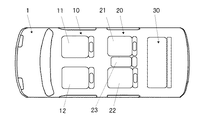
図1は第1実施形態に関わる車両のシート列配置を示す車両平面図である。
車両1には、車両の最前列に配置される第1列シート列10と、その第1列シート列1後方に配置される第2列シート列20と、その第2列シート列2後方に配置される第3シート列30が配置されている。
【0020】
第1シート列10は、運転席11と助手席12とから構成され、第2列シート列20は、運転席11後方に配置される右側第2席21と、助手席12後方に配置される左側第2席22、及び両第2席21、22との間に配置される補助シート23から構成され、第3シート列30は、2名若しくは3名の乗員の着座が可能なベンチタイプのベンチシートによって構成される。
【0021】
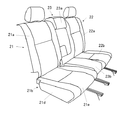
次に、図2に基づき補助シート23が配置される第2シート列20について、説明する。
【0022】
図2は、第2シート列20を右側方側から見た斜視図であって、右側第2席21、左側第2席22は、それぞれシートバック21a及びシートクッション21b、シートバック22a及びシートクッション22bとから構成されている。
また、右側第2席21のシートクッション21bは、上方が開口された収納凹部21c(図2では不図示)を有するクッション本体21dと、収納凹部21cの開口を開閉自在に覆うとともに乗員の着座が可能とされるクッション座部21eとを備えている。
【0023】
また、補助シート23は、補助シートバック23aと、その補助シートバックとは別体の補助シートクッション23bとから構成されている。
補助シートバック23aは、後述するように、その上端側が、右側第2席21のシートバック21aの側部に着脱可能に支持されるとともに、下端側が右側第2席21の側部に回動可能に枢支されている。
【0024】
一方、補助シートクッション23bは、後述するように、右側第2席21のシートクッション21bの側部に位置する着座状態と、上記収納凹部21c内に収納される収納状態とを選択可能に取付けられている。
【0025】
次に、図3乃至図6に基づき補助シートクッション23bの収納凹部21c内への収納について、説明する。
【0026】
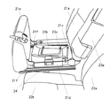
図3は、クッション座部21eの後端側を上方に回動した状態において第2シート列20を右側方側から見た斜視図、図4は、補助シートクッション23bを収納凹部21c内に収納した状態において第2シート列20を右側方側から見た斜視図、図5は、補助シートクッション23bを収納凹部21c内に収納した状態において第2シート列20を左側方側から見た斜視図、図6は補助シートクッション23bを収納凹部21c内に収納した後クッション座部21eを再び着座可能とした状態において第2シート列20を右側方側から見た斜視図である。
補助シートクッション23bの収納凹部21cへの収納に際しては、まず、図3に示すように、クッション座部21eを前方側左右二箇所に設けられた支持部21f、21f(図3では、右側の支持部21fのみ図示)を基点として補助シートクッション23bの後方側を上方に回動し、収納凹部21cの上部側を開口する。
【0027】
また、補助シートクッション23bは、クッション本体21dの側壁に取付部材24によって取付けられており、その取付部材24は、補助シートクッション23bが右側第2席21のシートクッション21bの側方に位置し、乗員の着座が可能な着座状態と、収納凹部21c内に収納される収納状態とを選択できるよう車幅方向に揺動可能とされている。
【0028】
尚、23cは、補助シートクッション23bの底部に設けられ、折り畳み可能な脚部であり、補助シート23使用時は、図3に示すようにフロアと当接するよう位置させ乗員の荷重を支えるととともに、補助シート不使用時は、補助シートクッション23b底部に折り畳むことが可能とされる。
【0029】
次に、図4に示すように、図3に示す状態から、補助シートクッション23bを右側第2席21側に揺動して収納凹部21c内に収納し、その後図5に示すように、脚部23cを折り畳む。
【0030】
そして、図6に示すように、図5に示す状態から、クッション座部21eの後方側を下方側に回動し、収納凹部21cの上部側の開口を閉塞する。
以上のように、補助シート23不使用時は、補助シートクッション23bを収納凹部21c内に収納することができる。
【0031】
次に、図7乃至図9に基づき、補助シートバック23aの構造及び補助シートバック23aの使用モード変更について、説明する。
図7は、補助シートバック23aを第1シート列10乃至第3シート列30の間においてウォークスルーを可能とするウォークスルーモードとした状態において第2シート列20前方側から見た正面図、図8は、補助シートバック23aを第1シート列10乃至第3シート列30の間においてウォークスルーを可能とするウォークスルーモードにした状態において補助シートバック23aを左側方から見た斜視図、図9は、補助シートバック23aをアームレストとしての使用を可能とするアームレストモードにした状態において補助シートバック23aを左側方から見た斜視図である。
【0032】
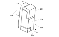
補助シートバック23aは、右側第2席21のシートバック21aの下方側側面に仮想線で示す回動軸C1によって車両前後方向に回動可能に枢支される第1シートバック部23d、その第1シートバック部23d上方側に配置され、第1シートバック部23dの上面に仮想線で示す回動軸C2によって車幅方向に回動可能に枢支される第2シートバック部23e及び第3シートバック23fとから構成されている。
【0033】
尚、第3シートバック部23fは、ヘッドレストとして使用可能とされている。
【0034】
次に、補助シートバック23aのモードについて、説明する。
補助シートバック23aは、使用モード、ウォークスルーモード、及びアームレストモードとの三つのモードに変更可能に構成されている。
【0035】
まず、使用モードについて、説明する。
【0036】
使用モードは、補助シートバック23aをシートバックとして使用するモードであって、補助シートバック23aは、図2乃至図6に示すように、右側第2席21のシートバック21aと左側第2席22のシートバック22aとの間に略隙間なく配置され、シートバックとして使用される。
【0037】
次に、ウォークスルーモードについて、説明する。
【0038】
ウォークスルーモードは、第2シートバック部23e及び第3シートバック部23fを車幅方向に折り畳み、右側第2席21のシートバック21aと左側第2席22のシートバック22aとの間に隙間を形成して前後のシート間におけるウォークスルーを可能にするモードであって、図7、図8に示すように第2シートバック23e及び第3シートバック部23fを、図8中矢印Aで示すように、車両後方側に回動(第1回動状態)させることによって、第2シートバック部23e及び第3シートバック部23fの左側第2席22側側面が車両後方側に位置されるとともに、右側第2席21側側面が車両前方側に位置され、右側第2席21のシートバック21aと左側第2席22のシートバック22aとの間に隙間を形成して、ウォークスルーを可能にする。
【0039】
最後に、アームレストモードについて、説明する。
【0040】
アームレストモードは、補助シート23不使用時、補助シートバック23aをアームレストとして使用するモードであって、図8に示す状態から、図9中矢印Bで示すように、補助シートバック23aを略水平状態となるまで車両前方側に回動(第2回動状態)し、補助シートバック23aの左側第2席22側側面を上方に位置させることによって、補助シートバック23aの左側第2席22側側面をアームレストとして使用可能にする。
【0041】
尚、アームレストモードは、図10に示すように、ウォークスルーモードを介することなく、使用モードから補助シートバック23aを車両前方に回動し、補助シートバック23aの背面を上方に位置させ、その背面をアームレストとして使用することも可能である。
【0042】
ただし、図10に示す場合は、図9に示す場合に対してアームレストとして使用する面が、低く位置することになる。
【0043】
以上のように、本実施形態によれば、補助シートクッション23bと補助シートバックaとが別体に構成され、その内補助シートクッション23bのみが収納凹部21c内に収納可能に構成されるため、収納凹部21c内の深さ(高さ)を抑制することができ、補助シート23が収納される右側第2席21の着座ポイントが高くなることに起因する着座性の悪化を抑制することができる。
【0044】
また、補助シートバック23aは、上端側が着脱可能に支持されるとともに、下端側が車両前後方向に回動可能に枢支されるため、補助シートバック23aをテーブルやアームレストとして利用することができ、別部材を設けることなく利便性を向上することができる。
【0045】
また、補助シートクッション23aは、補助シートクッション23aを車幅方向に揺動自在に枢支する支持部21f、21fを備えるよう構成されるため、補助シートクッション23aを右側第2席21の収納凹部21c内に容易に収納することができる。
【0046】
また、車幅方向に回動され補助シートバック23aの背面が車幅方向に向く第1回動状態と、第1回動状態から車両前方側に回動され補助シートバック23aの側面が上方に向く第2回動状態とを選択可能にとり得る回動機構(回動軸C1、C2)を備えるよう構成されているため、補助シート23不使用時、補助シートバック23aを車幅方向に回動するとともに、車両前方側に回動することによって、補助シートバック23aの側面を高く位置させることができるため、補助シートバック23aをアームレストとして利用することができ、利便性を向上することができる。
【0047】
また、補助シートクッション23bのみ収納凹部21c内に収納すとともに、補助シートバック23aを車幅方向に折り畳むだけの簡単な作業によって、右側第2席21と左側第2席22間のウォークスルースペースを容易に確保することができる。
【0048】
尚、本実施形態では、補助シート23を第2列シート列20の右側第2席21と左側第2席22との間に配置する例を示したが、その他、第3列シート列30をベンチタイプではない通常の独立した二つのシートとし、そのシート間に配置される補助シート23に、本発明を適用するようにしてもよい。
【0049】
また、本実施形態では、補助シート23を第2列シート列20の右側第2席21と左側第2席22との間に配置する例を示したが、その他、左右のシートの内、いずれか一方のシートのドア側側方に配置される補助シート23に、本発明を適用するようにしてもよい。
【0050】
また、本実施形態では、補助シート23を隣接する右側第2席21のシートクッション21b側部に着脱可能に取付ける例を示したが、その他、車両のフロアに着脱可能に取付けるようにしてもよい。
【図面の簡単な説明】
【図1】第1実施形態に関わる車両のシート列配置を示す車両平面図。
【図2】第1実施形態に関わる第2シート列を右側方側から見た斜視図。
【図3】第1実施形態に関わるクッション座部の後端側を上方に回動した状態において第2シート列を右側側方から見た斜視図。
【図4】第1実施形態に関わる補助シートクッションを収納凹部に収納した状態において第2シート列を右側側方から見た斜視図。
【図5】第1実施形態に関わる補助シートクッションを収納凹部に収納した状態において第2シート列を左側側方から見た斜視図。
【図6】第1実施形態に関わる補助シートクッションを収納凹部に収納した後クッション座部を再び着座可能とした状態において第2シート列を右側側方から見た斜視図。
【図7】第1実施形態に関わる補助シートバックをウォークスルーモードとした状態において第2シート列を前方側から見た正面図。
【図8】第1実施形態に関わる補助シートバックをウォークスルーモードとした状態において補助シートバックを左側方から見た斜視図。
【図9】第1実施形態に関わる補助シートバックをアームレストモードとした状態において補助シートバックを左側方から見た斜視図。
【図10】その他の実施形態に関わる補助シートバックをアームレストモードとした状態において補助シートバックを左側方から見た斜視図。
【符号の説明】
1:車両
21:右側第2席
21a:右側第2席シートバック
21b:右側第2席シートクッション
21c:収納凹部
21d:クッション本体
21e:クッション座部
21f:支持部(揺動機構)
21b:右側第2席シートクッション
22:左側第2席
22a:左側第2席シートバック
22b:左側第2席シートクッション
23:補助シート
23a:補助シートバック
23b:補助シートクッション
23c:脚部
23d:第1シートバック部
23e:第2シートバック部
23f:第3シートバック部
24、24:支持部(揺動機構)
C1:第2回動軸
C2:第1回動軸 [0001]
BACKGROUND OF THE INVENTION
The present invention relates to a vehicle seat device, and more particularly to a seat device provided with an auxiliary seat on the side of the seat.
[0002]
[Prior art]
Conventionally, in a vehicle seat device, it can be stored in order to achieve both a relatively relaxed rideability when the number of occupants is small and a passenger occupancy when a large number of occupants ride temporarily. An auxiliary sheet is provided.
For example,
[0003]
[Patent Document 1]
Japanese Patent Laid-Open No. 2002-225603
[Problems to be solved by the invention]
However, the above-described prior art has the following problems.
In other words, since the auxiliary seat disclosed in the above-described prior art has the auxiliary seat back and the auxiliary seat cushion integrated, it is necessary to store the auxiliary seat cushion and the auxiliary seat back together in the storage box. is there.
Therefore, since the depth of the storage box needs to be set to a depth that allows the auxiliary seat cushion and the auxiliary seat back to be stored together, the seating point of the seat becomes high, which may affect riding comfort. .
[0005]
In general, when an occupant sits on a seat, it is desirable to provide a table or an armrest on the side of the seat from the viewpoint of improving convenience.
However, as in the above-described prior art, when the auxiliary sheet can be stored in the side of the seat so that the auxiliary sheet can be stored, the space on the side of the sheet needs to be widened in consideration of the attachment of the auxiliary sheet. Arranging a table or an armrest as a separate member becomes difficult due to the limited space in the vehicle width direction.
[0006]
The present invention has been made in consideration of the above problems, and its purpose is to store the auxiliary seat when the auxiliary seat is not used without deteriorating the riding comfort of the seat in which the auxiliary seat is stored. In addition, the auxiliary sheet can be used for other purposes without providing a separate member.
[0007]
[Means for Solving the Problems]
In order to achieve the above object, the present invention provides the following solution as a solution. That is, in the first aspect of the present invention, the left and right seat arranged at a predetermined distance from each other the seat cushion and the seat back in a closed-to and the vehicle width direction, and an auxiliary sheet disposed between the both sheets a seat apparatus for a vehicle with upper Symbol auxiliary sheet, an auxiliary seat back and, separate from the said auxiliary seat back is pivotally supported to the side surface of the seat back of one sheet of the above left and right seat And an auxiliary seat cushion provided on a side of the seat cushion on a lower side of the auxiliary seat back, and a first rotation shaft extending in a vertical direction on a side surface of the seat back of the one seat Is attached and supported, and the auxiliary seat back is pivotally supported on the side surface of the seat back of the one seat via the first pivot shaft, and has a backrest. The use state in which the surface faces the front side of the vehicle, and the backrest surface on the side of the seat back and the rear side of the vehicle by being rotated from the use state to the rear side of the vehicle around the first rotation axis. The seat cushion of the one seat or the other seat is configured to be capable of selectively switching between the first rotation state facing the width direction, the cushion body having a storage recess opened upward, and the above and a cushion seat which covers the opening of the storage recess openably the auxiliary seat cushion, a seating state is positioned on the side of the seat cushion above the storage recess is provided, the accommodated state is housed in the housing in the recess Can be selectively switched .
[0008]
According to the first configuration of the present invention, the auxiliary seat cushion and the auxiliary seat back are configured separately, and only the auxiliary seat cushion is configured to be stored in the storage recess, so that the depth in the storage recess is reduced. The height (height) can be suppressed, and the deterioration of the seating property due to an increase in the seating point of the seat in which the auxiliary seat is stored can be suppressed .
[0009]
In addition, the auxiliary seat is located between the two seats, and only the auxiliary seat cushion is stored in the storage recess, and the auxiliary seat back is folded in the vehicle width direction, making the walk-through space between the left and right seats easy. Can be secured.
[0010]
In the second configuration of the present invention, the seat cushion provided with the storage recess is configured to include a swing mechanism that pivotally supports the auxiliary seat cushion in the vehicle width direction.
[0011]
According to the second configuration of the present invention, the auxiliary seat cushion is configured to include a swing mechanism that pivotally supports the auxiliary seat cushion so as to be swingable in the vehicle width direction. The sheet can be easily stored in the storage recess of the sheet.
[0012]
In the third configuration of the present invention, the auxiliary seat back has a first seat back portion that constitutes a lower end portion of the auxiliary seat back, and a second seat back portion that is attached to an upper surface of the first seat back portion. The first seat back portion is mounted and supported on a side surface of the seat back of the one seat, and the first rotation shaft is located above the upper surface of the first seat back portion in the use state. And is mounted and supported on the side of the seat back of the one seat via the first seat back portion, and is configured to rotatably support the second seat back portion on the vehicle rear side. The auxiliary seat back is configured to be switchable from the use state to the first turning state by turning the second seat back portion around the first turning shaft toward the vehicle rear side. And Aru.
[0013]
Further, in the fourth configuration of the present invention, the side surface of the seat back of the one seat projects to the auxiliary seat side and extends in the vehicle width direction, and the first seat back portion is rotatably supported. 2 and rotating shaft provided, the auxiliary seat back from the first rotation state, the first seat back portion together with the first pivot axis to said second pivot axis toward the front of the vehicle By turning , the auxiliary seat back can be switched to a second turning state in which the side surface on the vehicle rear side in the first turning state faces upward .
[0014]
Here, when using the auxiliary seat back as an armrest, if the back position of the auxiliary seat back is a relatively low position near the seat cushion simply by rotating the auxiliary seat back forward of the vehicle, the auxiliary seat back It is difficult to use as an armrest.
[0015]
According to the fourth configuration of the present invention, the first rotating state that is rotated in the vehicle width direction and the back surface of the auxiliary seat back faces the vehicle width direction, and the first rotating state is rotated to the front side of the vehicle. Since the auxiliary seat back is configured to be selectable in the second turning state in which the side surface of the auxiliary seat back is directed upward, the auxiliary seat back is rotated in the vehicle width direction when the auxiliary seat is not used. By rotating, the side surface of the auxiliary seat back can be positioned higher, so that the auxiliary seat back can be used as an armrest, and convenience can be improved.
[0016]
In the fifth configuration of the present invention, the auxiliary seat back is disposed without a gap between the seat backs of the left and right seats in the use state.
[0017]
【The invention's effect】
According to the present invention, the auxiliary seat can be stored when the auxiliary seat is not used without deteriorating the riding comfort of the seat in which the auxiliary seat is stored, and the auxiliary seat can be attached to another seat without providing a separate member. It can also be used for purposes, and convenience can be improved.
[0018]
DETAILED DESCRIPTION OF THE INVENTION
Hereinafter, embodiments of the present invention will be described with reference to the drawings.
[0019]
FIG. 1 is a vehicle plan view showing a vehicle seat row arrangement according to the first embodiment.
The
[0020]
The
[0021]
Next, the
[0022]
FIG. 2 is a perspective view of the
Further, the
[0023]
The
As will be described later, the auxiliary seat back 23a is removably supported at the side of the seat back 21a of the right
[0024]
On the other hand, as will be described later, the
[0025]
Next, storage of the
[0026]
3 is a perspective view of the
When the
[0027]
The
[0028]
[0029]
Next, as shown in FIG. 4, from the state shown in FIG. 3, the
[0030]
Then, as shown in FIG. 6, from the state shown in FIG. 5, the rear side of the
As described above, when the
[0031]
Next, based on FIG. 7 thru | or FIG. 9, the structure of the auxiliary seat back 23a and the use mode change of the auxiliary seat back 23a are demonstrated.
FIG. 7 is a front view of the
[0032]
The auxiliary seat back 23a includes a first seat back
[0033]
The third seat back
[0034]
Next, the mode of the auxiliary seat back 23a will be described.
The auxiliary seat back 23a is configured to be changeable into three modes including a use mode, a walk-through mode, and an armrest mode.
[0035]
First, the use mode will be described.
[0036]
The use mode is a mode in which the auxiliary seat back 23a is used as a seat back. As shown in FIGS. 2 to 6, the auxiliary seat back 23a includes the seat back 21a of the right
[0037]
Next, the walk-through mode will be described.
[0038]
In the walk-through mode, the second seat back
[0039]
Finally, the armrest mode will be described.
[0040]
The armrest mode is a mode in which the
[0041]
As shown in FIG. 10, in the armrest mode, the auxiliary seat back 23a is rotated forward from the use mode without going through the walk-through mode, and the back surface of the auxiliary seat back 23a is positioned upward. Can be used as an armrest.
[0042]
However, in the case shown in FIG. 10, the surface used as the armrest is positioned lower than in the case shown in FIG.
[0043]
As described above, according to the present embodiment, the
[0044]
Further, the auxiliary seat back 23a is supported detachably at the upper end side and pivotally supported at the lower end side so as to be pivotable in the vehicle front-rear direction. Therefore, the auxiliary seat back 23a can be used as a table or an armrest. Convenience can be improved without providing a member.
[0045]
Further, since the
[0046]
In addition, the first rotational state in which the back surface of the auxiliary seat back 23a is rotated in the vehicle width direction and the back surface of the auxiliary seat back 23a is directed in the vehicle width direction, and the side surface of the auxiliary seat back 23a is rotated upward from the first rotational state. Since the rotation mechanism (rotation shafts C1 and C2) that can select the second rotation state that faces is selectable, the auxiliary seat back 23a is rotated in the vehicle width direction when the
[0047]
Further, only the
[0048]
In the present embodiment, the
[0049]
In the present embodiment, the
[0050]
In the present embodiment, the
[Brief description of the drawings]
FIG. 1 is a plan view of a vehicle showing an arrangement of seat rows of a vehicle according to a first embodiment.
FIG. 2 is a perspective view of a second sheet row according to the first embodiment viewed from the right side.
FIG. 3 is a perspective view of a second seat row as viewed from the right side in a state where the rear end side of the cushion seat portion related to the first embodiment is rotated upward.
FIG. 4 is a perspective view of the second seat row viewed from the right side in a state where the auxiliary seat cushion according to the first embodiment is housed in the housing recess.
FIG. 5 is a perspective view of the second seat row viewed from the left side in a state where the auxiliary seat cushion according to the first embodiment is housed in the housing recess.
FIG. 6 is a perspective view of the second seat row as viewed from the right side in a state where the cushion seat portion can be seated again after the auxiliary seat cushion according to the first embodiment is stored in the storage recess.
FIG. 7 is a front view of the second sheet row as viewed from the front side in a state where the auxiliary seat back according to the first embodiment is in a walk-through mode.
FIG. 8 is a perspective view of the auxiliary seatback viewed from the left side in a state where the auxiliary seatback according to the first embodiment is set to a walk-through mode.
FIG. 9 is a perspective view of the auxiliary seatback viewed from the left side in a state where the auxiliary seatback according to the first embodiment is in the armrest mode.
FIG. 10 is a perspective view of the auxiliary seatback viewed from the left side in a state where the auxiliary seatback according to another embodiment is in the armrest mode.
[Explanation of symbols]
1: Vehicle 21: Right
21b: right second seat cushion 22: left
C1 : Second rotation axis C2 : First rotation axis
Claims (5)
上記補助シートは、上記左右のシートのうちの一方のシートのシートバックの側面に枢支される補助シートバックと、該補助シートバックとは別体に構成され、上記補助シートバックの下方側において、上記シートクッションの側方に設けられる補助シートクッションとを備え、
上記一方のシートのシートバックの側面には、上下方向に延びる第1回動軸が取付支持されており、
上記補助シートバックは、上記一方のシートのシートバックの側面において上記第1回動軸を介して回動可能に枢支されていて、背もたれ面が車両前方側を向く使用状態と、該使用状態から該第1回動軸回りに車両後方側に回動されることで該背もたれ面が該シートバックの側方且つ車両後方側にて車幅方向を向く第1回動状態とを選択的に切換え可能に構成されており、
上記一方のシート又は他方のシートのシートクッションは、上方に向かって開口した収納凹部を有するクッション本体と、上記収納凹部の開口を開閉自在に覆うクッション座部とを備え、
上記補助シートクッションは、上記収納凹部が設けられるシートクッションの側方に位置する着座状態と、上記収納凹部内に収納される収納状態とを選択的に切換え可能に構成されていることを特徴とする車両のシート装置。A seat apparatus for a vehicle with a right and left seat arranged at a predetermined distance from each other in and the vehicle width direction have a seat cushion and a seat back, and an auxiliary sheet disposed between the both sheets,
Upper Symbol auxiliary sheet, an auxiliary seat back is pivotally supported to the side surface of the seat back of one sheet of the above left and right seat, and the auxiliary seat back is configured separately, below the auxiliary seat back Side, provided with an auxiliary seat cushion provided on the side of the seat cushion,
A first rotating shaft extending in the vertical direction is attached and supported on the side surface of the seat back of the one seat,
The auxiliary seat back is pivotally supported on the side surface of the seat back of the one seat via the first rotation shaft, and the backrest surface faces the vehicle front side, and the use state From the first turning state in which the backrest surface is directed in the vehicle width direction on the side of the seat back and on the vehicle rear side. It is configured to be switchable,
The seat cushion of the one seat or the other seat includes a cushion body having a storage recess that opens upward, and a cushion seat that covers the opening of the storage recess so as to be openable and closable .
The auxiliary seat cushion, and features that you have been selectively switchably configured with the seating state located on the side of the seat cushion above the storage recess is provided, and a storage state of being housed in the housing in the recess A vehicle seat device.
上記第1シートバック部は、上記一方のシートのシートバックの側面に取付支持されており、The first seat back part is attached and supported on the side surface of the seat back of the one seat,
上記第1回動軸は、上記使用状態において、上記第1シートバック部の上面から上方側に突出して該第1シートバック部を介して上記一方のシートのシートバックの側面に取付支持されるとともに、上記第2シートバック部を車両後方側に回動可能に支持するように構成され、The first rotating shaft protrudes upward from the upper surface of the first seat back portion and is attached and supported on the side surface of the seat back of the one seat through the first seat back portion in the use state. And is configured to rotatably support the second seat back portion on the vehicle rear side,
上記補助シートバックは、上記使用状態から、上記第2シートバック部を上記第1回動軸回りに車両後方側に回動させることで、上記第1回動状態に切換え可能に構成されていることを特徴とする請求項1又は2に記載の車両のシート装置。The auxiliary seat back is configured to be switchable from the use state to the first turning state by turning the second seat back portion around the first turning shaft toward the vehicle rear side. The vehicle seat device according to claim 1, wherein the vehicle seat device is a vehicle seat device.
上記補助シートバックは、上記第1回動状態から、上記第1シートバック部を上記第1回動軸とともに上記第2回動軸回りに車両前方側に回動させることで、該補助シートバックの上記第1回動状態における車両後方側の側面が上方を向く第2回動状態に切換え可能に構成されていることを特徴とする請求項3に記載の車両のシート装置。 A side surface of the seat back of the one seat is provided with a second rotating shaft that protrudes toward the auxiliary seat side and extends in the vehicle width direction and rotatably supports the first seat back portion,
The auxiliary seat back from the first rotation state, the first seat back portion by rotating the vehicle front side to the second rotation axis together with the first pivot axis, said auxiliary sheet seat device for a vehicle according to claim 3 in which the side surface of the vehicle rear side is characterized that you have been configured to be switched to the second rotation state facing upward in the back of the first rotation state.
Priority Applications (3)
| Application Number | Priority Date | Filing Date | Title |
|---|---|---|---|
| JP2003040570A JP4135523B2 (en) | 2003-02-19 | 2003-02-19 | Vehicle seat device |
| EP04002797A EP1449710B1 (en) | 2003-02-19 | 2004-02-09 | Seat device including a stowable auxiliary seat |
| US10/774,433 US6811200B2 (en) | 2003-02-19 | 2004-02-10 | Seat device for vehicle |
Applications Claiming Priority (1)
| Application Number | Priority Date | Filing Date | Title |
|---|---|---|---|
| JP2003040570A JP4135523B2 (en) | 2003-02-19 | 2003-02-19 | Vehicle seat device |
Publications (2)
| Publication Number | Publication Date |
|---|---|
| JP2004249782A JP2004249782A (en) | 2004-09-09 |
| JP4135523B2 true JP4135523B2 (en) | 2008-08-20 |
Family
ID=32732931
Family Applications (1)
| Application Number | Title | Priority Date | Filing Date |
|---|---|---|---|
| JP2003040570A Expired - Fee Related JP4135523B2 (en) | 2003-02-19 | 2003-02-19 | Vehicle seat device |
Country Status (3)
| Country | Link |
|---|---|
| US (1) | US6811200B2 (en) |
| EP (1) | EP1449710B1 (en) |
| JP (1) | JP4135523B2 (en) |
Families Citing this family (46)
| Publication number | Priority date | Publication date | Assignee | Title |
|---|---|---|---|---|
| JP2003312442A (en) * | 2002-04-24 | 2003-11-06 | Johnson Controls Automotive Systems Corp | Vehicular rear seat device |
| JP4216147B2 (en) * | 2003-02-13 | 2009-01-28 | 本田技研工業株式会社 | Vehicle seat |
| CA2459073A1 (en) * | 2003-02-21 | 2004-08-21 | Michel Swift | Seat for motor vehicle |
| EP1493624B1 (en) * | 2003-07-02 | 2006-10-04 | Mazda Motor Corporation | Combination structure of storage box and center seat for vehicle |
| US7090274B1 (en) * | 2005-02-11 | 2006-08-15 | Nissan Technical Center North America, Inc. | Vehicle storage structure |
| PL1912823T3 (en) * | 2005-08-04 | 2012-08-31 | Johnson Controls Tech Co | Configurable seating and console system |
| JP4706393B2 (en) * | 2005-08-26 | 2011-06-22 | マツダ株式会社 | Vehicle seat device |
| JP4534913B2 (en) * | 2005-08-30 | 2010-09-01 | マツダ株式会社 | Vehicle seat device |
| JP4622760B2 (en) * | 2005-09-09 | 2011-02-02 | マツダ株式会社 | Vehicle seat device |
| JP4622759B2 (en) * | 2005-09-09 | 2011-02-02 | マツダ株式会社 | Vehicle seat device |
| JP2007083787A (en) * | 2005-09-20 | 2007-04-05 | Mazda Motor Corp | Vehicular seat device |
| DE102005046876A1 (en) * | 2005-09-29 | 2007-04-05 | Faurecia Autositze Gmbh | Seat row of a motor vehicle with an arranged between two outer seats armrest |
| US20070085363A1 (en) * | 2005-10-13 | 2007-04-19 | Lear Corporation | Console assembly for a vehicle |
| JP2007191039A (en) * | 2006-01-19 | 2007-08-02 | Mazda Motor Corp | Seat device for vehicle |
| JP2007191040A (en) * | 2006-01-19 | 2007-08-02 | Mazda Motor Corp | Seat device for vehicle |
| JP2007203766A (en) * | 2006-01-31 | 2007-08-16 | Mazda Motor Corp | Seat device for vehicle |
| JP4972941B2 (en) * | 2006-01-31 | 2012-07-11 | マツダ株式会社 | Vehicle seat device |
| DE102006010376A1 (en) * | 2006-03-03 | 2007-09-06 | Bos Gmbh & Co. Kg | Rear seat back with height-adjustable center armrest |
| US7775577B2 (en) * | 2006-10-25 | 2010-08-17 | Faurecia Autositze Gmbh | Vehicle seat arrangement |
| JP4306735B2 (en) * | 2007-01-31 | 2009-08-05 | トヨタ自動車株式会社 | Vehicle seat |
| DE102007005143A1 (en) * | 2007-02-01 | 2008-08-07 | Faurecia Autositze Gmbh | Vehicle seat assembly |
| DE102007005144C5 (en) | 2007-02-01 | 2017-04-13 | Faurecia Autositze Gmbh | Motor vehicle with a vehicle seat arrangement |
| DE102007053958B4 (en) | 2007-02-26 | 2016-04-28 | Johnson Controls Gmbh | vehicle seat |
| US7490896B2 (en) * | 2007-04-10 | 2009-02-17 | Lear Corporation | Stowable component for a vehicle and a method for stowing a vehicular component |
| DE102007055081B4 (en) | 2007-07-05 | 2013-11-07 | Johnson Controls Gmbh | Vehicle seat with securing means for a support element |
| US7845724B2 (en) * | 2007-09-14 | 2010-12-07 | CCO Holding Corp. | Automotive seating configuration |
| DE102007055144A1 (en) | 2007-11-19 | 2009-05-20 | Ford-Werke Gmbh | Seat i.e. middle seat, for use in seat arrangement in vehicle, has back part longitudinally-changeable between one final position at which back part exhibits greater length formed as seat length and another final position |
| DE102008029261A1 (en) * | 2008-06-19 | 2009-12-24 | GM Global Technology Operations, Inc., Detroit | Seating arrangement for motor vehicle, has two vehicle seats, which are arranged side by side in transverse direction under formation of gap, where backrest part or seat part of auxiliary seat is fixed |
| WO2010039639A1 (en) * | 2008-09-30 | 2010-04-08 | Johnson Controls Technology Company | Folding seat system |
| DE102008050301B4 (en) * | 2008-10-02 | 2013-08-14 | Lear Corp. | Automotive seat system |
| DE102009021211B4 (en) * | 2009-05-13 | 2013-08-08 | Johnson Controls Gmbh | vehicle seat |
| JP4743310B2 (en) | 2009-07-08 | 2011-08-10 | マツダ株式会社 | Vehicle seat device |
| US7980617B2 (en) * | 2009-07-15 | 2011-07-19 | Cosco Management, Inc. | Vehicle seat with back-support and shoulder-support wings |
| DE102009038440B4 (en) * | 2009-08-21 | 2018-06-14 | GM Global Technology Operations LLC (n. d. Ges. d. Staates Delaware) | Motor vehicle with a row of seats with two outer seats and a center seat |
| JP5418139B2 (en) * | 2009-10-22 | 2014-02-19 | マツダ株式会社 | Vehicle seat device |
| JP5418143B2 (en) * | 2009-10-23 | 2014-02-19 | マツダ株式会社 | Vehicle seat device |
| US8313146B2 (en) * | 2010-01-20 | 2012-11-20 | Ford Global Technologies, Llc | Stowable vehicle seat |
| FR2979863B1 (en) * | 2011-09-09 | 2014-03-07 | Peugeot Citroen Automobiles Sa | SEATABLE SEAT SEAT DEVICE FOR VEHICLE CABINET |
| US9168850B2 (en) * | 2013-12-19 | 2015-10-27 | Ford Global Technologies, Llc | Utility seat assembly |
| US9694755B2 (en) * | 2014-11-26 | 2017-07-04 | GM Global Technology Operations LLC | Seat assembly with removable cushion insert |
| KR101845782B1 (en) | 2016-04-21 | 2018-04-05 | 현대자동차주식회사 | Structure of stowable auxiliary seat for vehicle |
| US10245982B2 (en) * | 2017-02-24 | 2019-04-02 | Ford Global Technologies, Llc | Vehicle seat with laterally collapsing portion |
| US10829020B2 (en) * | 2018-02-01 | 2020-11-10 | Ford Global Technologies, Llc | Vehicle seating arrangement |
| KR20210002186A (en) * | 2019-06-27 | 2021-01-07 | 현대자동차주식회사 | Auxiliary seat storage apparatus of seat |
| US11148556B2 (en) * | 2019-08-09 | 2021-10-19 | Mahindra N.A. Tech Center | Vehicle seat hinge assembly |
| RU198114U1 (en) * | 2020-03-02 | 2020-06-18 | Общество с ограниченной ответственностью "Дакар" | Car seat |
Family Cites Families (9)
| Publication number | Priority date | Publication date | Assignee | Title |
|---|---|---|---|---|
| US808679A (en) * | 1905-02-09 | 1906-01-02 | John A Brill | Disappearing seat. |
| US819537A (en) * | 1905-12-13 | 1906-05-01 | John Gabriel | Railway-rail joint. |
| US1643236A (en) * | 1926-07-26 | 1927-09-20 | Bell Jesse James | Automobile seat |
| JP2000085417A (en) | 1998-09-08 | 2000-03-28 | Ikeda Bussan Co Ltd | Automobile seat |
| JP3673679B2 (en) | 1999-08-10 | 2005-07-20 | トヨタ紡織株式会社 | Vehicle seat |
| DE20017051U1 (en) * | 2000-10-04 | 2002-02-14 | Johnson Controls Gmbh | Seat arrangement for vehicles |
| JP2002225603A (en) * | 2001-01-29 | 2002-08-14 | Johnson Controls Automotive Systems Corp | Vehicle seat |
| US6540279B1 (en) * | 2001-09-07 | 2003-04-01 | Daimlerchrysler Corporation | Underseat storage arrangement |
| US6629729B2 (en) * | 2002-01-04 | 2003-10-07 | Honda Giken Kogyo Kabushiki Kaisha | Rear seat for a vehicle |
-
2003
- 2003-02-19 JP JP2003040570A patent/JP4135523B2/en not_active Expired - Fee Related
-
2004
- 2004-02-09 EP EP04002797A patent/EP1449710B1/en not_active Expired - Fee Related
- 2004-02-10 US US10/774,433 patent/US6811200B2/en not_active Expired - Lifetime
Also Published As
| Publication number | Publication date |
|---|---|
| US20040160080A1 (en) | 2004-08-19 |
| JP2004249782A (en) | 2004-09-09 |
| EP1449710B1 (en) | 2011-10-05 |
| EP1449710A3 (en) | 2007-05-23 |
| EP1449710A2 (en) | 2004-08-25 |
| US6811200B2 (en) | 2004-11-02 |
Similar Documents
| Publication | Publication Date | Title |
|---|---|---|
| JP4135523B2 (en) | Vehicle seat device | |
| US7819468B2 (en) | Seat for vehicle | |
| JP3878099B2 (en) | Vehicle seat arrangement structure | |
| JP2003341398A (en) | Seat disposing structure for vehicle | |
| JP2004262424A (en) | Car seat, car seat accommodating structure, and car seat structure | |
| JP5298580B2 (en) | Vehicle seat | |
| JP2003080982A (en) | Vehicles seat system | |
| JP4569823B2 (en) | Vehicle seat | |
| JP5381092B2 (en) | Vehicle seat device | |
| JP2007008258A (en) | Arm rest structure of vehicle | |
| JP2004243876A (en) | Vehicular sheet housing structure | |
| JP4165200B2 (en) | Auxiliary seat device for vehicle | |
| JP2001001805A (en) | Vehicle center seat mounting structure | |
| JP4442389B2 (en) | Vehicle seat device | |
| JP4059101B2 (en) | Center seat structure for vehicles | |
| JP4135483B2 (en) | Auxiliary seat device for vehicle | |
| JP4952071B2 (en) | Vehicle seat device | |
| JP4279297B2 (en) | Vehicle seat arrangement structure | |
| JP3641166B2 (en) | Seat device with auxiliary seat for automobile | |
| JP2011213154A (en) | Seat device of vehicle | |
| JP2004243975A (en) | Vehicle seat device | |
| JP2011131662A (en) | Vehicle luggage compartment space structure | |
| JP2007153221A (en) | Arm rest structure of vehicle | |
| JP2004182103A (en) | Vehicular auxiliary seat device | |
| JP2532615Y2 (en) | Car seat |
Legal Events
| Date | Code | Title | Description |
|---|---|---|---|
| A621 | Written request for application examination |
Free format text: JAPANESE INTERMEDIATE CODE: A621 Effective date: 20051125 |
|
| RD03 | Notification of appointment of power of attorney |
Free format text: JAPANESE INTERMEDIATE CODE: A7423 Effective date: 20051125 |
|
| A977 | Report on retrieval |
Free format text: JAPANESE INTERMEDIATE CODE: A971007 Effective date: 20080124 |
|
| A131 | Notification of reasons for refusal |
Free format text: JAPANESE INTERMEDIATE CODE: A131 Effective date: 20080129 |
|
| A521 | Written amendment |
Free format text: JAPANESE INTERMEDIATE CODE: A523 Effective date: 20080328 |
|
| TRDD | Decision of grant or rejection written | ||
| A01 | Written decision to grant a patent or to grant a registration (utility model) |
Free format text: JAPANESE INTERMEDIATE CODE: A01 Effective date: 20080513 |
|
| A01 | Written decision to grant a patent or to grant a registration (utility model) |
Free format text: JAPANESE INTERMEDIATE CODE: A01 |
|
| A61 | First payment of annual fees (during grant procedure) |
Free format text: JAPANESE INTERMEDIATE CODE: A61 Effective date: 20080526 |
|
| R150 | Certificate of patent or registration of utility model |
Free format text: JAPANESE INTERMEDIATE CODE: R150 |
|
| FPAY | Renewal fee payment (event date is renewal date of database) |
Free format text: PAYMENT UNTIL: 20110613 Year of fee payment: 3 |
|
| FPAY | Renewal fee payment (event date is renewal date of database) |
Free format text: PAYMENT UNTIL: 20120613 Year of fee payment: 4 |
|
| FPAY | Renewal fee payment (event date is renewal date of database) |
Free format text: PAYMENT UNTIL: 20130613 Year of fee payment: 5 |
|
| LAPS | Cancellation because of no payment of annual fees |