JP3673679B2 - Vehicle seat - Google Patents
Vehicle seat Download PDFInfo
- Publication number
- JP3673679B2 JP3673679B2 JP22669199A JP22669199A JP3673679B2 JP 3673679 B2 JP3673679 B2 JP 3673679B2 JP 22669199 A JP22669199 A JP 22669199A JP 22669199 A JP22669199 A JP 22669199A JP 3673679 B2 JP3673679 B2 JP 3673679B2
- Authority
- JP
- Japan
- Prior art keywords
- seat
- seat cushion
- hooked
- latching
- state
- Prior art date
- Legal status (The legal status is an assumption and is not a legal conclusion. Google has not performed a legal analysis and makes no representation as to the accuracy of the status listed.)
- Expired - Fee Related
Links
Images


Description
【0001】
【発明の属する技術分野】
本発明は、車室内に離脱可能に配設される車両用シートに関する。
【0002】
【従来の技術】
車両においては、車室内に広い空間を形成するために、車室内に配設されている車両用シートが格納される場合がある。この場合、車両用シートを車室内空間の用途に応じた格納状態にする必要があるが、車両用シートによっては的確な格納状態を構成し得ないことがある。この場合には、的確な格納状態を構成し得ない車両用シートを車室内から離脱して収納することが好ましい。離脱の対象となる車両用シートとしては、並列3座席型シートで中央座席を構成するセンターシート、並列2座席型シートで一方の側方座席を構成するサイドシート、3列目座席の側方座席を構成するサイドシート等が該当する。
【0003】
【発明が解決しようとする課題】
ところで、車両用シートを車室内に離脱可能に配設するためには、同シートを支持するための支持部材に対して離脱可能に連結する連結手段を介して連結する必要があり、当該連結手段は、車両用シートの形式、支持される支持部位、支持部材の形状等に適したように、かつ、車両用シートの着脱が容易に行えるように構成することが肝要である。従って、本発明の目的は、これらの問題に対処することにある。
【0004】
【課題を解決するための手段】
本発明は、車両用シートに関するもので、当該車両用シートは、シートクッションの一端が連結手段によってシートクッションの一端に対向する車室内の部位に離脱可能に連結される車両用シートであり、前記連結手段は、前記車室内に固定して設置された掛止部材と、先端に被掛止部を有して前記シートクッションの一端に設けられて側方に突出し、同シートクッションの他端を上方へ回動して車室フロアに略水平状態になったとき、前記掛止部が前記掛止部材の掛止部にに掛止められる被掛止部材とを備え、前記シートクッションの他端を下方へ回動させることにより前記掛止部材と前記被掛止部材との掛止状態が解除されて、前記シートクッションが車室内の部位から離脱可能となることを特徴とするものである。
【0005】
しかして、本発明に係る車両用シートにおいては、前記シートクッションを連結する前記連結手段は、前記掛止部材の上方に設置され、同掛止部材と前記被掛止部材が掛止状態あるとき、同被掛止部材の上面に弾撥的に当接する弾性部材を備える構成とするようにすることができ、前記シートクッションは、同シートクッションの他端に設けた支承部材によって車室フロアに対して略水平状態に支承されるもので、前記支承部材は、前記シートクッションの他端に組付けられて、同シートクッションに対して水平状の倒伏状態と直交状の起立状態とに選択的に保持可能なサイドレッグであって、同サイドレッグを倒伏状態として前記シートクッションの他端を下方へ回動させることにより、前記被掛止部材の被掛止部の前記掛止部材の掛止部との掛止および前記弾性部材との当接が解除され、前記シートクッションが車室内の部位から離脱可能となるように構成とすることができ、また、前記被掛止部材は前記シートクッションの一端から所定の角度をもって側方へ突出していて、同被掛止部材は、前記シートクッションが略水平状態では先端方向の下方へ傾斜して前記掛止部材と掛止状態となり、かつ、前記シートクッションの他端が下方へ回動した状態では略水平状態となるように構成され、前記シートクッションの車室内の部位からの離脱は前記被掛止部材が略水平状態で可能となるように構成することができる。
【0006】
この場合、前記連結手段を構成する被掛止部材を、被ガイド部を備えた構成として、同被ガイド部を前記掛止部材に設けられたガイド部に当接させることにより、前記被掛止部材が前記掛止部材に仮止め状態となるように構成することができ、また、前記連結手段を構成する被掛止部材を、その先端に被掛止部であるフック部を備えた被掛止アームに構成するとともに、前記掛止部材を前記被掛止アームが挿入可能な開口と奥部に掛止部を備えたケース状に構成して、前記被掛止アームを前記掛止部材の開口に挿入することにより前記被掛止部と前記掛止部が仮止め状態となり、仮止め状態において、前記シートクッションを車室フロアに対して略水平とすることにより、前記被掛止部と前記掛止部とが掛止状態となるように構成することができる。
【0007】
本発明に係るこれらの車両用シートの前記連結手段は、隣り合うシート同士を連結し、または、シートと車室壁部とを互いに連結するものである。
【0008】
【発明の作用・効果】
本発明に係る車両用シートにおいては、連結手段が、車室フロアに対して略水平状のシートクッションを所定角度以上回動することにより車室内との連結状態を解除すべく機能するもので、当該車両用シートの車室内での離脱作業が容易であり、連結手段を上記したごとき各構成とすれば、下記のごとき作用効果を奏するものである。
【0009】
すなわち、離脱したシートを車室内に装着するに当っては、先ず、シートに設けられた被掛止部材である被掛止アームを車室内に設けられた掛止部材の開口に挿入することにより、被掛止アームのガイド部が掛止部材のガイド部に当接してシートを仮止めする。次いで、仮止めされた状態の連結手段を軸として、シートクッションを所定角度以上回動する。これにより、被掛止アームはシートクッションを基点として回動して、被掛止アームと掛止部材が互いに掛止状態となって、シートは車室内に連結されて装着される。なお、装着されているシートを離脱させるには、上記とは逆の操作を行えばよい。
【0010】
【発明の実施の形態】
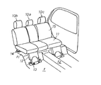
以下、本発明を図面に基づいて説明する。図1には、並列3座席型のリヤシートが示されている。当該リヤシートはダブルフォールドダウンシートであって、中央座席であるセンターシート10aと、左右の各側方座席であるサイドシート10b,10cとにより構成されている。各サイドシート10b,10cは、シートクッション11の下面の前側に回動可能に組付けた脚部12をリンク13を介して車室フロアfに前後方向へ回動可能に支持されているとともに、シートクッション11の下面の後側に設けたロック機構14を介し車室フロアfのデッキf1に離脱可能にロックされている。
【0011】
これら各サイドシート10b,10cは、ロック機構14による車室フロアfのデッキf1に対するロックを解除することにより、図2に示すように、シートバック15をシートクッション11上に折り畳んだ状態で、車室フロアfのデッキf1と略同一レベルになるように、前方へ折り畳んで格納される構成となっている。センターシート10aは本発明の一例に係る車両用シートであり、本発明の主要部をなす連結機構を介してサイドシート10cのシートクッション11の一側に離脱可能に連結されているとともに、サイドレッグを介して車室フロアfのデッキf1上に支承されているもので、車室フロアfのトンネル部f2に対向している。このため、センターシート10aは、サイドシート10cを格納する際には、同サイドシート10cから離脱される構成となっている。
【0012】
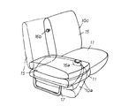
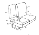
図3および図4には、センターシート10aの2つの例が示されており、図3に示すセンターシート10aにおいては、シートクッション11がサイドシート10cのシートクッション11の一側に対して本発明に係る連結機構を介して離脱可能に連結され、かつ、シートバック15がサイドシート10cのシートバック15の一側に対してバックロック16aをバックストライカ16bに掛止することにより離脱可能に連結される。図4に示すセンターシート10aにおいては、シートクッション11がサイドシート10cのシートクッション11の一側に対して本発明に係る連結機構を介して離脱可能に連結されているもので、シートバック15は、サイドシート10cのシートバック15の一側に対しては連結されておらず、シートクッション11に対して左右一対のリクライニング機構16cを介して連結されている。
【0013】
各センターシート10aは、図3の2点鎖線で示すようにサイドシート10cのシートクッション11から離脱され、かつ、図5に示すように同シートクッション11に連結されるもので、図3または図4に示すように、シートクッション11の下面側に設けたサイドレッグ17を介して車室フロアfのデッキf1上に支承される。なお、図3〜図5のセンターシート10aおよびサイドシート10cは、ヘッドレストを省略して示されている。
【0014】
サイドレッグ17は、パイプを長方状に屈曲して形成されているもので、その各上端部にて、図7に示すように、センターシート10aのシートクッション11を構成するクッションフレーム18の外側部に設けたブラケット18aに支持ピン18bを介して上下方向へ回動可能に組付けられている。サイドレッグ17の一方の上端部と一方のブラケット18a間には、バネ18cが掛止されている。バネ18cは、サイドレッグ17の回動時にターンオーバーするもので、図9および図10に示すように、サイドレッグ17をクッションフレーム18に対して水平状の倒伏状態と、図11に示すように、サイドレッグ17をクッションフレーム18に対して直交した起立状態とに選択的に保持する。
【0015】
しかして、連結機構は図6に示すように、センターシート10aのシートクッション11側に設けた被掛止アーム21と、サイドシート10cのシートクッション11側に設けた掛止部材22を主要構成部材としている。
【0016】
被掛止アーム21は、図6および図7に示すように、センターシート10aのシートクッション11を構成するクッションフレーム18に固着されているもので、クッションフレーム18の内側部に固着された状態で側方へ所定長さ突出している。被掛止アーム21は平板状のもので、図6、図7および図9〜図11に示すように、アーム本体21aの先端に下向きのフック部21bを備えているとともに、アーム本体21aの側部の中央部に内側へ半抜きされて形成された長楕円形状の膨出部21cを備えている。
【0017】
掛止部材22は、図6および図8〜図11に示すように、サイドシート10cのシートクッション11を構成するクッションフレームに設けたサイドフレーム19に固着されている。掛止部材22は、奥壁部22aと、内壁部22bと、外壁部22cとかなる平面略コ字状を呈するもので、各壁部22a〜22cの下端部には脚部22dを備えている。奥壁部22aはその一部が切欠かれていて、切欠部の一部が掛止部22eに形成されている。内壁部22bは、先端側の上端面が曲線状を呈するガイド部22fに形成されているとともに、ガイド部22fの後端部には上方へ突出するストッパ22gが形成されている。
【0018】
掛止部材22は、その各脚部22dをサイドフレーム19の底壁部に設けた各嵌合溝19aに嵌合されて固着されていて、奥壁部22aがサイドフレーム19の起立壁部に設けた開口部19bに対向して位置している。サイドフレーム19の起立壁部に設けた開口部19bには挿入口形成部材23が嵌合固定され、また、サイドフレーム19の上壁部に設けた取付口19cにはゴム等の弾性部材24が嵌着されている。
【0019】
挿入口形成部材23は、長方形のプレート部23aの裏面に断面凸形状の筒部23bを有するもので、筒部23bの先端には裏面側に突出する3本の脚部23cが形成されている。挿入口形成部材23においては、その筒部23bがサイドフレーム19の開口部19bにサイドシート10cの表面被覆材を挟んだ状態で挿入されていて、各脚部23cの先端側の爪を開口部19bの周縁に掛止することによりサイドフレーム19に取付けらている。この取付状態においては、挿入口形成部材23の筒部23bは掛止部材22の奥壁部22aに対向していて、センターシート10aのシートクッション11側の各被掛止アーム21を挿入可能としている。
【0020】
弾性部材24は、平板状の受承部24aと、受承部24aの上面に設けた掛止突起部24bとからなり、一方、サイドフレーム19の上壁部に設けた取付口19cは大径部と小径部が連通した瓢箪形を呈している。弾性部材24は、その掛止突起部24bを取付口19cの大径部から差込んで小径部側へ移動させることにより取付けられていて、受承部24aは、サイドフレーム19に取付けられた状態の掛止部材22の上方開口部の上方にて、挿入口形成部材23の筒部23bの前方かつ上方に位置している。
【0021】
被掛止アーム21と、これらの掛止部材22、挿入口形成部材23および弾性部材24との関係は次のように設定されている。すなわち、挿入口形成部材23の筒部24bの内孔の上下方向の幅寸法は被掛止アーム21の上下方向の幅寸法より所定幅広に形成され、かつ、同筒部24bの内孔の横方向の幅寸法は被掛止アーム21の最大厚み寸法より幅広に形成されている。また、掛止部材22のガイド部22fは、挿入口形成部材23の筒部24bを通して挿入される被掛止アーム21の膨出部21cを受承し得る位置にあり、ストッパ22gは被掛止アーム21のフック部21bが通過して膨出部21cの先端が当接し得る位置にあり、かつ、掛止部22eは膨出部21cの先端がストッパ22gに当接した状態でフック部21bが上方に臨む位置にある。また、弾性部材24の受承部24aは、最大限の挿入状態にある被掛止アーム21のわずかに上方に位置している。
【0022】
かかる構成の連結機構においては、前後一対の被掛止アーム21がセンターシート10aのシートクッション11側に設けられ、かつ、前後一対の掛止部材22がサイドシート10cのシートクッション11側に設けられている。センターシート10aは、各被掛止アーム21を各掛止部材22に掛止することによりサイドシート10cに連結され、かつ、サイドレッグ17を起立状態に保持することにより車室フロアfのデッキf1上に支承されて図1に示す状態に配設されている。
【0023】
センターシート10aは、両サイドシート10b,10cを図2に示すようにフォールドダウン状態に格納する際にはサイドシート10cから離脱されるが、先ずサイドシート10bをフォールドダウン状態に格納して図3または図4に示す状態とし、図5に示すように、サイドシート10cのシートクッション11から離脱させる。また、センターシート10aをサイドシート10cに取着する場合も同様である。センターシート10aのサイドシート10cに対する着脱時の連結機構の動作状態が図9〜図11に示されており、連結機構は、センターシート10aのサイドシート10cに対する取着時には図9から図11の順に動作し、センターシート10aのサイドシート10cに対する離脱時には図11から図9の順に動作する。
【0024】
図9に示すサイドシート10cは、車室フロアfのデッキf1上に起立状態に保持されているもので、センターシート10aは折畳まれた状態でサイドシート10cのシートクッション11側に連結される。センタシート10aは、連結に当たっては、図9に示すようにデッキf1に対してわずかに外側へ下降傾斜した状態とする。これにより、センターシート10aのシートクッション11側の各被掛止アーム21は同図に示すようにデッキf1に対して略水平状態となり、この状態の各被掛止アーム21を先端側から挿入口形成部材23の筒部23bを通して掛止部材22内に挿入する。
【0025】
各被掛止アーム21の掛止部材22内への挿入時には、被掛止アーム21の膨出部21cが掛止部材22のガイド部22fに受承された状態で摺動して、被掛止アーム21が所定量挿入した時点で膨出部21cの先端が掛止部材22のストッパ22gに当接し、それ以上の挿入が規制される。図10は、被掛止アーム21が掛止部材22内に最大限挿入された状態を示しており、被掛止アーム21が掛止部材22内に最大限挿入された状態では、被掛止アーム21のフック部21bは掛止部材22の掛止部22e上にあり、また、被掛止アーム21の上端面は弾性部材24の受承部24aの下面に当接している。
【0026】
この状態のセンターシート10aを略水平状態に持上げると、各被掛止アーム21は、クッションフレーム18の内側部を略中心として図10の図示時計方向へ回動し、図11に示すように、被掛止アーム21のフック部21bは掛止部材22の掛止部22eに上方から掛止され、かつ、被掛止アーム21の上端面の一部が弾性部材24の受承部24aに弾撥的に当接する。次いで、折畳まれた状態のサイドレッグ17をバネ18cに抗して図示時計方向へ回動すれば、サイドレッグ17は支持ピン18bを中心に回動して起立するとともに、バネ18cがターンオーバしてその起立状態を保持する。
【0027】
このように、センターシート10aは、被掛止アーム21および掛止部材22を主体とする連結機構を介してサイドシート10cに連結され、サイドレッグ17を起立させてデッキf1に支承されるが、センターシート10aをサイドシート10cから離脱させて取外すには、図11に示す状態からサイドレッグ17を折畳んで、図10および図9に示す操作をする。これにより、センターシート10aはサイドシート10cのシートクッション11から離脱せて、デッキf1上から取外すことができる。
【0028】
ところで、センターシート10aをサイドシート10cに連結するための連結機構は、被掛止アーム21と掛止部材22を主体とするもので、特別なロック手段やロック解除手段が不要な構成であるため、構造が簡単であるとともに、構成部品の部品点数が少なくて軽量である。
【0029】
また、当該連結機構を使用してセンターシート10aをサイドシート10cに連結するには、センターシート10aを折畳んだ状態で下方から斜め上方へ持上げて、被掛止アーム21を掛止部材22に略水平状に挿入して、挿入後にセンターシート10aのシートクッションを11略水平状にすれば、被掛止アーム21のフック部21bが掛止部材22の掛止部22eに掛止される。また、この掛止状態は、センターシート10aのシートクッション11のサイドレッグ17による支承を解除して、センターシート10aのシートクッション11を下降傾斜させれば解除される。このため、センターシート10aのサイドシート10cに対する連結および離脱が簡単であり、センターシート10aの連結・離脱作業が容易である。
【0030】
図12および図13は、センターシート10aとは異なる配列のサイドシートを、当該連結機構を介して隣合うサイドシートまたはタイヤハウスに連結する例を示している。
【0031】
図12に示すサイドシート10dは、本発明の他の一例に係る車両用シートであり、そのシートクッション11を、隣合うサイドシート10eのシートクッション11に当該連結機構を介して離脱可能に連結するもので、サイドシート10dのシートクッション11側に各被掛止アーム21が設けられ、かつ、サイドシート10eのシートクッション11側に各掛止部材22が設けられている。サイドシート10dのサイドシート10eに対する着脱作業は、近接するサイドドアのドア開口部dを通して行われる。
【0032】
図13に示すサイドドア10fは、本発明のさらに他の一例に係る車両用シートであり、そのシートクッション11を、車室の側壁の一部を構成するタイヤハウスhの側壁部に当該連結機構を介して離脱可能に連結するもので、サイドシート10fのシートクッション11側に各被掛止アーム21が設けられ、かつ、タイヤハウスhの側壁部側に各掛止部材22が設けられているものである。これにより、サイドシート10fは、タイヤハウスhに対して容易に着脱される。
【図面の簡単な説明】
【図1】本発明の一例に係る車両用シートをセンターシートとして採用した並列3座席型シートの斜視図である。
【図2】同シートを構成する左右両サイドシートのフォールドダウン状態を示す斜視図である。
【図3】同シートを構成するセンターシートをサイドシートに連結した状態の斜視図である。
【図4】同シートを構成する他のセンターシートをサイドシートに連結した状態の斜視図である。
【図5】同シートを構成するセンターシートをサイドシートから離脱させた状態の斜視図である。
【図6】センターシートをサイドシートに連結した状態の連結機構の平面図である。
【図7】同連結機構を構成する被掛止アームを設けたセンターシートのクッションフレームの斜視図である。
【図8】同連結機構を構成する掛止部材、挿入口形成部材、弾性部材、および、これらの部材を取付ける前のサイドシートのサイドフレームの斜視図である。
【図9】同連結機構を介してセンターシートをサイドシートに連結する作業における被掛止アームが掛止部材に挿入される直前の状態を示す縦断側面図である。
【図10】同作業における被掛止アームが掛止部材に最大限挿入された状態を示す縦断側面図である。
【図11】同作業における被掛止アームが掛止部材に掛止された状態の縦断側面図である。
【図12】通常の並列2座席型シートの一方のサイドシートを他方のサイドシートに連結する前の斜視図である。
【図13】直列3列シートの3列目のサイドシートをタイヤハウスの壁部に連結する前の斜視図である。
【符号の説明】
10a…センターシート、10b〜10f…サイドシート、11…シートクッション、12…脚部、13…リンク、14…ロック機構、15…シートバック、16a…バックロック、16b…バックストライカ、 16c…リクライニング機構、17…サイドレッグ、18…クッションフレーム、18a…ブラケット、18b…支持ピン、18c…バネ、19…サイドフレーム、19a…嵌合溝、19b…開口部、19c…取付口、21…被掛止アーム、21a…アーム本体、21b…フック部、21c…膨出部(被ガイド部)、22…掛止部材、22a…奥壁部、22b…内壁部、22c…外壁部、22d…脚部、22e…掛止部、22f…ガイド部、22g…ストッパ、23…挿入口形成部材、23a…プレート部、23b…筒部、23c…脚部、24…弾性部材、24a…受承部、24b…掛止突起部、d…ドア開口部、f…車室フロア、f1…デッキ、f2…トンネル部、h…タイヤハウス。[0001]
BACKGROUND OF THE INVENTION
The present invention relates to a vehicle seat that is detachably disposed in a vehicle interior.
[0002]
[Prior art]
In the vehicle, in order to form a wide space in the vehicle interior, a vehicle seat disposed in the vehicle interior may be stored. In this case, the vehicle seat needs to be stored in accordance with the use of the vehicle interior space, but depending on the vehicle seat, an accurate storage state may not be configured. In this case, it is preferable that the vehicle seat that cannot constitute an accurate storage state is separated from the vehicle compartment and stored. Vehicle seats subject to separation include a center seat that constitutes a central seat with parallel three-seat seats, a side seat that constitutes one side seat with parallel two-seat seats, and a side seat of the third row seat This corresponds to the side sheet that constitutes.
[0003]
[Problems to be solved by the invention]
By the way, in order to detachably dispose the vehicle seat in the vehicle compartment, it is necessary to connect it via a connecting means that removably connects to a support member for supporting the seat. It is important to configure the vehicle seat so that it is suitable for the type of the vehicle seat, the support site to be supported, the shape of the support member, and the like, and that the vehicle seat can be easily attached and detached. The object of the present invention is therefore to address these problems.
[0004]
[Means for Solving the Problems]
The present invention relates to a vehicle seat, wherein the vehicle seat is a vehicle seat in which one end of the seat cushion is removably connected to a part in a vehicle compartment facing one end of the seat cushion by a connecting means, The connecting means includes a hook member fixedly installed in the vehicle interior, a hook portion at the tip, provided at one end of the seat cushion, protruding sideways, and the other end of the seat cushion The other end of the seat cushion is provided with a hooking member that is hooked on the hooking portion of the hooking member when the hooking portion pivots upward and becomes substantially horizontal on the passenger compartment floor. The latching state of the latching member and the latched member is released by pivoting the latching member downward, so that the seat cushion can be detached from the part in the vehicle interior .
[0005]
Thus, in the vehicle seat according to the present invention, when the connecting means for connecting the seat cushion is installed above the hooking member, the hooking member and the hooked member are in a hooked state. The seat cushion may be provided with an elastic member that elastically contacts the upper surface of the hooking member, and the seat cushion is mounted on the vehicle compartment floor by a support member provided at the other end of the seat cushion. The support member is assembled to the other end of the seat cushion, and selectively supports a horizontal lying state and an orthogonal standing state with respect to the seat cushion. A side leg that can be held by the other side of the seat cushion, and the other end of the seat cushion is pivoted downward to latch the latching member of the latching member. Part And the contact with the elastic member is released so that the seat cushion can be detached from a part in the vehicle interior, and the hooked member is one end of the seat cushion. Projecting sideways at a predetermined angle, and when the seat cushion is in a substantially horizontal state, the latching member is inclined downward in the front end direction to be latched with the latching member, and the seat cushion The seat cushion is configured to be in a substantially horizontal state when the other end is rotated downward, and the seat cushion is configured to be disengaged from a portion in the vehicle interior so that the hooked member can be in a substantially horizontal state. be able to.
[0006]
In this case, the hooked member constituting the connecting means is provided with a guided portion, and the guided portion is brought into contact with a guide portion provided on the hooked member, whereby the hooked member is provided. The member can be configured to be temporarily fixed to the hooking member, and the hooked member constituting the coupling means is provided with a hook portion which is a hooked portion at the tip thereof. The latching member is configured as a case having a latching portion at the back and an opening into which the latching arm can be inserted, and the latching arm is formed on the latching member. By inserting into the opening, the latched portion and the latching portion are temporarily secured, and in the temporarily secured state, the seat cushion is substantially horizontal with respect to the passenger compartment floor, The latching portion may be configured to be in a latching state. Kill.
[0007]
The connecting means for these vehicle seats according to the present invention connects adjacent seats or connects the seat and the vehicle compartment wall part to each other.
[0008]
[Operation and effect of the invention]
In the vehicle seat according to the present invention, the connecting means functions to release the connection state with the passenger compartment by rotating the seat cushion substantially horizontal with respect to the passenger compartment floor by a predetermined angle or more. The vehicle seat can be easily detached from the passenger compartment, and if the connecting means is configured as described above, the following effects can be obtained.
[0009]
That is, when the detached seat is mounted in the vehicle interior, first, a latching arm that is a latching member provided in the seat is inserted into an opening of the latching member provided in the vehicle interior. The guide portion of the hooked arm comes into contact with the guide portion of the hooking member to temporarily fix the sheet. Next, the seat cushion is rotated by a predetermined angle or more with the connecting means in the temporarily fixed state as an axis. As a result, the latching arm rotates around the seat cushion, the latching arm and the latching member are latched with each other, and the seat is connected and mounted in the vehicle interior. In addition, what is necessary is just to perform operation opposite to the above in order to make the seat | sheet mounted | worn detach | leave.
[0010]
DETAILED DESCRIPTION OF THE INVENTION
The present invention will be described below with reference to the drawings. FIG. 1 shows a parallel three-seat rear seat. The rear seat is a double fold down seat, and includes a
[0011]
Each of the
[0012]
FIGS. 3 and 4 show two examples of the
[0013]
Each
[0014]
The
[0015]
Thus, as shown in FIG. 6, the connecting mechanism includes a hooked
[0016]
As shown in FIGS. 6 and 7, the hooked
[0017]
As shown in FIGS. 6 and 8 to 11, the latching
[0018]
The latching
[0019]
The insertion
[0020]
The
[0021]
The relationship between the hooked
[0022]
In the connecting mechanism having such a configuration, the pair of front and
[0023]
The
[0024]
The
[0025]
When each of the latching
[0026]
When the
[0027]
As described above, the
[0028]
By the way, the coupling mechanism for coupling the
[0029]
Further, in order to connect the
[0030]
12 and 13 show an example in which side seats in an arrangement different from the
[0031]
A
[0032]
A
[Brief description of the drawings]
FIG. 1 is a perspective view of a parallel 3-seat type seat employing a vehicle seat according to an example of the present invention as a center seat.
FIG. 2 is a perspective view showing a folded-down state of left and right side seats constituting the seat.
FIG. 3 is a perspective view of a state in which a center seat constituting the seat is connected to a side seat.
FIG. 4 is a perspective view of a state in which another center seat constituting the seat is connected to a side seat.
FIG. 5 is a perspective view of a state in which a center seat constituting the seat is detached from a side seat.
FIG. 6 is a plan view of the coupling mechanism in a state where the center seat is coupled to the side seat.
FIG. 7 is a perspective view of a cushion frame of a center seat provided with a hooked arm constituting the connection mechanism.
FIG. 8 is a perspective view of a latching member, an insertion port forming member, an elastic member, and a side frame of a side seat before these members are mounted, constituting the coupling mechanism.
FIG. 9 is a longitudinal side view showing a state immediately before the hooked arm is inserted into the hooking member in the operation of connecting the center seat to the side seat via the connecting mechanism.
FIG. 10 is a longitudinal side view showing a state in which the hooked arm is inserted into the hooking member to the maximum in the same operation.
FIG. 11 is a longitudinal side view of a state in which the hooked arm is hooked on the hooking member in the same operation.
FIG. 12 is a perspective view before one side seat of a normal parallel two-seat seat is connected to the other side seat.
FIG. 13 is a perspective view of a side row of the third row of serial three-row seats before being connected to the wall portion of the tire house.
[Explanation of symbols]
10a ... Center seat, 10b to 10f ... Side seat, 11 ... Seat cushion, 12 ... Leg, 13 ... Link, 14 ... Lock mechanism, 15 ... Seat back, 16a ... Back lock, 16b ... Back striker, 16c ... Reclining mechanism , 17 ... Side legs, 18 ... Cushion frame, 18a ... Bracket, 18b ... Support pin, 18c ... Spring, 19 ... Side frame, 19a ... Fitting groove, 19b ... Opening, 19c ... Mounting port, 21 ... Covered Arm, 21a ... arm body, 21b ... hook part, 21c ... bulging part (guided part), 22 ... hanging member, 22a ... back wall part, 22b ... inner wall part, 22c ... outer wall part, 22d ... leg part, 22e ... latching portion, 22f ... guide portion, 22g ... stopper, 23 ... insertion port forming member, 23a ... plate portion, 23b ... cylindrical portion, 23c DESCRIPTION OF SYMBOLS ... Leg part, 24 ... Elastic member, 24a ... Receiving part, 24b ... Stop projection part, d ... Door opening part, f ... Vehicle compartment floor, f1 ... Deck, f2 ... Tunnel part, h ... Tire house.
Claims (8)
Priority Applications (2)
| Application Number | Priority Date | Filing Date | Title |
|---|---|---|---|
| JP22669199A JP3673679B2 (en) | 1999-08-10 | 1999-08-10 | Vehicle seat |
| EP00117174A EP1075983A1 (en) | 1999-08-10 | 2000-08-10 | Support mechanism of vehicle seat |
Applications Claiming Priority (1)
| Application Number | Priority Date | Filing Date | Title |
|---|---|---|---|
| JP22669199A JP3673679B2 (en) | 1999-08-10 | 1999-08-10 | Vehicle seat |
Publications (2)
| Publication Number | Publication Date |
|---|---|
| JP2001047910A JP2001047910A (en) | 2001-02-20 |
| JP3673679B2 true JP3673679B2 (en) | 2005-07-20 |
Family
ID=16849153
Family Applications (1)
| Application Number | Title | Priority Date | Filing Date |
|---|---|---|---|
| JP22669199A Expired - Fee Related JP3673679B2 (en) | 1999-08-10 | 1999-08-10 | Vehicle seat |
Country Status (1)
| Country | Link |
|---|---|
| JP (1) | JP3673679B2 (en) |
Families Citing this family (3)
| Publication number | Priority date | Publication date | Assignee | Title |
|---|---|---|---|---|
| JP4135523B2 (en) | 2003-02-19 | 2008-08-20 | マツダ株式会社 | Vehicle seat device |
| JP4214856B2 (en) | 2003-07-17 | 2009-01-28 | マツダ株式会社 | Sheet device |
| JP4493968B2 (en) * | 2003-10-02 | 2010-06-30 | しげる工業株式会社 | Bench seat for vehicle |
-
1999
- 1999-08-10 JP JP22669199A patent/JP3673679B2/en not_active Expired - Fee Related
Also Published As
| Publication number | Publication date |
|---|---|
| JP2001047910A (en) | 2001-02-20 |
Similar Documents
| Publication | Publication Date | Title |
|---|---|---|
| US5707103A (en) | Storable and removable seat assembly | |
| US5765894A (en) | Seat device for a vehicle | |
| US5498051A (en) | Tumble forward seat | |
| US6435589B2 (en) | Vehicular seat support structure | |
| JP3647408B2 (en) | Vehicle seat configuration | |
| US6290297B1 (en) | Latch assembly and seat hinge with interlock | |
| JP3651136B2 (en) | Vehicle seat device | |
| JP3673679B2 (en) | Vehicle seat | |
| KR100813700B1 (en) | Folding type recliner for vehicle | |
| KR20070045422A (en) | Apparatus of the two touch reclining lever on double folding seats | |
| JP4062752B2 (en) | Lock mechanism for detachable seat for vehicles | |
| JP2001130303A (en) | Housing device for automotive seat | |
| JP4032458B2 (en) | Removable seat | |
| JP4236068B2 (en) | Seat mounting structure | |
| JP3812742B2 (en) | Front fall sheet | |
| JP3931380B2 (en) | Vehicle seat support mechanism | |
| JPH0867188A (en) | Seat device for vehicle | |
| JPS64340Y2 (en) | ||
| JP2004249930A (en) | Rear seat foot rest | |
| JP3081291U (en) | Baby bed | |
| JP3569970B2 (en) | Vehicle seat device | |
| JP2004082933A (en) | Seat structure of vehicle | |
| JPH10119613A (en) | Storage structure of vehicular seat | |
| JP2004276660A (en) | Horizontal spring type storage seat for vehicle | |
| JP3982006B2 (en) | Full flat foldable seat |
Legal Events
| Date | Code | Title | Description |
|---|---|---|---|
| A711 | Notification of change in applicant |
Free format text: JAPANESE INTERMEDIATE CODE: A712 Effective date: 20041018 |
|
| A131 | Notification of reasons for refusal |
Free format text: JAPANESE INTERMEDIATE CODE: A131 Effective date: 20050111 |
|
| A521 | Written amendment |
Free format text: JAPANESE INTERMEDIATE CODE: A523 Effective date: 20050310 |
|
| TRDD | Decision of grant or rejection written | ||
| A01 | Written decision to grant a patent or to grant a registration (utility model) |
Free format text: JAPANESE INTERMEDIATE CODE: A01 Effective date: 20050405 |
|
| A61 | First payment of annual fees (during grant procedure) |
Free format text: JAPANESE INTERMEDIATE CODE: A61 Effective date: 20050425 |
|
| R150 | Certificate of patent or registration of utility model |
Free format text: JAPANESE INTERMEDIATE CODE: R150 |
|
| FPAY | Renewal fee payment (event date is renewal date of database) |
Free format text: PAYMENT UNTIL: 20080428 Year of fee payment: 3 |
|
| FPAY | Renewal fee payment (event date is renewal date of database) |
Free format text: PAYMENT UNTIL: 20090428 Year of fee payment: 4 |
|
| FPAY | Renewal fee payment (event date is renewal date of database) |
Free format text: PAYMENT UNTIL: 20100428 Year of fee payment: 5 |
|
| FPAY | Renewal fee payment (event date is renewal date of database) |
Free format text: PAYMENT UNTIL: 20110428 Year of fee payment: 6 |
|
| FPAY | Renewal fee payment (event date is renewal date of database) |
Free format text: PAYMENT UNTIL: 20110428 Year of fee payment: 6 |
|
| FPAY | Renewal fee payment (event date is renewal date of database) |
Free format text: PAYMENT UNTIL: 20120428 Year of fee payment: 7 |
|
| FPAY | Renewal fee payment (event date is renewal date of database) |
Free format text: PAYMENT UNTIL: 20120428 Year of fee payment: 7 |
|
| FPAY | Renewal fee payment (event date is renewal date of database) |
Free format text: PAYMENT UNTIL: 20130428 Year of fee payment: 8 |
|
| LAPS | Cancellation because of no payment of annual fees |