EP1448928B1 - Module de separation - Google Patents
Module de separation Download PDFInfo
- Publication number
- EP1448928B1 EP1448928B1 EP02759668A EP02759668A EP1448928B1 EP 1448928 B1 EP1448928 B1 EP 1448928B1 EP 02759668 A EP02759668 A EP 02759668A EP 02759668 A EP02759668 A EP 02759668A EP 1448928 B1 EP1448928 B1 EP 1448928B1
- Authority
- EP
- European Patent Office
- Prior art keywords
- module
- separation module
- receptor
- fluid
- separation
- Prior art date
- Legal status (The legal status is an assumption and is not a legal conclusion. Google has not performed a legal analysis and makes no representation as to the accuracy of the status listed.)
- Expired - Lifetime
Links
- 238000000926 separation method Methods 0.000 title claims description 73
- 239000012530 fluid Substances 0.000 claims description 49
- 238000005086 pumping Methods 0.000 claims description 2
- 230000000295 complement effect Effects 0.000 claims 3
- 238000004519 manufacturing process Methods 0.000 description 6
- 238000011109 contamination Methods 0.000 description 5
- 238000000034 method Methods 0.000 description 5
- 230000008569 process Effects 0.000 description 5
- 239000004065 semiconductor Substances 0.000 description 5
- 230000009471 action Effects 0.000 description 3
- 230000013011 mating Effects 0.000 description 3
- 239000000126 substance Substances 0.000 description 3
- 239000000383 hazardous chemical Substances 0.000 description 2
- 239000000047 product Substances 0.000 description 2
- XUIMIQQOPSSXEZ-UHFFFAOYSA-N Silicon Chemical compound [Si] XUIMIQQOPSSXEZ-UHFFFAOYSA-N 0.000 description 1
- 239000002318 adhesion promoter Substances 0.000 description 1
- 239000006117 anti-reflective coating Substances 0.000 description 1
- 239000011324 bead Substances 0.000 description 1
- 235000013361 beverage Nutrition 0.000 description 1
- 238000010276 construction Methods 0.000 description 1
- 239000000356 contaminant Substances 0.000 description 1
- -1 developers Substances 0.000 description 1
- 239000003989 dielectric material Substances 0.000 description 1
- 239000003814 drug Substances 0.000 description 1
- 230000000694 effects Effects 0.000 description 1
- 239000000706 filtrate Substances 0.000 description 1
- 238000001914 filtration Methods 0.000 description 1
- 231100001261 hazardous Toxicity 0.000 description 1
- 239000012510 hollow fiber Substances 0.000 description 1
- 238000009434 installation Methods 0.000 description 1
- 239000007788 liquid Substances 0.000 description 1
- 230000014759 maintenance of location Effects 0.000 description 1
- 239000000463 material Substances 0.000 description 1
- 230000007246 mechanism Effects 0.000 description 1
- 229920002120 photoresistant polymer Polymers 0.000 description 1
- 239000012465 retentate Substances 0.000 description 1
- 229920006395 saturated elastomer Polymers 0.000 description 1
- 229910052710 silicon Inorganic materials 0.000 description 1
- 239000010703 silicon Substances 0.000 description 1
- 238000005549 size reduction Methods 0.000 description 1
- 238000004528 spin coating Methods 0.000 description 1
- 239000000758 substrate Substances 0.000 description 1
- 239000010409 thin film Substances 0.000 description 1
- 230000036642 wellbeing Effects 0.000 description 1
Images

Classifications
-
- B—PERFORMING OPERATIONS; TRANSPORTING
- B01—PHYSICAL OR CHEMICAL PROCESSES OR APPARATUS IN GENERAL
- B01D—SEPARATION
- B01D35/00—Filtering devices having features not specifically covered by groups B01D24/00 - B01D33/00, or for applications not specifically covered by groups B01D24/00 - B01D33/00; Auxiliary devices for filtration; Filter housing constructions
- B01D35/30—Filter housing constructions
-
- B—PERFORMING OPERATIONS; TRANSPORTING
- B01—PHYSICAL OR CHEMICAL PROCESSES OR APPARATUS IN GENERAL
- B01D—SEPARATION
- B01D35/00—Filtering devices having features not specifically covered by groups B01D24/00 - B01D33/00, or for applications not specifically covered by groups B01D24/00 - B01D33/00; Auxiliary devices for filtration; Filter housing constructions
- B01D35/26—Filters with built-in pumps filters provided with a pump mounted in or on the casing
-
- B—PERFORMING OPERATIONS; TRANSPORTING
- B01—PHYSICAL OR CHEMICAL PROCESSES OR APPARATUS IN GENERAL
- B01D—SEPARATION
- B01D2201/00—Details relating to filtering apparatus
- B01D2201/30—Filter housing constructions
- B01D2201/301—Details of removable closures, lids, caps, filter heads
- B01D2201/302—Details of removable closures, lids, caps, filter heads having inlet or outlet ports
-
- B—PERFORMING OPERATIONS; TRANSPORTING
- B01—PHYSICAL OR CHEMICAL PROCESSES OR APPARATUS IN GENERAL
- B01D—SEPARATION
- B01D2201/00—Details relating to filtering apparatus
- B01D2201/30—Filter housing constructions
- B01D2201/301—Details of removable closures, lids, caps, filter heads
- B01D2201/305—Snap, latch or clip connecting means
-
- B—PERFORMING OPERATIONS; TRANSPORTING
- B01—PHYSICAL OR CHEMICAL PROCESSES OR APPARATUS IN GENERAL
- B01D—SEPARATION
- B01D2201/00—Details relating to filtering apparatus
- B01D2201/40—Special measures for connecting different parts of the filter
- B01D2201/4023—Means for connecting filter housings to supports
-
- B—PERFORMING OPERATIONS; TRANSPORTING
- B01—PHYSICAL OR CHEMICAL PROCESSES OR APPARATUS IN GENERAL
- B01D—SEPARATION
- B01D2201/00—Details relating to filtering apparatus
- B01D2201/40—Special measures for connecting different parts of the filter
- B01D2201/4084—Snap or Seeger ring connecting means
Definitions
- This invention relates to a separation module for purifying a fluid.
- Fluid separation devices having an easily replaceable and disposable fluid separation module have been used to control contamination in industrial processes for many years. Such devices are an integral part of the manufacture of many products including pharmaceuticals, food stuffs and beverages.
- Even is the need for effective contamination control greater than in the semiconductor fabrication industry. With circuit details in the submicron range and with further feature size reductions inevitable, the need for control of particulate, ionic, organic and other contaminants in the semiconductor process fluids is essential.
- semiconductor devices are fabricated in clean rooms, it is important to minimize the potential of contaminating the manufacturing environment. For this reason, disposable fluid separation devices are preferable in semiconductor fabrication processes in order to minimize contamination of the process lines as well as the clean room.
- Examples of semiconductor process fluids which are processed at the point of use include those chemicals used in photolithographic processing (photochemicals).
- Photochemicals include materials such as primers, adhesion promoters, photoresists, edge bead removers, antireflective coatings, developers, dielectrics, and the like.
- Such chemicals are commonly dispensed onto the silicon wafer by a specialized pump and subsequently dispersed into a uniform thin film using a process called spin coating.
- spin coating a process called spin coating.
- the purity of these chemicals at the POU is essential to producing acceptable product yields.
- Fluid separation devices are in general of two types.
- the separation element such as a filter
- the pressure vessel which houses the element i.e., the housing
- the housing also contains appropriate fluid connections to the rest of the fluid processing system. Replacing the fluid separation element requires opening the housing, removing the separation element, installing the replacement separation element into the housing and closing the housing.
- the replacement operation is time consuming, especially if access to the housing is restricted.
- the housing contains a quantity of the fluid being processed and because the fluid separation element is usually saturated with the fluid, spillage of the fluid usually occurs. In the case of the hazardous fluids, spills can be a threat to the well-being of personnel in the area as well as potentially damaging to nearby equipment and facilities.
- the opening of the housing exposes the internal surfaces of the fluid processing system to unwanted contamination from the surrounding environment.
- the second type of separation device is one in which the separation element is permanently attached to the housing, which also contains appropriate fluid connections to the rest of the fluid processing system, to form an integrated module.
- replacement involves disconnecting the entire separation module from the fluid processing system and reconnecting a replacement module to the system. In this manner, replacement is easier, exposure of the operator to hazardous chemicals is minimized and the reliability of the connection is significantly improved.
- the type of separation device is referred to as a disposable module, since the whole module is removed and disposed of whenever the separation element requires replacement regardless of what connector design is employed. Disposable modules usually require that multiple connections be made sequentially, a minimum of two connections, and more typically three or four. Threaded fasteners are cumbersome and sometimes difficult to engage; factors which involve the subsequent consumption of additional time and effort.
- the module has to be held in place while the connections are being made, which makes the connection event even more difficult since it requires performing two actions at the same time (i.e., holding the module in place and attaching each connector sequentially).
- liquid has a tendency to be discharged as the connections disengage. All of these problems exacerbate the time and effort required to replace a disposable module, in addition to still allowing for exposure of personnel to hazardous materials, and contamination of the manufacturing environment.
- Some disposable separation modules have been designed with features that allow them to be connected quickly and easily to the fluid processing system in a "quick-connect" fashion.
- These types of quick-connect modules provide for a set of connectors that sealingly engage with a single, simple stroke or action, to a mating set of connectors attached to a reusable substrate.
- Different types of mechanisms have been designed to accomplish quick-connect retention, all of which heretofore have required some form of relative motion between the male connector and its female counterpart, most commonly a twisting action.
- the preferred separation module of this invention firs into a stationary receptor having a shelf which functions as a pivot line and a slot which receives and retains a latch of the separation module.
- the separation module includes a curved surface which fits onto the pivot line of the stationary receptor and a latch which cooperates with the slot of the stationary receptor to retain the separation module within the stationary receptor.
- the separation module includes a filter positioned within a housing of the separation module and fittings which connect a source of fluid to be purified to a point of use for the fluid being purified within the separation module.
- the separation module is positioned in a portable manifold having fluid fittings which permit the use of the separation module in fluid transfer systems having a variety of functions.
- the separation module of this invention is useful for purifying a fluid from a fluid dispensing system which includes a pump.
- the fluid dispensing system can includes a single pump or a plurality of pumps such as a two pump system comprising a dispensing pump and a feed pump.
- Such a system when dispensing a fluid, includes the separation module of this invention having a separation element which separates unwanted components of the fluid from the desired fluid composition.
- the present invention will be particularly described herein with reference to a two pump fluid dispensing system including a feed pump, a dispensing pump and a separation module having a particular configuration of inlet means and outlet means.
- a feed pump a dispensing pump
- a separation module having a particular configuration of inlet means and outlet means.
- the present invention can be utilized in a fluid dispensing system having a separation module regardless of the outer surface configuration of inlet means and outlet means on the surface of the separation module.
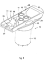
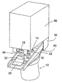
- the separation module 10 of this invention includes a housing 12 for a filter construction such as a pleated filter, a depth filter, hollow fibers or the like. Ports 14,16 and 18 fit over mating fittings 15, 17 and 19 (Fig. 4). Housing 66 (Fig. 5) which contains a feed pump and a dispense pump such as that disclosed in U.S. Patent 5,263,069. Port 14 can be an inlet for fluid to be filtered. Port 16 can be an outlet for retentate. Port 18 can be an outlet for filtered fluid directed to a point of use.
- the separation module 10 includes a pivot surface 20 which extends substantially the complete width of the separation module 10 and two flanges 22 (one shown) which are positioned on opposing surfaces of the separation module 10 and which are attached to walls 24 and 26.
- the separation module 10 is provided with a latch 31 having a vertical arm 32, a hook 33 and a lever 35.
- the latch 31 is secured to the separator module 10 such as by being molded with the walls of slot 37.
- the slot 37 permits movement of latch 31 when a force is applied to lever 35, such as manual force.
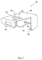
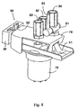
- the stationary receptor 36 includes a top surface 38 having holes 40, 42 and 44 through which fittings 15,17 and 19 (Fig. 4) from a manifold extend.
- the stationary receptor 36 includes a flange 46 having an opening 47 which cooperates with vertical arm 32 and hook 33 of latch 31.
- the stationary receptor 36 also includes shelves 50 and 52 onto which flanges 22 of separation module 10 slide, as well as receptor pivot surface 54 onto which pivot surface 20 fits.
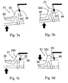
- the latch 31 in its initial position is shown in Fig. 3a.
- a force in the direction of the arrow causes hook 33 to move away from flange 46.
- the latch 31 is moved upwardly by moving filtrate module 10 upwardly so that hook 33 fits onto flange 46.
- This latch position fixes the filtration module 10 to stationary module 36.
- the hook 33 is removed from flange 46 by applying a force to lever 35 as shown by the arrow.
- separation module 10 can be removed from stationary receptor 36.
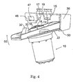
- separation module 10 is slid into stationary receptor 36 onto slides 50 and 52 until pivot line 20 is positioned on pivot surface 54.
- ports 14, 16 and 18 are positioned to fit over fittings 15, 17 and 19 when separation module 10 is rotated upwardly as indicated by arrow 55.
- arm 32 is locked onto flange 46 and hook 33 extends through opening 47. This, in turn, locks separation module 10 into stationary receptor 36 so that leak-free fluid transfer can be affected between ports 14, 16 and 18 and fittings 15, 17 and 19.
- the stationary receptor 36 is attached to a pump housing 66 containing one or a plurality of pumps in a manner well known in the art.
- the fittings 14, 16 and 18 are sealed to mating fittings such as described above.
- the separation module 10 can be provided with a latch 28 comprising two arms 30 and 31.
- Arm 31 is provided with lip 34 which cooperates with the bracket of Fig. 2 as described below.
- the arms 30 and 31 are sufficiently flexible so that the arm 31 can be pushed by arm 30, which in turn, is pushed manually sequentially in order to engage or remove arm 31 from contact with flange 46 of bracket 36 and thereby to permit removal of separation module 10 from bracket 36.
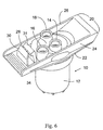
- FIG.7 An alternative embodiment of a separation module of this invention is shown in Fig.7.
- the separation module 10a having ports 14a, 16a, and 18a also is provided with two shelves 22 and a pivot line 20 in the manner described above with reference to Fig. 1.
- the latch 70 includes a lip 72 and an arm 74.
- the lip 72 is configured to fit into a stationary receptor and the lever 74 permits application of manual force in order to remove lip 72 from the stationary receptor thereby to install and remove the separation module 10a from the stationary receptor in the manner described above with reference to Figs. 3a -3d.
- FIG. 8 an embodiment of this invention is illustrated which comprises a portable unit of a separation module 76 and the stationary receptor 78 that is portable.
- the separation module 76 and stationary receptor 78 are joined by latch 31 in the manner described above with reference to Figs. 3a-3d.
- the stationary receptor 78 is provided with fittings 80, 82 and 84 which can be mated with a pumping apparatus (not shown).
- the stationary receptor 78 is joined to a mounting 88 that can be mounted to a wall 90 by a latch 92.
- This embodiment facilitates installation of stationary receptor 78.
- the stationary receptor 78 can include a valve 81 having a manually activated apparatus lever 83 for opening or closing the valve 81 to permit or prevent fluid transfer through fittings.
Claims (11)
- Système comprenant un module de séparation (10a, 76) et un récepteur fixe (36, 78) dans lequel le module de séparation est configuré de façon à être verrouillé et déverrouillé depuis le récepteur, le module comprenant :et le récepteur comprendun logement (12) ;une entrée (14a) et une sortie (18a) de fluide indépendantes l'une de l'autre et situées sur une extrémité du logement ;un élément de séparation à l'intérieur du logement en communication de fluide avec l'entrée et la sortie ;des rebords (22) ;une surface de pivot (20) ; etun verrou (31, 70) fixé audit logement,
une entrée (15) et une sortie (19) complémentaires ;
une surface de pivot (54) ;
une ouverture (47) destinée à recevoir le verrou (31) du module dans la position verrouillée ; et
des surfaces (50, 52) positionnées de façon à supporter les rebords (22) du module lorsque le module est coulissé dans le récepteur afin d'amener la surface de pivot (20) du module en contact avec la surface de pivot (54) du récepteur avant de faire pivoter le module dans la position verrouillée, position dans laquelle lesdites entrée et sortie du module sont en communication de fluide étanche respectivement avec lesdites entrée et sortie complémentaires du récepteur. - Système selon la revendication 1, comprenant en outre un levier (35, 74) auquel une force peut être appliquée afin de déplacer ledit verrou dudit module de séparation.
- Système selon la revendication 1, dans lequel l'entrée et la sortie de fluide du module de séparation sont parallèles.
- Système selon la revendication 1, dans lequel le verrou est moulé sur le logement du module de séparation.
- Système selon la revendication 1, dans lequel ledit module de séparation comprend en outre un troisième connecteur de fluide (16, 16a).
- Système selon la revendication 5, dans lequel le troisième connecteur de fluide est un conduit de ventilation.
- Système selon la revendication 5, dans lequel le troisième connecteur de fluide est parallèle à l'entrée et la sortie du module de séparation.
- Système selon la revendication 5, dans lequel le récepteur comprend en outre un troisième connecteur de fluide (17) complémentaire au troisième connecteur de fluide sur le module de séparation.
- Système selon la revendication 1, dans lequel l'ouverture du récepteur comprend une fente (47) configurée de façon à recevoir le verrou (31) du module de séparation, la structure définissant la fente étant en outre configurée de façon à supporter le module de séparation lorsqu'il est verrouillé sur le récepteur.
- Système selon la revendication 9, dans lequel le récepteur est fixé à un appareil de pompage (66).
- Système selon la revendication 9, dans lequel le récepteur comprend en outre une monture (88) configurée de façon à être fixée de façon coulissante à une paroi.
Priority Applications (1)
| Application Number | Priority Date | Filing Date | Title |
|---|---|---|---|
| EP05077429A EP1637206B1 (fr) | 2001-09-13 | 2002-09-13 | Module de séparation |
Applications Claiming Priority (3)
| Application Number | Priority Date | Filing Date | Title |
|---|---|---|---|
| US32200201P | 2001-09-13 | 2001-09-13 | |
| US332002P | 2001-09-13 | ||
| PCT/US2002/029107 WO2003022388A2 (fr) | 2001-09-13 | 2002-09-13 | Module de separation |
Related Child Applications (1)
| Application Number | Title | Priority Date | Filing Date |
|---|---|---|---|
| EP05077429A Division EP1637206B1 (fr) | 2001-09-13 | 2002-09-13 | Module de séparation |
Publications (3)
| Publication Number | Publication Date |
|---|---|
| EP1448928A2 EP1448928A2 (fr) | 2004-08-25 |
| EP1448928A4 EP1448928A4 (fr) | 2004-10-20 |
| EP1448928B1 true EP1448928B1 (fr) | 2005-12-28 |
Family
ID=34192884
Family Applications (1)
| Application Number | Title | Priority Date | Filing Date |
|---|---|---|---|
| EP02759668A Expired - Lifetime EP1448928B1 (fr) | 2001-09-13 | 2002-09-13 | Module de separation |
Country Status (6)
| Country | Link |
|---|---|
| US (1) | US7163237B2 (fr) |
| EP (1) | EP1448928B1 (fr) |
| JP (1) | JP4731811B2 (fr) |
| CN (1) | CN1327157C (fr) |
| TW (1) | TW558448B (fr) |
| WO (1) | WO2003022388A2 (fr) |
Families Citing this family (23)
| Publication number | Priority date | Publication date | Assignee | Title |
|---|---|---|---|---|
| US6378907B1 (en) | 1996-07-12 | 2002-04-30 | Mykrolis Corporation | Connector apparatus and system including connector apparatus |
| DE60140326D1 (de) * | 2000-05-12 | 2009-12-10 | Pall Corp | Filter |
| EP1322395B1 (fr) * | 2000-09-13 | 2011-02-23 | Entegris, Inc. | Appareil de filtration de liquides |
| US7469932B2 (en) * | 2001-09-13 | 2008-12-30 | Entegris, Inc. | Receptor for a separation module |
| FR2845081B1 (fr) * | 2002-09-26 | 2006-04-28 | Millipore Corp | Ensemble a module de traitement de fluide et structure de support ayant des surfaces fonctionnelles cooperantes perfectionnees, ainsi que module et appareil correspondants |
| DE102004022625A1 (de) * | 2004-05-07 | 2005-12-08 | Robert Bosch Gmbh | Flüssigkeitsfilter |
| EP2089322B1 (fr) * | 2006-11-07 | 2010-09-15 | Koninklijke Philips Electronics N.V. | Dispositif de purification d'eau |
| TWI563351B (en) | 2010-10-20 | 2016-12-21 | Entegris Inc | Method and system for pump priming |
| SG11201401179PA (en) | 2011-10-03 | 2014-04-28 | Entegris Inc | Modular filtration system |
| CN104039415A (zh) * | 2011-12-14 | 2014-09-10 | 3M创新有限公司 | 滤水装置 |
| US9061225B2 (en) * | 2012-03-15 | 2015-06-23 | Kx Technologies Llc | Reinforced receiver for cassette filter locking clip |
| CN104822438A (zh) | 2012-10-01 | 2015-08-05 | 恩特格里斯公司 | 净化系统 |
| US9719504B2 (en) | 2013-03-15 | 2017-08-01 | Integrated Designs, L.P. | Pump having an automated gas removal and fluid recovery system and method |
| US10046263B2 (en) * | 2014-04-04 | 2018-08-14 | Cummins Filtration Ip, Inc. | Snap in place natural gas filter |
| JP2014195807A (ja) * | 2014-06-18 | 2014-10-16 | 株式会社ロキテクノ | フィルターモジュール脱着装置および濾過ユニット |
| DE102014017537B4 (de) | 2014-11-26 | 2019-07-04 | Sartorius Lab Instruments Gmbh & Co. Kg | Verbindungsstruktur zum Verbinden eines Filtergehäuses mit einer Filtergehäusehaltestruktur, Reinigungssystem und Verfahren zum Verbinden eines Filtergehäusedeckels mit einer Filtergehäusehaltestruktur |
| CN106039816B (zh) | 2015-04-09 | 2020-07-03 | 碧然德有限公司 | 用于形成液体处理设备的装置以及液体处理设备 |
| JP2016055290A (ja) * | 2016-01-29 | 2016-04-21 | 株式会社ロキテクノ | フィルターモジュール脱着装置 |
| TWI796406B (zh) * | 2017-12-22 | 2023-03-21 | 澳洲商比利澳洲私人有限公司 | 濾芯架及連接/斷接一濾芯的方法 |
| US20190257457A1 (en) * | 2018-02-21 | 2019-08-22 | Andrew H. Hoenhause | Seed Cart Coupler System |
| USD968558S1 (en) * | 2019-01-11 | 2022-11-01 | Qingdao Ecopure Filter Co., Ltd | Filter unit |
| USD961042S1 (en) * | 2019-01-11 | 2022-08-16 | Qingdao Ecopure Filter Co., Ltd | Filter unit |
| USD973837S1 (en) * | 2019-02-22 | 2022-12-27 | Qingdao Ecopure Filter Co., Ltd | Filter unit |
Family Cites Families (154)
| Publication number | Priority date | Publication date | Assignee | Title |
|---|---|---|---|---|
| US490065A (en) * | 1893-01-17 | Breech-loading firearm | ||
| US136631A (en) | 1873-03-11 | Improvement in steam-power-brake couplings | ||
| US420209A (en) | 1890-01-28 | Pipe-coupling for railway-cars | ||
| US468390A (en) | 1892-02-09 | Low-water alarm | ||
| US898214A (en) | 1903-11-27 | 1908-09-08 | Edward E Gold | Automatic pipe-coupling for railway-cars. |
| US872174A (en) | 1907-03-25 | 1907-11-26 | Ralph M Fyock | Automatic train-pipe coupling. |
| US891718A (en) | 1907-06-21 | 1908-06-23 | Thomas B Mcmillan | Coupling. |
| US872707A (en) | 1907-06-29 | 1907-12-03 | Peter Beahm | Automatic connector for train-pipes. |
| US940334A (en) | 1909-01-11 | 1909-11-16 | William D Leftwich | Coupling mechanism. |
| US967516A (en) | 1909-09-01 | 1910-08-16 | Henry Cain J | Automatic air-coupling. |
| US1070110A (en) | 1912-04-27 | 1913-08-12 | James A Tate | Automatic air-brake coupling or connector. |
| US1186068A (en) | 1915-10-30 | 1916-06-06 | Warren C Benjamin | Air-brake coupling. |
| US1221682A (en) | 1916-04-20 | 1917-04-03 | William C Coffield | Air-coupling. |
| US1389012A (en) | 1920-07-10 | 1921-08-30 | John W Roberts | Pipe-coupling for railway rolling-stock |
| US1786066A (en) | 1928-09-12 | 1930-12-23 | Cobb Connector Company | Train-pipe coupler |
| US1886398A (en) | 1931-08-13 | 1932-11-08 | Arthur C Harrell | Automatic train pipe coupling |
| US2997180A (en) | 1957-06-03 | 1961-08-22 | Chrysler Corp | Anti-vapor-lock fuel filter |
| US3107601A (en) | 1958-09-02 | 1963-10-22 | Richard L Longmire | Filtration and recirculation system for deep fat cooking apparatus |
| US3052863A (en) | 1961-03-16 | 1962-09-04 | Ibm | Contact connector operating devices |
| US3214195A (en) | 1962-05-25 | 1965-10-26 | Crawford Fitting Co | Coupling device for interconnecting multiple fluid lines |
| US3399776A (en) | 1965-09-02 | 1968-09-03 | Robert R. Knuth | Detachable snap-on filter for a hydraulic system |
| DE1525925A1 (de) | 1966-09-16 | 1970-01-22 | Vickers Zimmer Ag | Flanschverbindung,insbesondere fuer Doppelrohrleitungen |
| US3469863A (en) | 1967-04-05 | 1969-09-30 | Trico Products Corp | Fluid coupling assembly |
| US3493115A (en) | 1968-01-29 | 1970-02-03 | Ultra Tech Corp | Cam lock cartridge system |
| US3519133A (en) | 1968-07-09 | 1970-07-07 | Dover Corp | Fluid filter means |
| US3560377A (en) | 1969-01-21 | 1971-02-02 | Amicon Corp | Apparatus and process for filtering fluids |
| US3706184A (en) | 1969-06-09 | 1972-12-19 | Matter Mfg Corp | Wall-recessed suction cleaner |
| US3734851A (en) | 1969-12-29 | 1973-05-22 | K Matsumura | Method and device for purifying blood |
| US3628662A (en) | 1970-03-26 | 1971-12-21 | Marvel Eng Co | Filter antidrain valve assembly |
| US3947080A (en) | 1971-06-14 | 1976-03-30 | Underwriters Safety Device Co. | Quick-connect-disconnect terminal block assembly |
| BE791684A (fr) | 1971-11-22 | 1973-03-16 | Ogden Hubert S | Cartouche filtrante amovible |
| US3802564A (en) | 1972-06-09 | 1974-04-09 | W Turman | Oil filter and adapter |
| US3812659A (en) | 1972-08-02 | 1974-05-28 | Whirlpool Co | Canister vacuum cleaner latching means |
| US3935106A (en) | 1974-01-23 | 1976-01-27 | Lipner Herbert D | Water filter assembly |
| US3950251A (en) | 1974-03-25 | 1976-04-13 | Rayne International | Filter with quick-connect coupling |
| US4089549A (en) | 1976-10-21 | 1978-05-16 | Stratoflex, Inc. | Simultaneous plural fluid conductor connections |
| US4174231A (en) | 1977-09-08 | 1979-11-13 | Hobgood Harold G | Method for flushing the crankcase of an internal combustion engine |
| NO140919C (no) | 1978-04-17 | 1979-12-12 | Helge Dybvig | Anordning ved drivstoffsystem, saerlig for baater |
| DE2852685A1 (de) * | 1978-12-06 | 1980-06-19 | Wabco Fahrzeugbremsen Gmbh | Einrichtung mit grundplatten fuer eine ventilbatterie |
| US4298358A (en) | 1979-01-11 | 1981-11-03 | Baxter Travenol Laboratories, Inc. | Gas separating and venting filter |
| DE3005408A1 (de) | 1979-02-15 | 1980-08-21 | Daicel Chem | Semipermeables membranelement |
| US4283284A (en) | 1979-07-18 | 1981-08-11 | Baxter Travenol Laboratories, Inc. | Hollow fiber dialyzer end seal system |
| US4321911A (en) | 1979-08-15 | 1982-03-30 | Offutt Worthington W | Modular solar collector system |
| US4344777A (en) | 1980-01-07 | 1982-08-17 | Siposs George G | Directed flow bubble trap for arterial blood |
| US4629563B1 (en) | 1980-03-14 | 1997-06-03 | Memtec North America | Asymmetric membranes |
| US4529512A (en) | 1981-01-19 | 1985-07-16 | Clark Equipment Company | Hydraulic reservoir |
| DE3280289D1 (de) | 1981-02-23 | 1991-02-14 | Nippon Denso Co | Filterelement fuer fluidumreinigungssysteme. |
| US4404103A (en) | 1981-11-05 | 1983-09-13 | Drath Edwin H | Rocking swivel hose connectors and method |
| US4416775A (en) | 1981-12-14 | 1983-11-22 | Std Filter Company, Inc. | In-line filter and cartridge therefor |
| US4411783A (en) | 1981-12-23 | 1983-10-25 | Shiley Incorporated | Arterial blood filter with improved gas venting |
| US4524807A (en) | 1982-05-21 | 1985-06-25 | Humphrey Products Company | Snap-together modular manifold construction |
| US4494775A (en) | 1982-09-30 | 1985-01-22 | William Nash Company, Inc. | Fluid coupling |
| US4555130A (en) | 1983-04-01 | 1985-11-26 | The United States Of America As Represented By The Secretary Of The Navy | Diver's umbilical quick-disconnect device |
| NL8301870A (nl) | 1983-05-26 | 1984-12-17 | Wavin Bv | Afdichting voor een inrichting voor het zuiveren van vloeistoffen door membraanfiltratie. |
| US4535997A (en) | 1983-06-24 | 1985-08-20 | Brust John E | Sealing system |
| US4522717A (en) | 1983-06-24 | 1985-06-11 | Brust John E | Filter apparatus |
| DE3327431A1 (de) | 1983-07-29 | 1985-02-14 | Wilhelm 2000 Hamburg Heine | Vorrichtung zum filtern und trennen von stroemungsmedien, insbesondere zur wasserentsalzung und wasserreinigung durch umkehrosmose und ultrafiltration |
| EP0138060B1 (fr) | 1983-09-16 | 1990-03-07 | Mitsubishi Rayon Co., Ltd. | Module de filtrage de fibre creuse et dispositif de purification d'eau utilisant celui-ci |
| US4610781A (en) | 1983-12-30 | 1986-09-09 | Baxter Travenol Laboratories, Inc. | Fluid processing system with flow control manifold |
| US4879032A (en) | 1984-06-04 | 1989-11-07 | Allied Resin Corporation | Fluid separatory devices having improved potting and adhesive compositions |
| US4559136A (en) | 1984-08-31 | 1985-12-17 | Vortex Innerspace Products, Inc. | Aquarium filtering system |
| DE3519060A1 (de) | 1985-05-28 | 1986-12-04 | Robert Dipl.-Ing. Dr. 3352 Einbeck Kohlheb | Trennzelle fuer die druckfiltration und umkehrosmose |
| US4654142A (en) | 1985-11-18 | 1987-03-31 | Everpure, Inc. | Filtering system |
| US4735716A (en) | 1986-01-27 | 1988-04-05 | Cuno Corporated | Quick-change filter cartridge and head therefor |
| USRE34050E (en) | 1986-03-07 | 1992-09-01 | Everpure, Inc. | Filtering system |
| US4719012A (en) | 1986-05-30 | 1988-01-12 | Caterpillar Inc. | Twist on disposable filter |
| US4820174A (en) | 1986-08-06 | 1989-04-11 | Amp Incorporated | Modular connector assembly and filtered insert therefor |
| US4664420A (en) | 1986-09-02 | 1987-05-12 | Island Rubber & Equipment Co., Inc. | Pneumatic self-sealing female coupling incorporating combination locking tumblers |
| US4870961A (en) | 1986-09-22 | 1989-10-03 | Barnard Gordon D | Medical ventilator tube and manifold assembly |
| US4759571A (en) | 1986-10-31 | 1988-07-26 | D. W. Zimmerman Mfg., Inc. | Fluid transfer module with multiple flow paths |
| DE3640531C1 (de) * | 1986-11-27 | 1987-09-03 | Bayerische Motoren Werke Ag | Filteranordnung zum Reinigen von fluessigen Betriebsstoffen,insbesondere des Schmieroeles von Brennkraftmaschinen |
| US4900449A (en) | 1987-05-20 | 1990-02-13 | Gelman Sciences | Filtration membranes and method of making the same |
| US4806240A (en) | 1987-06-12 | 1989-02-21 | Cuno, Incorporated | Adapter and cartridge assembly |
| US4846800A (en) | 1987-10-14 | 1989-07-11 | Kenneth Ouriel | Two chambered autotransfuser device and method of use |
| US4904382A (en) | 1987-11-23 | 1990-02-27 | Everpure, Inc. | Filter cartridge security for locking between operating and non-operating positions |
| DE3740418A1 (de) | 1987-11-28 | 1989-06-08 | Joachim Wolf | Filtervorrichtung |
| US4966699A (en) | 1988-05-25 | 1990-10-30 | Terumo Kabushiki Kaisha | Hollow fiber membrane fluid processor |
| US5057131A (en) | 1988-09-26 | 1991-10-15 | The Scott Fetzer Company | Vacuum cleaner filter bag assembly |
| US4857189A (en) * | 1988-10-13 | 1989-08-15 | Everpure, Inc. | Filter cartridge with a lugged concentric closure portion |
| US4900065A (en) | 1988-10-31 | 1990-02-13 | Dlh Industries, Inc. | Quick-connect fluid coupling |
| DE3837423A1 (de) | 1988-11-04 | 1990-05-10 | Bosch Gmbh Robert | Fluessigkeitsfilter |
| US5167837A (en) * | 1989-03-28 | 1992-12-01 | Fas-Technologies, Inc. | Filtering and dispensing system with independently activated pumps in series |
| NL8901090A (nl) | 1989-04-28 | 1990-11-16 | X Flow Bv | Werkwijze voor het vervaardigen van een microporeus membraan en een dergelijk membraan. |
| US4932987A (en) | 1989-05-25 | 1990-06-12 | Jorge Molina | Extra corporeal air eliminator |
| US4964984A (en) | 1989-06-14 | 1990-10-23 | Electromedics, Inc. | Blood filter |
| US5167814A (en) | 1989-06-15 | 1992-12-01 | Cuno, Incorporated | Filter apparatus snap lock cartridge retainer |
| JPH0347271A (ja) * | 1989-07-14 | 1991-02-28 | Terumo Corp | 液体処理器 |
| DK162191C (da) | 1989-09-15 | 1992-02-17 | Eskofot As | Filter til filtrering af vaesker |
| US4944776A (en) | 1989-10-05 | 1990-07-31 | Andrew Corporation | Dehumidifier for waveguide system |
| US5221473A (en) * | 1989-10-13 | 1993-06-22 | Burrows Bruce D | Filter cartridge assembly for a reverse osmosis purification system |
| YU212089A (en) | 1989-11-06 | 1992-05-28 | Lazarevic Bogdan | Pipeline for gas under high pressure |
| US5133858A (en) | 1989-11-30 | 1992-07-28 | Layton Manufacturing Corporation | Reverse osmosis water purification apparatus |
| US5139668A (en) | 1989-12-27 | 1992-08-18 | Alberta Research Corporation | Hollow fiber bundle element |
| US5041220A (en) | 1990-01-09 | 1991-08-20 | Minntech Corporation | Hollow fiber filter cartridge for a standarized housing |
| US5022986A (en) | 1990-01-11 | 1991-06-11 | John Lang | Manifold and disposable filter assembly |
| FR2658080A1 (fr) | 1990-02-09 | 1991-08-16 | Hospal Ind | Appareil a fibres creuses. |
| US5108598A (en) | 1990-02-14 | 1992-04-28 | Ultra Flow, Inc. | Horizontal motion quick-disconnect filter system with recirculating bypass |
| AU635414B2 (en) | 1990-04-18 | 1993-03-18 | Terumo Kabushiki Kaisha | Hollow fiber type liquid processing apparatus |
| US5069780A (en) | 1990-06-04 | 1991-12-03 | Infinitex | Ultrafiltration device and process |
| US5362406A (en) * | 1990-07-27 | 1994-11-08 | Pall Corporation | Leucocyte depleting filter device and method of use |
| US5066391A (en) | 1990-08-22 | 1991-11-19 | Faria Manuel S | Reusable liquid filter assembly |
| JP2907235B2 (ja) | 1990-12-15 | 1999-06-21 | 矢崎総業株式会社 | レバー付コネクタ |
| US5096230A (en) | 1991-03-20 | 1992-03-17 | General Resource Corporation | Quick release adapter for connecting an exhaust removal hose to a vehicle tail pipe using magnets |
| EP0522493B2 (fr) * | 1991-07-09 | 2001-10-24 | FASTER S.r.l. | Raccord rapide pour la connection et déconnection simultanée de plusieurs connections d'accouplements et/ou prises, en particulier bloc de connection pour ensemble d'outils sur des véhicules |
| US5160042A (en) | 1991-11-05 | 1992-11-03 | Praxair Technology, Inc. | Double ended hollow fiber bundle and fluids separation apparatus |
| JP3144858B2 (ja) * | 1991-11-06 | 2001-03-12 | 株式会社ロキテクノ | 精密膜プリーッ式フイルターカートリッジの製造方法 |
| WO1993014858A1 (fr) * | 1992-01-22 | 1993-08-05 | Allied-Signal Inc. | Filtre pour liquides a connexion/deconnexion rapide |
| US5180490A (en) * | 1992-01-31 | 1993-01-19 | Baldwin Filters, Inc. | Lubricant filter assembly with internal bypass lock-out |
| JP3373597B2 (ja) * | 1992-06-18 | 2003-02-04 | スタナダイン・オートモーティヴ・コーポレイション | 内部ベントを有する燃料フィルタ |
| US5178758A (en) | 1992-06-30 | 1993-01-12 | Hwang Ching F | Biochemical water filter |
| DE4228155C1 (de) * | 1992-08-25 | 1993-12-02 | Daimler Benz Ag | Vorrichtung zur Befestigung mindestens einer freiliegenden Leitung an einem Befestigungskörper, insbesondere Kraftstoffilter für eine Brennkraftmaschine |
| US5399263A (en) * | 1992-09-24 | 1995-03-21 | Barnstead Thermolyne | Water purifier |
| US5324483B1 (en) * | 1992-10-08 | 1996-09-24 | Warner Lambert Co | Apparatus for multiple simultaneous synthesis |
| US5320752A (en) * | 1992-11-03 | 1994-06-14 | Clack Corporation | Water purification system employing modular flat filter assembly |
| US5401401A (en) * | 1993-01-13 | 1995-03-28 | Aquaria Inc. | Hang on tank canister filter |
| US5336406A (en) * | 1993-01-26 | 1994-08-09 | Elkay Manufacturing Company | Replaceable filter cartridge and head assembly with safety shut-off valve |
| US5380437A (en) * | 1993-02-02 | 1995-01-10 | Biomedical Research And Development Laboratories, Inc. | Multifunctional filtration apparatus |
| US5389260A (en) * | 1993-04-02 | 1995-02-14 | Clack Corporation | Brine seal for tubular filter |
| US5397462A (en) * | 1993-08-24 | 1995-03-14 | Matsushita Electric Industrial Co., Ltd. | Filter with laterally removable element and valve means |
| DE4340218C1 (de) * | 1993-11-25 | 1994-09-22 | Enderle Guenther Dipl Ing Fh | Filtervorrichtung |
| US5484527A (en) * | 1993-12-13 | 1996-01-16 | Stanadyne Automotive Corp. | Module for filter assembly base |
| US5387339A (en) * | 1993-12-17 | 1995-02-07 | Coors Brewing Company | High efficiency liquid filtration system and method for using the same |
| US5417459A (en) * | 1994-02-24 | 1995-05-23 | Sonsub, Inc. | Subsea umbilical connector |
| US5632894A (en) * | 1994-06-24 | 1997-05-27 | Gish Biomedical, Inc. | Arterial blood filter with upwardly inclining delivery inlet conduit |
| CN1120520A (zh) * | 1994-07-08 | 1996-04-17 | 三星电子株式会社 | 净水器的过滤装置 |
| US5462675A (en) * | 1994-07-15 | 1995-10-31 | Pall Corporation | Filter assembly and method of reducing hold-up in a filter assembly |
| US5549010A (en) * | 1995-01-13 | 1996-08-27 | Ziba Design, Inc. | Readily serviceable ancillary fluid filtration system having visual flow rate indicator and quick-release fluid hose fitting |
| US5507530A (en) * | 1995-05-08 | 1996-04-16 | Soo Tractor Sweeprake Company | Plural male and female fluid coupler connecting mechanism and method |
| US5685894A (en) * | 1995-09-13 | 1997-11-11 | Electrolux Corporation | Filter and accessory mount for upright vacuum cleaner exhaust port |
| US6387271B1 (en) * | 1995-09-14 | 2002-05-14 | Pall Corporation | Method for separating solid particulates from a liquid |
| US6059318A (en) * | 1996-04-30 | 2000-05-09 | E. I. Du Pont De Nemours And Company | Lateral entry remotely operated coupling system |
| US5762789A (en) * | 1996-06-28 | 1998-06-09 | Millipore Corporation | Disposable membrane module with low-dead volume |
| US6378907B1 (en) * | 1996-07-12 | 2002-04-30 | Mykrolis Corporation | Connector apparatus and system including connector apparatus |
| US6068770A (en) * | 1996-07-12 | 2000-05-30 | Millipore Corporation | Disposable separation module with quick connect capability |
| US5858224A (en) * | 1997-03-18 | 1999-01-12 | Nelson Industries, Inc. | Filter with pressure sensor mounted in housing end |
| US6048454A (en) * | 1997-03-18 | 2000-04-11 | Jenkins; Dan | Oil filter pack and assembly |
| US5911879A (en) * | 1997-09-24 | 1999-06-15 | Eaton Corporation | Refrigerant filter/drier |
| US6024229A (en) * | 1998-02-27 | 2000-02-15 | Ayers; William R. | Reusable filter assembly |
| US6523861B1 (en) * | 1998-05-26 | 2003-02-25 | Gary Clancy | Fluid coupling and method of use |
| US6059797A (en) * | 1998-06-17 | 2000-05-09 | Ensurg, Inc. | Self-disposing ligating band dispenser |
| USD423081S (en) * | 1998-07-10 | 2000-04-18 | Millipore Corporation | Connector |
| DE69942511D1 (de) * | 1998-10-09 | 2010-07-29 | Entegris Inc | Filtrationsmodul |
| FR2788561B1 (fr) * | 1999-01-14 | 2001-02-16 | Snecma | Circuit de carburant a filtre principal protege |
| US6302147B1 (en) * | 1999-04-08 | 2001-10-16 | Joseph Lorney Rose | Automatic dry release valve coupling |
| US6176904B1 (en) * | 1999-07-02 | 2001-01-23 | Brij M. Gupta | Blood filter |
| US6447023B1 (en) * | 2000-01-27 | 2002-09-10 | Paccar Inc | Air management apparatus and method having manifold and pass-through components |
| DE60144447D1 (de) * | 2000-03-01 | 2011-05-26 | Entegris Inc | Wegwerf-Fluidtrenneinrichtung und Verteilersystem mit leichter Austauschmöglichkeit |
| US20020060189A1 (en) * | 2000-11-22 | 2002-05-23 | Wayne Conrad | Method and apparatus for controlling a household water purifier |
| US6902671B2 (en) * | 2000-12-01 | 2005-06-07 | Millipore Corporation | Chemical process system with multi-functional barrier filter |
| US6443498B1 (en) * | 2001-01-22 | 2002-09-03 | Aerospace Industrial Development Co., Ltd. | Joint engagement device for two multi-joint mechanisms |
| JP2002273113A (ja) * | 2001-03-15 | 2002-09-24 | Koganei Corp | 濾過器および薬液供給装置並びに薬液供給方法 |
| US6752159B1 (en) * | 2001-08-21 | 2004-06-22 | Motorvac Technologies, Inc. | Dynamic oil flusher cleaning system |
| US6581974B1 (en) * | 2001-09-29 | 2003-06-24 | Ragner Manufacturing, Llc | Pivot adaptor attachment for vacuum cleaners |
| FR2835585B1 (fr) * | 2002-02-04 | 2004-03-05 | Staubli Sa Ets | Raccord rapide pour la jonction amovible de deux canalisations |
-
2002
- 2002-09-13 WO PCT/US2002/029107 patent/WO2003022388A2/fr active IP Right Grant
- 2002-09-13 US US10/489,587 patent/US7163237B2/en not_active Expired - Fee Related
- 2002-09-13 TW TW091120983A patent/TW558448B/zh not_active IP Right Cessation
- 2002-09-13 CN CNB028180658A patent/CN1327157C/zh not_active Expired - Fee Related
- 2002-09-13 EP EP02759668A patent/EP1448928B1/fr not_active Expired - Lifetime
- 2002-09-13 JP JP2003526512A patent/JP4731811B2/ja not_active Expired - Fee Related
Also Published As
| Publication number | Publication date |
|---|---|
| JP4731811B2 (ja) | 2011-07-27 |
| WO2003022388A2 (fr) | 2003-03-20 |
| CN1327157C (zh) | 2007-07-18 |
| JP2005501704A (ja) | 2005-01-20 |
| EP1448928A4 (fr) | 2004-10-20 |
| US7163237B2 (en) | 2007-01-16 |
| TW558448B (en) | 2003-10-21 |
| WO2003022388A3 (fr) | 2004-06-24 |
| US20040189002A1 (en) | 2004-09-30 |
| EP1448928A2 (fr) | 2004-08-25 |
| WO2003022388A8 (fr) | 2004-08-12 |
| CN1568412A (zh) | 2005-01-19 |
Similar Documents
| Publication | Publication Date | Title |
|---|---|---|
| EP1448928B1 (fr) | Module de separation | |
| EP1096991B2 (fr) | Procédé de purification d'un système de distribution de fluide, un appareil pont permettant de remplacer un module de séparation et un système de distribution de fluide comprenant cet appareil pont | |
| EP0818228B1 (fr) | Système comprenant un module jetable de séparation de fluide et support avec aptitude à connexion rapide | |
| CN1283342C (zh) | 滤芯和过滤模块 | |
| US7469932B2 (en) | Receptor for a separation module | |
| JP2003525113A (ja) | 交換容易機能を持つ使い捨て流体分離装置−マニホールドアッセンブリ設計 | |
| US20040159600A1 (en) | Filtration module including unitary filter cartridge-bowl construction | |
| EP1637206B1 (fr) | Module de séparation | |
| JP2004535291A (ja) | 一体形フィルタカートリッジ・ボール構造を含む濾過モジュール | |
| KR100919569B1 (ko) | 분리 모듈 |
Legal Events
| Date | Code | Title | Description |
|---|---|---|---|
| PUAI | Public reference made under article 153(3) epc to a published international application that has entered the european phase |
Free format text: ORIGINAL CODE: 0009012 |
|
| 17P | Request for examination filed |
Effective date: 20040313 |
|
| AK | Designated contracting states |
Kind code of ref document: A2 Designated state(s): AT BE BG CH CY CZ DE DK EE ES FI FR GB GR IE IT LI LU MC NL PT SE SK TR |
|
| AX | Request for extension of the european patent |
Extension state: AL LT LV MK RO SI |
|
| A4 | Supplementary search report drawn up and despatched |
Effective date: 20040902 |
|
| RIC1 | Information provided on ipc code assigned before grant |
Ipc: 7B 01D 35/30 A |
|
| 17Q | First examination report despatched |
Effective date: 20041206 |
|
| GRAP | Despatch of communication of intention to grant a patent |
Free format text: ORIGINAL CODE: EPIDOSNIGR1 |
|
| RBV | Designated contracting states (corrected) |
Designated state(s): DE FR GB IT NL |
|
| RAP1 | Party data changed (applicant data changed or rights of an application transferred) |
Owner name: MYKROLIS CORPORATION |
|
| GRAS | Grant fee paid |
Free format text: ORIGINAL CODE: EPIDOSNIGR3 |
|
| GRAA | (expected) grant |
Free format text: ORIGINAL CODE: 0009210 |
|
| AK | Designated contracting states |
Kind code of ref document: B1 Designated state(s): DE FR GB IT NL |
|
| REG | Reference to a national code |
Ref country code: GB Ref legal event code: FG4D |
|
| REF | Corresponds to: |
Ref document number: 60208437 Country of ref document: DE Date of ref document: 20060202 Kind code of ref document: P |
|
| RAP2 | Party data changed (patent owner data changed or rights of a patent transferred) |
Owner name: ENTEGRIS, INC. |
|
| NLT2 | Nl: modifications (of names), taken from the european patent patent bulletin |
Owner name: ENTEGRIS, INC. Effective date: 20060222 |
|
| NLXE | Nl: other communications concerning ep-patents (part 3 heading xe) |
Free format text: PAT. BUL. 04/2006: CORR.: ENTEGRIS INC. |
|
| ET | Fr: translation filed | ||
| PLBE | No opposition filed within time limit |
Free format text: ORIGINAL CODE: 0009261 |
|
| STAA | Information on the status of an ep patent application or granted ep patent |
Free format text: STATUS: NO OPPOSITION FILED WITHIN TIME LIMIT |
|
| 26N | No opposition filed |
Effective date: 20060929 |
|
| PG25 | Lapsed in a contracting state [announced via postgrant information from national office to epo] |
Ref country code: NL Free format text: LAPSE BECAUSE OF NON-PAYMENT OF DUE FEES Effective date: 20070401 |
|
| NLV4 | Nl: lapsed or anulled due to non-payment of the annual fee |
Effective date: 20070401 |
|
| REG | Reference to a national code |
Ref country code: FR Ref legal event code: CA Ref country code: FR Ref legal event code: TP |
|
| PGFP | Annual fee paid to national office [announced via postgrant information from national office to epo] |
Ref country code: DE Payment date: 20100929 Year of fee payment: 9 |
|
| PGFP | Annual fee paid to national office [announced via postgrant information from national office to epo] |
Ref country code: GB Payment date: 20110926 Year of fee payment: 10 Ref country code: FR Payment date: 20111005 Year of fee payment: 10 |
|
| PGFP | Annual fee paid to national office [announced via postgrant information from national office to epo] |
Ref country code: IT Payment date: 20110927 Year of fee payment: 10 |
|
| GBPC | Gb: european patent ceased through non-payment of renewal fee |
Effective date: 20120913 |
|
| REG | Reference to a national code |
Ref country code: FR Ref legal event code: ST Effective date: 20130531 |
|
| PG25 | Lapsed in a contracting state [announced via postgrant information from national office to epo] |
Ref country code: GB Free format text: LAPSE BECAUSE OF NON-PAYMENT OF DUE FEES Effective date: 20120913 Ref country code: DE Free format text: LAPSE BECAUSE OF NON-PAYMENT OF DUE FEES Effective date: 20130403 |
|
| PG25 | Lapsed in a contracting state [announced via postgrant information from national office to epo] |
Ref country code: FR Free format text: LAPSE BECAUSE OF NON-PAYMENT OF DUE FEES Effective date: 20121001 Ref country code: IT Free format text: LAPSE BECAUSE OF NON-PAYMENT OF DUE FEES Effective date: 20120913 |
|
| REG | Reference to a national code |
Ref country code: DE Ref legal event code: R119 Ref document number: 60208437 Country of ref document: DE Effective date: 20130403 |