EP1447269A1 - Dispositif de mise à l'air libre pour une citerne et citerne équipée dudit dispositif - Google Patents
Dispositif de mise à l'air libre pour une citerne et citerne équipée dudit dispositif Download PDFInfo
- Publication number
- EP1447269A1 EP1447269A1 EP04290358A EP04290358A EP1447269A1 EP 1447269 A1 EP1447269 A1 EP 1447269A1 EP 04290358 A EP04290358 A EP 04290358A EP 04290358 A EP04290358 A EP 04290358A EP 1447269 A1 EP1447269 A1 EP 1447269A1
- Authority
- EP
- European Patent Office
- Prior art keywords
- tank
- venting
- plug
- distal end
- cylinder
- Prior art date
- Legal status (The legal status is an assumption and is not a legal conclusion. Google has not performed a legal analysis and makes no representation as to the accuracy of the status listed.)
- Granted
Links
- 238000013022 venting Methods 0.000 title claims description 18
- 239000000523 sample Substances 0.000 claims description 8
- 239000007788 liquid Substances 0.000 claims description 6
- 238000001514 detection method Methods 0.000 claims description 3
- 238000009423 ventilation Methods 0.000 claims 1
- 230000001629 suppression Effects 0.000 abstract 1
- 239000012530 fluid Substances 0.000 description 11
- 238000004140 cleaning Methods 0.000 description 6
- 238000007789 sealing Methods 0.000 description 3
- 238000005406 washing Methods 0.000 description 3
- 125000006850 spacer group Chemical group 0.000 description 2
- 239000007789 gas Substances 0.000 description 1
- 239000002184 metal Substances 0.000 description 1
- BASFCYQUMIYNBI-UHFFFAOYSA-N platinum Chemical compound [Pt] BASFCYQUMIYNBI-UHFFFAOYSA-N 0.000 description 1
- 238000005086 pumping Methods 0.000 description 1
- 238000011084 recovery Methods 0.000 description 1
- 238000007493 shaping process Methods 0.000 description 1
- 239000002689 soil Substances 0.000 description 1
- 239000007921 spray Substances 0.000 description 1
- 229910001220 stainless steel Inorganic materials 0.000 description 1
- 239000010935 stainless steel Substances 0.000 description 1
- 238000003466 welding Methods 0.000 description 1
Images


Classifications
-
- B—PERFORMING OPERATIONS; TRANSPORTING
- B60—VEHICLES IN GENERAL
- B60P—VEHICLES ADAPTED FOR LOAD TRANSPORTATION OR TO TRANSPORT, TO CARRY, OR TO COMPRISE SPECIAL LOADS OR OBJECTS
- B60P3/00—Vehicles adapted to transport, to carry or to comprise special loads or objects
- B60P3/22—Tank vehicles
- B60P3/224—Tank vehicles comprising auxiliary devices, e.g. for unloading or level indicating
- B60P3/2255—Ventilating arrangements
Definitions
- the present invention relates to the field the venting of tanks.
- the present invention relates more particularly to a venting device for a tank, and in particular a truck tank, semi-trailer or trailer, of the type comprising at least a proximal end connected with the interior of said tank and a distal end which is in the open air.
- tanks are generally provided with a conduit allowing the air in the tank to escape or return when filling the tank or emptying it or even during a wash.
- this venting avoids that an overpressure is formed inside the tank, for example because the gases present warm.
- a major drawback of this kind of device is that dirt can get into the tank by the conduit and come to soil the fluid stored in the tank.
- the ideal would be to be able to close completely the tank, but then there is a risk of overpressure or depression.
- the present invention intends to remedy the disadvantages of the prior art by proposing a venting device which can be opened during the stages of filling, emptying or washing the tank and closed outside the filling stages, emptying or washing, while avoiding overpressure or that a depression may form inside the tank.
- the device according to the invention is of the type described above and it is remarkable, in its widest meaning, in that it involves distal end a tight plug, movable between a closed position and an open position using at least one cylinder.
- Said plug is preferably mounted on a movable lever one end of which is driven by said cylinder.
- Said lever preferably has substantially an L shape.
- Said cylinder is preferably a cylinder of pressure causing the cap to open in the event of overpressure inside the device.
- the distal end of the device is, from preferably oriented substantially perpendicular to the proximal end.
- Said plug preferably comprises on its underside a cover fitted with a seal.
- the venting inside has a ball of projection of liquid allowing the washing of its wall interior.
- the venting device includes a detection probe level giving maximum filling information.
- the present invention also relates to a tank and in particular a tank for a truck, a semi-trailer or trailer, equipped with a setting device the open air according to the invention.
- the present invention allows to vent a tank using a resealable device, simple and easy to install.
- the device for vented when closed, plays the role pressure relief valve and opens when pressure internal is greater than a determined value.
- the device for venting controls the level of fluid inside the tank and can cause, thanks to a level probe, the interruption of pumping of the fluid.
- the device (100) according to the invention, illustrated in FIG. 1, is an air venting device for a tank (2), and in particular a truck tank, semi-trailer or trailer.
- This device is preferably positioned at the rear upper end of the tank.
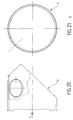
- the device (100) consists of a first cylindrical tube (18), visible in FIGS. 18 and 19, the free end of which forms a proximal end (104) of the device and a second cylindrical tube (19), visible in Figures 20 and 21, the free end of which forms a distal end (106) of the device.
- the two tubes (18, 19) have an identical outside diameter (118), about 133 mm, and an identical thickness of about 4 mm.
- each tube is cut at a right angle.
- These tubes are positioned so that their respective axes are intersecting at 90 ° and are assembled by welding.
- the assembly is completed using a elliptical sheet (20) having a large diameter of 114 mm and a small diameter of 94 mm.
- the proximal end (104) is connected with the interior of said tank (102).
- the tube (18) passes through the insulated rear wall (102) of the tank (102).
- the axis of the tube (18) is substantially horizontal.
- the device (100) has at its end distal (106) a sealed, circular, mobile plug between a closed position and a position opening using at least one cylinder (23).
- the plug (5) is illustrated in closed position with solid lines and open position with dotted lines. In closed position, the cap (5) closes tightly the distal end (106).
- This plug (5) illustrated in FIGS. 12 and 13, has a cup shape with a rim facing the top and showing a return to the bottom.
- the diameter of this plug (5) is greater than the diameter of the tube (19).
- This plug (5) supports a cover (6) circular, visible in Figure 10, with a diameter slightly smaller than the inside diameter of the tube (19), about 120 mm.
- the edge of this cover is not straight but semi-circular, to accommodate a circular seal (27), of O-section, having an internal diameter of the order of 117 mm and a cross-section about 7 mm.
- Figure 4 illustrates a sectional view of the plug (5) closed.
- annular recovery tray drips (21), visible in Figure 1, is positioned the upper end of the tube (19), coaxially with this tube, to allow the fluids to be recovered possibly escaping through the distal end.
- This plate is drilled in one place and present in this place a nozzle (28), in order to allow the fluids to be evacuated escaped.
- the plug (5) is connected to the jack (20) by via an articulation lever (1), illustrated Figure 8.
- This lever substantially square-shaped, has end holes (107, 108), for its fixing respectively to the plug (5) and to the cylinder (23), as well as in its central part a hole central (109).
- Figure 7 illustrates this articulation yoke (7) flat, before shaping.
- the articulation yoke (7) has two holes (71, 72), coaxial when the yoke is U-shaped, in order to allow the introduction of a cylindrical axis (8), surmounted a tubular spacer (9). All these elements each have an axis parallel to the axis (10), so as to ensure that the plug (5) is properly presented horizontally for hermetic sealing of the distal end (106).
- the end of the cylinder rod is provided an end joint yoke (25) having cross section a U shape, to allow slide an axis and rotate the bottom of the lever (1) relative to the distal end of the rod cylinder along the axis (11).
- the central part of the lever (1) is connected to the tube (19) using two support plates (3), illustrated in FIG. 9, identical.
- a cylindrical axis (8 '), surmounted by a tubular spacer (9 ') is positioned between the two parallel support plates (6), in the holes (103), so as to ensure the rotation of the lever (1) along the axis (12), as illustrated in Figure 15.
- Des spacers (14) are positioned in the others holes (105) of the supports (3).
- lever (1) is also illustrated in the closed position by solid lines and in the open position by dotted lines.
- the cylinder (23) is fixed to the device (100) using a substantially identical central articulation yoke (24) to the articulation yoke (7), fixed to the device to using a plate (4), illustrated in FIG. 11.
- This cylinder (23) has a screw (26) at the end of its rod possibly allowing a length adjustment and a sealing adjustment.
- the cylinder (23) has a pressure of operating at 4 bars. It can fire in order to open the cap (5) as soon as the pressure at the cap is greater than about 0.3 bar.
- the device (100) further comprises inside, an internal cleaning system, visible on FIG. 2, using a projection ball (29), located at the end of a distribution pipe (13), illustrated in figures 16 and 17.
- This pipe presents at the opposite end to the projection ball a washer (31) and a thread (32).
- This end is intended to be screwed in a nut (33) to allow it to be fixed on the tube (19).
- This end is further connected to a tip distribution (28 ') and has a tap (34) type quarter turn allowing flow adjustment.
- This internal cleaning system is removable, to allow it to be changed, if necessary, without having to disassemble the device (100) from the tank.
- the device (100) further comprises, at inside, a level detection probe (30).
- This probe is screwed onto a threaded opening (108) provided in the tube (18), as can be seen in the figures 18 and 19.
- This probe is removable, to allow change it, if necessary, without having to disassemble the tank device (100).
- This probe is connected with the system suction of fluids in the tank and allows, when the fluid level reaches a desired value, automatically shut off the suction of fluids, so that the tank does not overflow.
- This probe is located at a height h from the top of the tank of approximately 135 mm, as illustrated in figure 3.
- the proximal end of the tube (18) is completed with a tube (17) of the same diameter and the same thickness, inserted in the wall (102) of the tank (2).
- a seal sealing (16) is positioned between the two tubes (17, 18).
- These two tubes are assembled using screws (35), nuts (36) and washers (37), to allow disassemble, if necessary, the device (100).
- the metal parts of the device (100) is made of stainless steel, in order to meet the criteria for contact food, with the exception of a few parts which are not not in contact with the product stored in the tank.
Landscapes
- Engineering & Computer Science (AREA)
- Health & Medical Sciences (AREA)
- Public Health (AREA)
- Transportation (AREA)
- Mechanical Engineering (AREA)
- Filling Or Discharging Of Gas Storage Vessels (AREA)
- Details Or Accessories Of Spraying Plant Or Apparatus (AREA)
- Nozzles (AREA)
- Devices For Dispensing Beverages (AREA)
- Buildings Adapted To Withstand Abnormal External Influences (AREA)
- Heating, Cooling, Or Curing Plastics Or The Like In General (AREA)
- Pressure Vessels And Lids Thereof (AREA)
- Supply Devices, Intensifiers, Converters, And Telemotors (AREA)
- Loading And Unloading Of Fuel Tanks Or Ships (AREA)
- Quick-Acting Or Multi-Walled Pipe Joints (AREA)
- Devices That Are Associated With Refrigeration Equipment (AREA)
- Confectionery (AREA)
- Feeding And Controlling Fuel (AREA)
Abstract
Description
- la figure 1 illustre une vue en coupe longitudinale du dispositif selon l'invention ;
- la figure 2 illustre une vue de dessus, partielle, du dispositif selon l'invention ;
- la figure 3 illustre une vue avant du dispositif selon l'invention ;
- la figure 4 illustre une vue en coupe selon AA de la figure 1 ;
- la figure 5 illustre une vue en coupe selon BB de la figure 1 ;
- les figures 6 et 7 illustrent respectivement une chape d'articulation pliée et à plat avant pliage ;
- la figure 8 illustre un levier d'articulation ;
- la figure 9 illustre une plaque de support du levier d'articulation ;
- la figure 10 illustre une vue en coupe d'un opercule ;
- la figure 11 illustre une platine de fixation du vérin ;
- les figures 12 et 13 illustrent respectivement une vue en coupe et une vue de dessus d'un bouchon de fermeture de l'extrémité distale du dispositif selon l'invention ;
- la figure 14 illustre une vue en coupe d'un axe de fixation du bouchon sur le levier ;
- la figure 15 illustre une vue en coupe selon CC de la figure 2 ;
- les figures 16 et 17 illustrent un tuyau de distribution interne ;
- les figures 18 et 19 illustrent respectivement une vue de côté et une vue en coupe selon DD de la figure 19 du tube d'extrémité proximale du dispositif selon l'invention ; et
- les figures 20 et 21 illustrent respectivement une vue de côté et une vue selon E de la figure 20 du tube d'extrémité distale du dispositif selon l'invention.
Claims (9)
- Dispositif (100) de mise à l'air libre pour une citerne (2), et notamment une citerne de camion, de semi-remorque ou de remorque, du type comportant au moins une extrémité proximale (104) reliée avec l'intérieur de ladite citerne et une extrémité distale (106) à l'air libre, caractérisé en ce qu'il comporte à son extrémité distale (106) un bouchon étanche (5) mobile entre une position de fermeture et une position d'ouverture à l'aide d'au moins un vérin (23).
- Dispositif (100) de mise à l'air libre selon la revendication 1, caractérisé en ce que ledit bouchon (5) est monté sur un levier (1) mobile dont une extrémité est entraínée par ledit vérin (23).
- Dispositif (100) de mise à l'air libre selon la revendication 2, caractérisé en ce que ledit levier (1) présente sensiblement une forme de L.
- Dispositif (100) de mise à l'air libre selon l'une quelconque des revendications 1 à 3, caractérisé en ce que ledit vérin (23) est un vérin de pression provoquant l'ouverture du bouchon (5) en cas de surpression à l'intérieur du dispositif.
- Dispositif (100) de mise à l'air libre selon l'une quelconque des revendications 1 à 4, caractérisé en ce que l'extrémité distale (106) est orientée sensiblement perpendiculairement à l'extrémité proximale (104).
- Dispositif (100) de mise à l'air libre selon l'une quelconque des revendications 1 à 5, caractérisé en ce que ledit bouchon (5) comporte sur sa face inférieure un opercule (6) équipé d'un joint (27).
- Dispositif (100) de mise à l'air libre selon l'une quelconque des revendications 1 à 6, caractérisé en ce qu'il comporte à l'intérieur une boule de projection de liquide (29).
- Dispositif (100) de mise à l'air libre selon l'une quelconque des revendications 1 à 7, caractérisé en ce qu'il comporte une sonde de détection de niveau (30).
- Citerne (102), et notamment une citerne de camion, de semi-remorque ou de remorque, équipée d'un dispositif (100) de mise à l'air libre selon l'une quelconque des revendications 1 à 8 comportant à son extrémité distale (106) un bouchon étanche (5) mobile entre une position de fermeture et une position d'ouverture à l'aide d'au moins un vérin (23).
Applications Claiming Priority (2)
| Application Number | Priority Date | Filing Date | Title |
|---|---|---|---|
| FR0301679 | 2003-02-12 | ||
| FR0301679A FR2850958B1 (fr) | 2003-02-12 | 2003-02-12 | Dispositif de mise a l'air libre pour une citerne et citerne equipee dudit dispositif |
Publications (2)
| Publication Number | Publication Date |
|---|---|
| EP1447269A1 true EP1447269A1 (fr) | 2004-08-18 |
| EP1447269B1 EP1447269B1 (fr) | 2010-09-29 |
Family
ID=32669352
Family Applications (1)
| Application Number | Title | Priority Date | Filing Date |
|---|---|---|---|
| EP04290358A Expired - Lifetime EP1447269B1 (fr) | 2003-02-12 | 2004-02-11 | Dispositif de mise à l'air libre pour une citerne et citerne équipée dudit dispositif |
Country Status (6)
| Country | Link |
|---|---|
| EP (1) | EP1447269B1 (fr) |
| AT (1) | ATE482848T1 (fr) |
| DE (1) | DE602004029301D1 (fr) |
| FR (1) | FR2850958B1 (fr) |
| PL (1) | PL201391B1 (fr) |
| RU (1) | RU2004103048A (fr) |
Cited By (2)
| Publication number | Priority date | Publication date | Assignee | Title |
|---|---|---|---|---|
| FR2946629A1 (fr) * | 2009-06-15 | 2010-12-17 | Magyar Etablissements | Citerne pourvue d'un event demontable de l'interieur, vehicule citerne et methode d'intervention sur une citerne. |
| US9834128B2 (en) | 2014-04-23 | 2017-12-05 | Tremcar Inc. | Tank trailer operating system |
Families Citing this family (1)
| Publication number | Priority date | Publication date | Assignee | Title |
|---|---|---|---|---|
| FR2899570B1 (fr) * | 2006-04-07 | 2008-06-06 | Magyar Sa Ets | Dispositif de mise a l'air d'une citerne comprenant un bouchon actionne manuellement |
Citations (5)
| Publication number | Priority date | Publication date | Assignee | Title |
|---|---|---|---|---|
| WO1985001034A1 (fr) * | 1983-08-30 | 1985-03-14 | Emco Wheaton U. K. Limited | Assemblages d'event pour conteneurs de fluide |
| DE8803444U1 (de) * | 1988-03-15 | 1988-05-26 | Kieselmann GmbH, 75438 Knittlingen | Tankdom-Armatur |
| DE9318785U1 (de) * | 1993-08-07 | 1994-02-24 | Niehüser, Hermann, Dipl.-Ing., 33449 Langenberg | Be- und Entlüftungsventil für/an Tankfahrzeuge |
| GB2352001A (en) * | 1999-06-12 | 2001-01-17 | Clayton Commercials Ltd | A remotely operated locking lid system |
| US6318402B1 (en) * | 2000-05-25 | 2001-11-20 | Richard Ladeira | Pneumatic tank truck closure apparatus |
-
2003
- 2003-02-12 FR FR0301679A patent/FR2850958B1/fr not_active Expired - Lifetime
-
2004
- 2004-02-04 RU RU2004103048/12A patent/RU2004103048A/ru not_active Application Discontinuation
- 2004-02-11 PL PL365094A patent/PL201391B1/pl not_active IP Right Cessation
- 2004-02-11 AT AT04290358T patent/ATE482848T1/de not_active IP Right Cessation
- 2004-02-11 EP EP04290358A patent/EP1447269B1/fr not_active Expired - Lifetime
- 2004-02-11 DE DE602004029301T patent/DE602004029301D1/de not_active Expired - Lifetime
Patent Citations (5)
| Publication number | Priority date | Publication date | Assignee | Title |
|---|---|---|---|---|
| WO1985001034A1 (fr) * | 1983-08-30 | 1985-03-14 | Emco Wheaton U. K. Limited | Assemblages d'event pour conteneurs de fluide |
| DE8803444U1 (de) * | 1988-03-15 | 1988-05-26 | Kieselmann GmbH, 75438 Knittlingen | Tankdom-Armatur |
| DE9318785U1 (de) * | 1993-08-07 | 1994-02-24 | Niehüser, Hermann, Dipl.-Ing., 33449 Langenberg | Be- und Entlüftungsventil für/an Tankfahrzeuge |
| GB2352001A (en) * | 1999-06-12 | 2001-01-17 | Clayton Commercials Ltd | A remotely operated locking lid system |
| US6318402B1 (en) * | 2000-05-25 | 2001-11-20 | Richard Ladeira | Pneumatic tank truck closure apparatus |
Cited By (4)
| Publication number | Priority date | Publication date | Assignee | Title |
|---|---|---|---|---|
| FR2946629A1 (fr) * | 2009-06-15 | 2010-12-17 | Magyar Etablissements | Citerne pourvue d'un event demontable de l'interieur, vehicule citerne et methode d'intervention sur une citerne. |
| US9834128B2 (en) | 2014-04-23 | 2017-12-05 | Tremcar Inc. | Tank trailer operating system |
| US10562435B2 (en) | 2014-04-23 | 2020-02-18 | Tremcar Inc. | Tank trailer operating system |
| US11014486B2 (en) | 2014-04-23 | 2021-05-25 | Tremcar Inc. | Tank trailer operating system |
Also Published As
| Publication number | Publication date |
|---|---|
| ATE482848T1 (de) | 2010-10-15 |
| PL365094A1 (en) | 2004-08-23 |
| RU2004103048A (ru) | 2005-07-10 |
| FR2850958A1 (fr) | 2004-08-13 |
| DE602004029301D1 (de) | 2010-11-11 |
| FR2850958B1 (fr) | 2006-07-14 |
| PL201391B1 (pl) | 2009-04-30 |
| EP1447269B1 (fr) | 2010-09-29 |
Similar Documents
| Publication | Publication Date | Title |
|---|---|---|
| EP0905084A1 (fr) | Appareil de distribution de liquides, en particulier de boissons | |
| FR2685293A1 (fr) | Dispositif de stockage et de distribution de boisson. | |
| FR2889489A1 (fr) | Soupape de ventilation pour le reservoir a carburant dans des vehicules automobiles. | |
| EP1447269B1 (fr) | Dispositif de mise à l'air libre pour une citerne et citerne équipée dudit dispositif | |
| FR2609482A1 (fr) | Appareil de robinetterie pour le remplissage d'une baignoire | |
| FR2739115A1 (fr) | Conduit de trop-plein exterieur a un appareil sanitaire | |
| FR3121693A1 (fr) | Dispositif d’équipement sanitaire pour cuvette de toilette | |
| FR2568346A1 (fr) | Ventouse pour reseau d'eau sous pression a poussee verticale importante | |
| EP3839161B1 (fr) | Système de rinçage pour cuvette de wc et ensemble cuvette de wc - système de rinçage | |
| EP2142316B1 (fr) | Enceinte de lavage du nez de vidange d'une cuve de stockage et de refroisissement de lait | |
| FR3037118A1 (fr) | ||
| FR2749279A1 (fr) | Dispositif pour maintenir a l'abri de tout contact avec l'atmosphere le vin contenu dans une barique ou tonneau malgre la baisse de niveau due a l'absorption des parois de bois | |
| BE494076A (fr) | ||
| EP2206177B1 (fr) | Dispositif de degazage d'une batterie de vehicule automobile | |
| FR2739169A1 (fr) | Collier de prise en charge pour le branchement d'un abonne sur une canalisation d'alimentation en eau et procede de percement de la canalisation | |
| FR2890617A1 (fr) | Dispositif pour l'evacuation d'eau dans un vehicule automobile | |
| FR2806286A1 (fr) | Machine a laver de type professionnel | |
| EP1842719B1 (fr) | Dispositif de mise à l'air d'une citerne comprenant un bouchon actionné manuellement | |
| EP0325519A1 (fr) | Dispositif pour permettre le fonctionnement dans n'importe quelle position d'une valve de vaporisateur | |
| FR2612810A1 (fr) | Dispositif d'alimentation par gravite pour pistolet de pulverisation de peinture ou de produit analogue | |
| FR2656286A1 (fr) | Dispositif antidepression pour les compartiments d'une citerne routiere. | |
| FR2573504A1 (fr) | Robinet | |
| FR2727740A1 (fr) | Dispositif deversoir pour tube sensiblement vertical, notamment de trop plein | |
| FR3072983A3 (fr) | Siphon avec mise a l'air libre | |
| FR2669903A1 (fr) | Dispositif de vidange pour recipient presentant une ouverture de vidange. |
Legal Events
| Date | Code | Title | Description |
|---|---|---|---|
| PUAI | Public reference made under article 153(3) epc to a published international application that has entered the european phase |
Free format text: ORIGINAL CODE: 0009012 |
|
| AK | Designated contracting states |
Kind code of ref document: A1 Designated state(s): AT BE BG CH CY CZ DE DK EE ES FI FR GB GR HU IE IT LI LU MC NL PT RO SE SI SK TR |
|
| AX | Request for extension of the european patent |
Extension state: AL LT LV MK |
|
| 17P | Request for examination filed |
Effective date: 20041227 |
|
| AKX | Designation fees paid |
Designated state(s): AT BE BG CH CY CZ DE DK EE ES FI FR GB GR HU IE IT LI LU MC NL PT RO SE SI SK TR |
|
| 17Q | First examination report despatched |
Effective date: 20050413 |
|
| GRAP | Despatch of communication of intention to grant a patent |
Free format text: ORIGINAL CODE: EPIDOSNIGR1 |
|
| GRAS | Grant fee paid |
Free format text: ORIGINAL CODE: EPIDOSNIGR3 |
|
| GRAA | (expected) grant |
Free format text: ORIGINAL CODE: 0009210 |
|
| AK | Designated contracting states |
Kind code of ref document: B1 Designated state(s): AT BE BG CH CY CZ DE DK EE ES FI FR GB GR HU IE IT LI LU MC NL PT RO SE SI SK TR |
|
| REG | Reference to a national code |
Ref country code: GB Ref legal event code: FG4D Free format text: NOT ENGLISH |
|
| REG | Reference to a national code |
Ref country code: CH Ref legal event code: EP |
|
| REG | Reference to a national code |
Ref country code: IE Ref legal event code: FG4D Free format text: LANGUAGE OF EP DOCUMENT: FRENCH |
|
| REF | Corresponds to: |
Ref document number: 602004029301 Country of ref document: DE Date of ref document: 20101111 Kind code of ref document: P |
|
| PG25 | Lapsed in a contracting state [announced via postgrant information from national office to epo] |
Ref country code: AT Free format text: LAPSE BECAUSE OF FAILURE TO SUBMIT A TRANSLATION OF THE DESCRIPTION OR TO PAY THE FEE WITHIN THE PRESCRIBED TIME-LIMIT Effective date: 20100929 Ref country code: FI Free format text: LAPSE BECAUSE OF FAILURE TO SUBMIT A TRANSLATION OF THE DESCRIPTION OR TO PAY THE FEE WITHIN THE PRESCRIBED TIME-LIMIT Effective date: 20100929 |
|
| REG | Reference to a national code |
Ref country code: NL Ref legal event code: VDEP Effective date: 20100929 |
|
| PG25 | Lapsed in a contracting state [announced via postgrant information from national office to epo] |
Ref country code: SI Free format text: LAPSE BECAUSE OF FAILURE TO SUBMIT A TRANSLATION OF THE DESCRIPTION OR TO PAY THE FEE WITHIN THE PRESCRIBED TIME-LIMIT Effective date: 20100929 |
|
| PG25 | Lapsed in a contracting state [announced via postgrant information from national office to epo] |
Ref country code: SE Free format text: LAPSE BECAUSE OF FAILURE TO SUBMIT A TRANSLATION OF THE DESCRIPTION OR TO PAY THE FEE WITHIN THE PRESCRIBED TIME-LIMIT Effective date: 20100929 Ref country code: GR Free format text: LAPSE BECAUSE OF FAILURE TO SUBMIT A TRANSLATION OF THE DESCRIPTION OR TO PAY THE FEE WITHIN THE PRESCRIBED TIME-LIMIT Effective date: 20101230 |
|
| REG | Reference to a national code |
Ref country code: IE Ref legal event code: FD4D |
|
| PG25 | Lapsed in a contracting state [announced via postgrant information from national office to epo] |
Ref country code: PT Free format text: LAPSE BECAUSE OF FAILURE TO SUBMIT A TRANSLATION OF THE DESCRIPTION OR TO PAY THE FEE WITHIN THE PRESCRIBED TIME-LIMIT Effective date: 20110131 Ref country code: IT Free format text: LAPSE BECAUSE OF FAILURE TO SUBMIT A TRANSLATION OF THE DESCRIPTION OR TO PAY THE FEE WITHIN THE PRESCRIBED TIME-LIMIT Effective date: 20100929 Ref country code: SK Free format text: LAPSE BECAUSE OF FAILURE TO SUBMIT A TRANSLATION OF THE DESCRIPTION OR TO PAY THE FEE WITHIN THE PRESCRIBED TIME-LIMIT Effective date: 20100929 Ref country code: NL Free format text: LAPSE BECAUSE OF FAILURE TO SUBMIT A TRANSLATION OF THE DESCRIPTION OR TO PAY THE FEE WITHIN THE PRESCRIBED TIME-LIMIT Effective date: 20100929 Ref country code: RO Free format text: LAPSE BECAUSE OF FAILURE TO SUBMIT A TRANSLATION OF THE DESCRIPTION OR TO PAY THE FEE WITHIN THE PRESCRIBED TIME-LIMIT Effective date: 20100929 Ref country code: CZ Free format text: LAPSE BECAUSE OF FAILURE TO SUBMIT A TRANSLATION OF THE DESCRIPTION OR TO PAY THE FEE WITHIN THE PRESCRIBED TIME-LIMIT Effective date: 20100929 Ref country code: EE Free format text: LAPSE BECAUSE OF FAILURE TO SUBMIT A TRANSLATION OF THE DESCRIPTION OR TO PAY THE FEE WITHIN THE PRESCRIBED TIME-LIMIT Effective date: 20100929 |
|
| PG25 | Lapsed in a contracting state [announced via postgrant information from national office to epo] |
Ref country code: ES Free format text: LAPSE BECAUSE OF FAILURE TO SUBMIT A TRANSLATION OF THE DESCRIPTION OR TO PAY THE FEE WITHIN THE PRESCRIBED TIME-LIMIT Effective date: 20110109 Ref country code: IE Free format text: LAPSE BECAUSE OF FAILURE TO SUBMIT A TRANSLATION OF THE DESCRIPTION OR TO PAY THE FEE WITHIN THE PRESCRIBED TIME-LIMIT Effective date: 20100929 |
|
| PLBE | No opposition filed within time limit |
Free format text: ORIGINAL CODE: 0009261 |
|
| STAA | Information on the status of an ep patent application or granted ep patent |
Free format text: STATUS: NO OPPOSITION FILED WITHIN TIME LIMIT |
|
| BERE | Be: lapsed |
Owner name: ETS MAGYAR S.A. Effective date: 20110228 |
|
| PG25 | Lapsed in a contracting state [announced via postgrant information from national office to epo] |
Ref country code: DK Free format text: LAPSE BECAUSE OF FAILURE TO SUBMIT A TRANSLATION OF THE DESCRIPTION OR TO PAY THE FEE WITHIN THE PRESCRIBED TIME-LIMIT Effective date: 20100929 |
|
| 26N | No opposition filed |
Effective date: 20110630 |
|
| PG25 | Lapsed in a contracting state [announced via postgrant information from national office to epo] |
Ref country code: MC Free format text: LAPSE BECAUSE OF NON-PAYMENT OF DUE FEES Effective date: 20110228 |
|
| REG | Reference to a national code |
Ref country code: CH Ref legal event code: PL |
|
| GBPC | Gb: european patent ceased through non-payment of renewal fee |
Effective date: 20110211 |
|
| REG | Reference to a national code |
Ref country code: DE Ref legal event code: R097 Ref document number: 602004029301 Country of ref document: DE Effective date: 20110630 |
|
| PG25 | Lapsed in a contracting state [announced via postgrant information from national office to epo] |
Ref country code: LI Free format text: LAPSE BECAUSE OF NON-PAYMENT OF DUE FEES Effective date: 20110228 Ref country code: CH Free format text: LAPSE BECAUSE OF NON-PAYMENT OF DUE FEES Effective date: 20110228 |
|
| PG25 | Lapsed in a contracting state [announced via postgrant information from national office to epo] |
Ref country code: BE Free format text: LAPSE BECAUSE OF NON-PAYMENT OF DUE FEES Effective date: 20110228 |
|
| REG | Reference to a national code |
Ref country code: DE Ref legal event code: R119 Ref document number: 602004029301 Country of ref document: DE Effective date: 20110901 |
|
| PG25 | Lapsed in a contracting state [announced via postgrant information from national office to epo] |
Ref country code: GB Free format text: LAPSE BECAUSE OF NON-PAYMENT OF DUE FEES Effective date: 20110211 |
|
| PG25 | Lapsed in a contracting state [announced via postgrant information from national office to epo] |
Ref country code: CY Free format text: LAPSE BECAUSE OF FAILURE TO SUBMIT A TRANSLATION OF THE DESCRIPTION OR TO PAY THE FEE WITHIN THE PRESCRIBED TIME-LIMIT Effective date: 20100929 Ref country code: LU Free format text: LAPSE BECAUSE OF NON-PAYMENT OF DUE FEES Effective date: 20110211 |
|
| PG25 | Lapsed in a contracting state [announced via postgrant information from national office to epo] |
Ref country code: DE Free format text: LAPSE BECAUSE OF NON-PAYMENT OF DUE FEES Effective date: 20110901 |
|
| PG25 | Lapsed in a contracting state [announced via postgrant information from national office to epo] |
Ref country code: TR Free format text: LAPSE BECAUSE OF FAILURE TO SUBMIT A TRANSLATION OF THE DESCRIPTION OR TO PAY THE FEE WITHIN THE PRESCRIBED TIME-LIMIT Effective date: 20100929 Ref country code: BG Free format text: LAPSE BECAUSE OF FAILURE TO SUBMIT A TRANSLATION OF THE DESCRIPTION OR TO PAY THE FEE WITHIN THE PRESCRIBED TIME-LIMIT Effective date: 20101229 |
|
| PG25 | Lapsed in a contracting state [announced via postgrant information from national office to epo] |
Ref country code: HU Free format text: LAPSE BECAUSE OF FAILURE TO SUBMIT A TRANSLATION OF THE DESCRIPTION OR TO PAY THE FEE WITHIN THE PRESCRIBED TIME-LIMIT Effective date: 20100929 |
|
| REG | Reference to a national code |
Ref country code: FR Ref legal event code: PLFP Year of fee payment: 13 |
|
| REG | Reference to a national code |
Ref country code: FR Ref legal event code: PLFP Year of fee payment: 14 |
|
| REG | Reference to a national code |
Ref country code: FR Ref legal event code: PLFP Year of fee payment: 15 |
|
| PGFP | Annual fee paid to national office [announced via postgrant information from national office to epo] |
Ref country code: FR Payment date: 20230217 Year of fee payment: 20 |