EP1447036A2 - Vorrichtung zum Erwärmen von Geschirrteilen - Google Patents
Vorrichtung zum Erwärmen von Geschirrteilen Download PDFInfo
- Publication number
- EP1447036A2 EP1447036A2 EP04002814A EP04002814A EP1447036A2 EP 1447036 A2 EP1447036 A2 EP 1447036A2 EP 04002814 A EP04002814 A EP 04002814A EP 04002814 A EP04002814 A EP 04002814A EP 1447036 A2 EP1447036 A2 EP 1447036A2
- Authority
- EP
- European Patent Office
- Prior art keywords
- wall
- air
- cavity
- heating
- plates
- Prior art date
- Legal status (The legal status is an assumption and is not a legal conclusion. Google has not performed a legal analysis and makes no representation as to the accuracy of the status listed.)
- Withdrawn
Links
- 238000010792 warming Methods 0.000 title description 3
- 238000010438 heat treatment Methods 0.000 claims abstract description 34
- 239000011810 insulating material Substances 0.000 claims description 3
- 230000000694 effects Effects 0.000 claims description 2
- 230000005611 electricity Effects 0.000 claims description 2
- 238000005338 heat storage Methods 0.000 claims description 2
- 238000007664 blowing Methods 0.000 claims 1
- 230000001105 regulatory effect Effects 0.000 abstract 1
- 229910001220 stainless steel Inorganic materials 0.000 description 2
- 239000010935 stainless steel Substances 0.000 description 2
- 229910000831 Steel Inorganic materials 0.000 description 1
- XAGFODPZIPBFFR-UHFFFAOYSA-N aluminium Chemical compound [Al] XAGFODPZIPBFFR-UHFFFAOYSA-N 0.000 description 1
- 229910052782 aluminium Inorganic materials 0.000 description 1
- 235000021170 buffet Nutrition 0.000 description 1
- 230000026058 directional locomotion Effects 0.000 description 1
- 235000013305 food Nutrition 0.000 description 1
- 238000009413 insulation Methods 0.000 description 1
- 239000000463 material Substances 0.000 description 1
- 239000010959 steel Substances 0.000 description 1
Images


Classifications
-
- A—HUMAN NECESSITIES
- A47—FURNITURE; DOMESTIC ARTICLES OR APPLIANCES; COFFEE MILLS; SPICE MILLS; SUCTION CLEANERS IN GENERAL
- A47J—KITCHEN EQUIPMENT; COFFEE MILLS; SPICE MILLS; APPARATUS FOR MAKING BEVERAGES
- A47J39/00—Heat-insulated warming chambers; Cupboards with heating arrangements for warming kitchen utensils
- A47J39/02—Dish-warmers; Devices to keep food hot
- A47J39/025—Dish-warmers; Devices to keep food hot for warming dishes without food before use
Definitions
- the invention relates to a device for heating or keeping warm dishes, especially of plates.
- Pre-warmed dishes prevent an unwanted decrease in temperature of the food. Especially with buffets and in the upscale gastronomy, it is desirable that Keep plates warm until shortly before use.
- plate warmers are usually used, which are in the form of a mobile trolley are formed and comprise one or more stack of plates. Controlled by an appropriate Spring device projects in each case a predetermined, independent of the height of the stack Number of plates out of the car and the plates can be there be removed. Inside the car there is a heater, which keeps the plates warm or warms them up until they are in the upper area of the stack and protrude upwards out of the housing.
- Such a device is known for example from DE 28 39 925 C2.
- the stack of dishes are each arranged in a cavity which is enclosed by a cylindrical inner jacket becomes.
- the stack of dishes is heated by a blower, which is in the Air intake openings arranged on the inner jacket suck air from the cavity and then the air heated by a heater again by means of a distribution element in lets the cavity flow in.
- Such devices have several disadvantages. To the some are very bulky and are difficult to transport. These factors prevent use as part of a party service and have a negative impact, if for space reasons or - especially in gourmet restaurants - for aesthetic reasons From the point of view, no fixed trolleys are desired. So that are devices according to DE 28 39 925 C2 not suitable for flexible use at all. In addition, due to the design-related introduction of air at only one point of the inner jacket the dishes are heated to different degrees.
- a more flexible device for heating plates is shown in DE 296 03 212 U1.
- the device comprises a bell-shaped body, which is about to be heated Pieces of crockery is put over, and a heating device is arranged in the upper region thereof that heats the plates from above.
- the use of a fan is also an option mentioned.
- such a device is not for rapid heating of Suitable plates. Even with very high radiant heat, the entire Interior take at least a very long time. On top of that comes out of a stack Several plates only warmed the top slightly while the bottom area the bell hardly heats up.
- the present invention is therefore based on the object of a device for heating of tableware, especially plates, to create that within a short time a large number of plates are evenly heated, take up little space, can be used flexibly is and can be easily transported.
- Such a device for heating and / or keeping warm dishes, in particular Plates has a hood-shaped outer wall, which has a hood interior surrounds in a first cavity suitable for receiving dishes is arranged, which has a preferably cylindrical or frustoconical inner wall is surrounded, wherein the first cavity is surrounded by a second cavity, which at least is partially formed between the inner wall and the outer wall, wherein the first cavity on its upper face via a fan and on its Long sides through air passage openings in the inner wall with the second cavity connected is.
- the device has a heating device which is suitable to heat the air to be circulated inside the hood.
- Such a device can be used flexibly at any time and is easy to transport and also suitable for a short-term warming up of plates, with a variety can be heated quickly and evenly on plates.
- air deflection elements are preferably arranged in the second cavity are suitable, the air blown out by the fan in the direction of the air passage openings to steer in the inner wall, so that the distribution of the heated air still further is optimized.
- the heating device preferably consists of at least one arranged in a ring Heating coil or a heating tube in the second cavity, which provides the advantage that a enormous heating power is emitted evenly, and the heated air on the shortest Path to the air openings in the inner jacket can be performed.
- the device preferably has a base plate which is attached by means of retaining clips the outer wall is detachably connected, the device including plates can be secured and be easily transported.
- a heat storage device is preferably provided which has a heating effect without Ensures power supply, which increases the flexibility of the device.
- the outer wall preferably has a heat insulating material, so that the Heat losses to the outside can be minimized.
- the inner wall and outer wall preferably expand conically downwards, which provides the advantages that the heated air in the second cavity along the wall penetrates particularly well into the lower areas of the device, and several devices can be stacked on top of each other.
- the device advantageously has a heat sensor which switches the power supply to the If necessary, the heating device switches off and thus saves electricity.
- the 1 shows a first embodiment of the device 1 for heating according to the invention or keeping plates warm. It has a hood-shaped outer wall 3 which defines a hood interior and is placed over the plates to be heated can be.
- the outer wall 3 has an outer skin 5, which is preferably made of stainless steel is formed.
- the outer wall 3 can be a layer of heat-insulating Have material 7 to reduce heat loss to the outside.
- an upper insulation is not horizontal on the outer wall 3, but horizontal arranged in the hood interior.
- a this surrounding support ring 8 preferably made of plastic, arranged.
- the plates themselves are received in a first cavity 9, which is surrounded by a cylindrical or frustoconical inner wall 10 is surrounded.
- the inner wall 10 can be made of be made in one piece, but in the embodiment shown consists of four individual Sheets made of aluminum, which also have a circumferential at their upper end Support ring 11 are connected from plastic.
- a second cavity 12 is also arranged in the hood interior. In the preferred In the exemplary embodiment, it has two sections, one arranged in the upper region of the hood Air circulation chamber 13 and a circulating air duct 15, which is located between the side Outer wall 3 and inner wall 10 extends.
- the air duct 15 and thus the second cavity 12 is connected to the first cavity 9 via air passage openings 16, which are formed in the inner wall 10.
- the Air passage openings 16 formed by slots between the sheets of the inner wall 10 arise.
- the ventilator 17 is supplied with mains current by means of a mains plug 19.
- one or more air deflecting elements 20 are provided, which the fan 17 in the circulating air chamber 13 direct air blown in the direction of the circulating air duct 15.
- a hood-shaped plastic element is used as the air deflecting element 20, which is arranged in the upper area of the air circulation chamber 13 and the air in the direction of the air duct 15 conducts radially outwards in all directions.
- the air deflector 20 has a downward tip towards the center, so that in cross section two concave curvatures are visible, which serve to direct the air to the outside.
- a heating device 21 is provided in the circulating air chamber 13, which e.g.
- a heat sensor 25 is provided in the upper region of the circulating air chamber 13 is mounted centrally on the air deflecting element 20.
- a heat controller 27 can on the outer wall 3 be attached.
- the heating of stacked plates with the device according to the invention proceeds as follows from.
- the downwardly open device 1 is like a bell over the put up to a warming stack of plates.
- the air from the first Cavity 9, in which the plates are located sucked into the air circulation chamber 13.
- the above the fan 17 mounted air deflector 20 causes a directional movement of the Air radially outwards, so that the air is heated by the rotating heating coil 21 can be.
- the heated air is conveyed on through the recirculation duct 15 and arrives back into the first cavity 9 via the air passage openings 16 Heat is given off to the plates and the cooled air is returned to the air circulation chamber 13 promoted.
- the heat sensor 25 constantly measures the temperature of the air being transported and switches the power supply when necessary to the heating coil 21. If necessary, the desired temperature can be determined by the Heat controller 27 can be set in advance. Because of the conically widening towards the bottom The shape of the outer wall 3 and inner wall 10 can be multiple devices 1 stacked on top of each other and plugged into each other considerably, which Space requirements during storage or transport are significantly reduced.
- Fig. 2 shows a further variant of the device 1 according to the invention, which also for currentless operation and particularly suitable for use as part of a party service is.
- the embodiments are largely identical. However, are on the air deflector 20 heat accumulator 29 mounted by means of before operating the device on the network the heating coil 21 can be heated to a high temperature. In operation, it can stored heat can be given to the plates without an external power supply.
- the Fan 17 is fed by an accumulator 30, which is also previously on the network has been charged.
- Another aspect of this embodiment provides a base plate 31 on which the plates can be parked before the hood is put over it.
- the bottom plate 31 is preferably insulated and by means of retaining clips 33 with the outer wall mounted overleaf 3 connectable. This makes the device 1 including plates transportable at the top of the hood-shaped outer wall 3 attached handle 35 allows easy carrying of the entire device 1.
- the base plate 31 can be heated itself his.
- a corresponding base plate 31 is of course also in the first embodiment used.
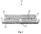
- Fig. 3 shows an alternative bottom plate 31, which is also without mains power Heater can be used.
- On a sub-floor made of heat-insulating Material 37 are heat accumulators 29 arranged laterally from a wall 39 Stainless steel are surrounded. Between the heat accumulators 29 is an annular one Heating coil 21 mounted, a possibly existing heat sensor 25 supplies the temperature in the area of the heat accumulator 29. The air in the hood is, as usual, through the Fan 17 circulates.
- This base plate 31 can be used primarily to keep plates warm replace the heating devices shown above or used in combination with them become.
Landscapes
- Engineering & Computer Science (AREA)
- Food Science & Technology (AREA)
- Devices For Warming Or Keeping Food Or Tableware Hot (AREA)
- Paints Or Removers (AREA)
Abstract
Description
- Fig. 1
- einen Axialschnitt durch eine erste Ausführungsform der erfindungsgemäßen Vorrichtung;
- Fig. 2
- einen Axialschnitt durch eine zweite Ausführungsform der erfindungsgemäßen Vorrichtung; und
- Fig. 3
- einen Schnitt durch eine spezielle Bodenplatte gemäß der Erfindung.
Claims (8)
- Vorrichtung (1) zum Erwärmen und/oder Warmhalten von Geschirrteilen, insbesondere Tellern, mit einer haubenförmigen Außenwandung (3), welche einen Haubeninnenraum umgibt, in dem ein zur Aufnahme von Geschirrteilen geeigneter erster Hohlraum (9) angeordnet ist, der von einer bevorzugt zylinder- oder kegelstumpfförmigen Innenwandung (10) umgeben ist, wobei der erste Hohlraum (9) von einem zweiten Hohlraum (12) umgeben ist, der zumindest teilweise zwischen der Innenwandung (10) und der Außenwandung (3) ausgebildet ist, wobei der erste Hohlraum (9) an seiner oberen Stirnseite über einen Ventilator (17) sowie an seinen Längsseiten über Luftdurchtrittsöffnungen (16) in der Innenwandung (10) mit dem zweiten Hohlraum (12) verbunden ist, und wobei die Vorrichtung (1) eine Heizvorrichtung (21, 29) aufweist, die geeignet ist, die zu zirkulierende Luft im Haubeninnenraum zu erwärmen.
- Vorrichtung (1) nach Anspruch 1, dadurch gekennzeichnet, daß im zweiten Hohlraum (12) mindestens ein Luftablenkelement (20) angeordnet ist, das geeignet ist, die vom Ventilator (17) ausgeblasene Luft in Richtung der Luftdurchtrittsöffnungen (16) in der Innenwandung (10) zu lenken.
- Vorrichtung (1) nach Anspruch 1 oder 2, dadurch gekennzeichnet, daß die Heizvorrichtung als im zweiten Hohlraum (12) angeordnete, ringförmige Heizwendel (21) oder Heizröhre ausgebildet ist.
- Vorrichtung (1) nach einem der vorangehenden Ansprüche, dadurch gekennzeichnet, daß sie eine Bodenplatte (31) aufweist, die mittels Halteklammern (33) mit der Außenwandung (3) lösbar verbunden ist.
- Vorrichtung (1) nach einem der vorangehenden Ansprüche, dadurch gekennzeichnet, daß sie eine Wärmespeichereinrichtung (29) aufweist, die eine Heizwirkung ohne Stromzufuhr gewährleistet.
- Vorrichtung (1) nach einem der vorangehenden Ansprüche, dadurch gekennzeichnet, daß die Außenwandung (3) ein wärmeisolierendes Material (7) aufweist.
- Vorrichtung (1) nach einem der vorangehenden Ansprüche, dadurch gekennzeichnet, daß sich Innenwandung (10) und Außenwandung (3) nach unten hin konisch erweitern.
- Vorrichtung (1) nach einem der vorangehenden Ansprüche, dadurch gekennzeichnet, daß sie einen Wärmesensor (25) aufweist.
Applications Claiming Priority (2)
| Application Number | Priority Date | Filing Date | Title |
|---|---|---|---|
| DE20302352U DE20302352U1 (de) | 2003-02-13 | 2003-02-13 | Vorrichtung zum Erwärmen von Geschirrteilen |
| DE20302352U | 2003-02-13 |
Publications (2)
| Publication Number | Publication Date |
|---|---|
| EP1447036A2 true EP1447036A2 (de) | 2004-08-18 |
| EP1447036A3 EP1447036A3 (de) | 2005-12-21 |
Family
ID=7980029
Family Applications (1)
| Application Number | Title | Priority Date | Filing Date |
|---|---|---|---|
| EP04002814A Withdrawn EP1447036A3 (de) | 2003-02-13 | 2004-02-09 | Vorrichtung zum Erwärmen von Geschirrteilen |
Country Status (2)
| Country | Link |
|---|---|
| EP (1) | EP1447036A3 (de) |
| DE (1) | DE20302352U1 (de) |
Cited By (1)
| Publication number | Priority date | Publication date | Assignee | Title |
|---|---|---|---|---|
| CN107050473A (zh) * | 2017-04-18 | 2017-08-18 | 火星人厨具股份有限公司 | 一种高温烘干杀菌功能碗柜及其作用方法 |
Families Citing this family (2)
| Publication number | Priority date | Publication date | Assignee | Title |
|---|---|---|---|---|
| DE102007024805A1 (de) * | 2007-05-26 | 2008-11-27 | Dietrich Lampe | Mobiler Tellerwärmer |
| DE202009012947U1 (de) | 2009-09-28 | 2010-03-04 | Lampe, Dietrich | Mobiler Tellerwärmer |
Citations (2)
| Publication number | Priority date | Publication date | Assignee | Title |
|---|---|---|---|---|
| DE2839925C2 (de) | 1978-09-14 | 1987-09-03 | Stierlen-Maquet Ag, 7550 Rastatt, De | |
| DE29603212U1 (de) | 1996-02-14 | 1996-04-11 | Beta Engineering S.r.l., Roncadelle, Brescia | Vorrichtung zum Warmhalten, Warmmachen und Auftauen |
Family Cites Families (3)
| Publication number | Priority date | Publication date | Assignee | Title |
|---|---|---|---|---|
| US3538309A (en) * | 1968-10-29 | 1970-11-03 | Bill R Welker | Portable plate heater and carrier |
| DE7923104U1 (de) * | 1979-08-13 | 1980-01-03 | Mkt Moderne Kuechentechnik Gmbh & Co Kg, 7444 Beuren | Vorrichtung zum erwaermen von essgeschirr |
| DE8535894U1 (de) * | 1985-12-20 | 1986-03-20 | Steba Elektrogeräte GmbH & Co KG, 8602 Strullendorf | Tellerwärmer |
-
2003
- 2003-02-13 DE DE20302352U patent/DE20302352U1/de not_active Expired - Lifetime
-
2004
- 2004-02-09 EP EP04002814A patent/EP1447036A3/de not_active Withdrawn
Patent Citations (2)
| Publication number | Priority date | Publication date | Assignee | Title |
|---|---|---|---|---|
| DE2839925C2 (de) | 1978-09-14 | 1987-09-03 | Stierlen-Maquet Ag, 7550 Rastatt, De | |
| DE29603212U1 (de) | 1996-02-14 | 1996-04-11 | Beta Engineering S.r.l., Roncadelle, Brescia | Vorrichtung zum Warmhalten, Warmmachen und Auftauen |
Cited By (1)
| Publication number | Priority date | Publication date | Assignee | Title |
|---|---|---|---|---|
| CN107050473A (zh) * | 2017-04-18 | 2017-08-18 | 火星人厨具股份有限公司 | 一种高温烘干杀菌功能碗柜及其作用方法 |
Also Published As
| Publication number | Publication date |
|---|---|
| EP1447036A3 (de) | 2005-12-21 |
| DE20302352U1 (de) | 2003-05-15 |
Similar Documents
| Publication | Publication Date | Title |
|---|---|---|
| DE2600212C2 (de) | Beheizbare Entnahmevorrichtung für Toastbrote od. dgl. | |
| EP2413739B1 (de) | Tisch zum warmhalten von sich in geschirr befindenden speisen sowie tisch mit einem oder mehreren induktionsmodulen | |
| DE69211611T2 (de) | Kochgerät | |
| DE69734335T2 (de) | Einrichtung zur Sterilisation von Raumluft | |
| EP1138422A2 (de) | Schrumpfgerät für Werkzeuge, insbesondere Hartmetallwerkzeuge | |
| DE1272506B (de) | Elektrischer Herd mit Herdplatte und zumindest einer Back- und Bratroehre | |
| EP2918197B1 (de) | Siebträgeranordnung, Siebträger-Kaffeemaschine und Ableiteinsatz | |
| EP2716190B1 (de) | Vorrichtung zum Warmhalten von Speisen | |
| DE1579508A1 (de) | Geheiztes Tellerausgabegeraet | |
| EP1447036A2 (de) | Vorrichtung zum Erwärmen von Geschirrteilen | |
| DE2649528A1 (de) | Elektroherd fuer den haushaltsgebrauch | |
| DE3006679C2 (de) | Gerät zum elektrischen Beheizen von Rundkolben aus Glas o.dgl. | |
| DE202020106923U1 (de) | Esstisch mit einer Heizeinrichtung | |
| EP0183082A1 (de) | Grilltisch | |
| DE202016002911U1 (de) | Zusatzanordnung für ein pfannenartiges Kochgerät | |
| EP0269892B1 (de) | Vorrichtung zum Warmhalten, insbesondere von Speisen | |
| EP0919174A1 (de) | Wagen zur Aufnahme von mehreren Tabletts mit Speisen | |
| DE202004013093U1 (de) | Speisentransportbehälter | |
| EP3210508B1 (de) | Elektrischer grill | |
| DE2915153C2 (de) | Elektrisch beheizbares Grillgerät | |
| CH684876A5 (de) | Wagen zum Transportieren von Speisen. | |
| WO2011035844A1 (de) | Mobiler tellerwärmer | |
| EP0289635A1 (de) | Elektrisch betriebener Heizlüfter | |
| DE739597C (de) | Elektrische Bratpfanne | |
| DE60320357T2 (de) | Brenner für auf hoher Temperatur zu behandelndes Material |
Legal Events
| Date | Code | Title | Description |
|---|---|---|---|
| PUAI | Public reference made under article 153(3) epc to a published international application that has entered the european phase |
Free format text: ORIGINAL CODE: 0009012 |
|
| AK | Designated contracting states |
Kind code of ref document: A2 Designated state(s): AT BE BG CH CY CZ DE DK EE ES FI FR GB GR HU IE IT LI LU MC NL PT RO SE SI SK TR |
|
| AX | Request for extension of the european patent |
Extension state: AL LT LV MK |
|
| PUAL | Search report despatched |
Free format text: ORIGINAL CODE: 0009013 |
|
| AK | Designated contracting states |
Kind code of ref document: A3 Designated state(s): AT BE BG CH CY CZ DE DK EE ES FI FR GB GR HU IE IT LI LU MC NL PT RO SE SI SK TR |
|
| AX | Request for extension of the european patent |
Extension state: AL LT LV MK |
|
| 17P | Request for examination filed |
Effective date: 20060522 |
|
| AKX | Designation fees paid |
Designated state(s): AT BE BG CH CY CZ DE DK EE ES FI FR GB GR HU IE IT LI LU MC NL PT RO SE SI SK TR |
|
| GRAP | Despatch of communication of intention to grant a patent |
Free format text: ORIGINAL CODE: EPIDOSNIGR1 |
|
| STAA | Information on the status of an ep patent application or granted ep patent |
Free format text: STATUS: THE APPLICATION IS DEEMED TO BE WITHDRAWN |
|
| 18D | Application deemed to be withdrawn |
Effective date: 20080103 |