EP1445433B1 - Commande de soupape d'un moteur à combustion interne controllé par les soupapes - Google Patents
Commande de soupape d'un moteur à combustion interne controllé par les soupapes Download PDFInfo
- Publication number
- EP1445433B1 EP1445433B1 EP04005291A EP04005291A EP1445433B1 EP 1445433 B1 EP1445433 B1 EP 1445433B1 EP 04005291 A EP04005291 A EP 04005291A EP 04005291 A EP04005291 A EP 04005291A EP 1445433 B1 EP1445433 B1 EP 1445433B1
- Authority
- EP
- European Patent Office
- Prior art keywords
- stator
- rotor
- gas exchange
- magnetic
- exchange valve
- Prior art date
- Legal status (The legal status is an assumption and is not a legal conclusion. Google has not performed a legal analysis and makes no representation as to the accuracy of the status listed.)
- Expired - Lifetime
Links
Images


Classifications
-
- H—ELECTRICITY
- H02—GENERATION; CONVERSION OR DISTRIBUTION OF ELECTRIC POWER
- H02K—DYNAMO-ELECTRIC MACHINES
- H02K41/00—Propulsion systems in which a rigid body is moved along a path due to dynamo-electric interaction between the body and a magnetic field travelling along the path
- H02K41/02—Linear motors; Sectional motors
- H02K41/03—Synchronous motors; Motors moving step by step; Reluctance motors
- H02K41/031—Synchronous motors; Motors moving step by step; Reluctance motors of the permanent magnet type
-
- F—MECHANICAL ENGINEERING; LIGHTING; HEATING; WEAPONS; BLASTING
- F01—MACHINES OR ENGINES IN GENERAL; ENGINE PLANTS IN GENERAL; STEAM ENGINES
- F01L—CYCLICALLY OPERATING VALVES FOR MACHINES OR ENGINES
- F01L3/00—Lift-valve, i.e. cut-off apparatus with closure members having at least a component of their opening and closing motion perpendicular to the closing faces; Parts or accessories thereof
- F01L3/20—Shapes or constructions of valve members, not provided for in preceding subgroups of this group
-
- F—MECHANICAL ENGINEERING; LIGHTING; HEATING; WEAPONS; BLASTING
- F01—MACHINES OR ENGINES IN GENERAL; ENGINE PLANTS IN GENERAL; STEAM ENGINES
- F01L—CYCLICALLY OPERATING VALVES FOR MACHINES OR ENGINES
- F01L9/00—Valve-gear or valve arrangements actuated non-mechanically
- F01L9/20—Valve-gear or valve arrangements actuated non-mechanically by electric means
- F01L9/21—Valve-gear or valve arrangements actuated non-mechanically by electric means actuated by solenoids
- F01L2009/2105—Valve-gear or valve arrangements actuated non-mechanically by electric means actuated by solenoids comprising two or more coils
-
- F—MECHANICAL ENGINEERING; LIGHTING; HEATING; WEAPONS; BLASTING
- F01—MACHINES OR ENGINES IN GENERAL; ENGINE PLANTS IN GENERAL; STEAM ENGINES
- F01L—CYCLICALLY OPERATING VALVES FOR MACHINES OR ENGINES
- F01L9/00—Valve-gear or valve arrangements actuated non-mechanically
- F01L9/20—Valve-gear or valve arrangements actuated non-mechanically by electric means
- F01L9/21—Valve-gear or valve arrangements actuated non-mechanically by electric means actuated by solenoids
- F01L2009/2125—Shaft and armature construction
- F01L2009/2126—Arrangements for amplifying the armature stroke
-
- F—MECHANICAL ENGINEERING; LIGHTING; HEATING; WEAPONS; BLASTING
- F01—MACHINES OR ENGINES IN GENERAL; ENGINE PLANTS IN GENERAL; STEAM ENGINES
- F01L—CYCLICALLY OPERATING VALVES FOR MACHINES OR ENGINES
- F01L9/00—Valve-gear or valve arrangements actuated non-mechanically
- F01L9/20—Valve-gear or valve arrangements actuated non-mechanically by electric means
- F01L9/21—Valve-gear or valve arrangements actuated non-mechanically by electric means actuated by solenoids
- F01L2009/2146—Latching means
- F01L2009/2148—Latching means using permanent magnet
-
- F—MECHANICAL ENGINEERING; LIGHTING; HEATING; WEAPONS; BLASTING
- F01—MACHINES OR ENGINES IN GENERAL; ENGINE PLANTS IN GENERAL; STEAM ENGINES
- F01L—CYCLICALLY OPERATING VALVES FOR MACHINES OR ENGINES
- F01L9/00—Valve-gear or valve arrangements actuated non-mechanically
- F01L9/20—Valve-gear or valve arrangements actuated non-mechanically by electric means
- F01L9/21—Valve-gear or valve arrangements actuated non-mechanically by electric means actuated by solenoids
- F01L2009/2167—Sensing means
- F01L2009/2169—Position sensors
-
- F—MECHANICAL ENGINEERING; LIGHTING; HEATING; WEAPONS; BLASTING
- F01—MACHINES OR ENGINES IN GENERAL; ENGINE PLANTS IN GENERAL; STEAM ENGINES
- F01L—CYCLICALLY OPERATING VALVES FOR MACHINES OR ENGINES
- F01L2301/00—Using particular materials
Definitions
- the present invention relates to a gas exchange valve drive for a valve-controlled combustion engine.
- the invention relates to a gas exchange valve, in which the reciprocating motion of the valve member not by a Camshaft is effected and controlled. Rather, in the inventive Gas exchange valve electrically actuates the valve member.
- From DE 195 18 056 A1 is a gas valve control with a gas exchange valve known, which is actuated by a solenoid assembly. It will by a special embodiment of the pole leg of the electromagnet arrangement a related to the movement of the armature signal in the drive line of the electromagnet assembly generated. This signal can be evaluated to any Detect anchor positions without additional sensors.
- a big problem with Use of a solenoid assembly for actuating the valve is the high noise when reaching the respective end positions, the abrupt deceleration when reaching the end positions as well as the required high Holding currents.
- JP-A-3-92518 is a drive device for a valve assembly in Internal combustion engines
- the stator consists of two approximately semi-cylindrical Shells is constructed, both in the circumferential direction and in the longitudinal direction of each Shell shared, the runner facing teeth.
- the individual teeth of each Shell are each surrounded by a coil whose central longitudinal axis in radial Direction runs. This results in a magnetically oriented in the radial direction River, starting from each one of the plurality of teeth, through the Air gap between stand and rotor, flows into the rotor.
- EP 0 485 231 A1 also shows a similar type of design of the stand, the stator coils and the rotor of a drive device for a valve assembly in internal combustion engines. Again, in the radial and tangential direction divided teeth of the stator each surrounded by a radially oriented coil.
- a valve assembly for a valve-controlled Internal combustion engine known, with a traveling electric motor as an actuator for a valve member having a rotor coupled to a valve member and a Stand has.
- the stand is made of sheets whose surface is perpendicular to the Movement direction of the runner is oriented.
- the stand has that as a synchronous or Asynchronous trained runners facing teeth, each one a closed, have the rotor facing cylinder surface. Between each two adjacent teeth of the stator are formed stator coil chambers, in each of which is arranged parallel to the surface of the sheets oriented coil.
- the invention teaches a gas exchange valve drive for a valve-controlled internal combustion engine, with a linear electric motor as an actuator for a valve member, which is defined by the features of claim 1 is.
- the gas exchange valve drive for a valve-controlled Internal combustion engine to be coupled with a valve member hollow cylindrical Runner and a stand, the runner concentrically arranged one above the other, permanent magnetic rings, the stator at least partially made of a soft magnetic Material is constructed and at least one of the runners facing Tooth, the stator has a radially inner lying magnetically conductive region and a radially outer magnetically conductive region, wherein the rings of the rotor between the inner area and the outer Area of the stand are arranged, and the outer area of the stand at least in a section in the radial direction of a C-shaped cross-sectional shape has and has at least one stator coil.
- the concept underlying the invention is that the anchor flooding causing part of the stator, namely the coil area with the Spider coil spatially from the force of the linear motor forming part, namely the tooth area of the stand "herauszuvant".
- This can be compared to conventional Linear motors in which the stator coils each between two teeth are arranged of the stator, achieved a significantly higher anchor flooding become.
- the coil by the inventive design has considerably less spatial restrictions and so on minimal (ohmic) Losses - and associated maximum magnetic field induction - be optimized can. Due to the dimensions of the permanent magnetic rings in the direction of movement of the rotor or the dimensions of a tooth of the stator in the Movement direction of the rotor is defined as a pole pitch, which is smaller than that Dimension of the stator coil in the longitudinal direction.
- the inventive design is in the C-shaped yokes of the outer region of the stator by the stator coil (s) arranged there magnetic flux is induced in the stator and flows from the radial sections the C-shaped yokes over the annular air gap in which the hollow cylindrical Permanent magnets are arranged in the inside (cylindrically shaped) Area of the stand. From the inside area of the stand there The magnetic circle closes again towards the C-shaped yokes of the outside lying area of the stand.
- gas exchange valve drive is that practically only the magnetically active components (the Permanent magnets) contribute to the inertial mass of the rotor, while all other parts of the motor (coils, magnetic return, etc.) associated with the stator. This can be a particularly high ratio of force exerted by the engine to carrier mass can be achieved.
- the gas exchange valve drive according to the invention excellently suited for use in high-speed internal combustion engines to become.
- the approach of the valve member to the end positions (Open or closed position of the gas exchange valve) at high speed done with high acceleration changes, so that the valve member impinges in the valve seat at minimal speed, while the valve member in remaining at very high speeds. It also stands in the end areas of the course of motion the maximum power available. This allows a very low noise and low wear, and because of the achievable high holding forces at the same time very safe operation of the invention in the end positions Gas exchange valves.
- the gas exchange valve drive according to the invention can the total force generated along the stroke of the valve member exactly be set to the required force.
- the gas exchange valve drive according to the invention usually operate in single phase is.
- the stator coils of the individual about each other arranged motors to operate multiphase.
- stator coil Due to the very easy to design (single-phase and cylindrical) arrangement
- the stator coil (s) it is possible, the shaking forces acting on the coil low to keep it, allowing vibration of the coil or friction of the coil on the wall the stator coil chamber are low.
- This makes it possible with minimal insulation material or lining material of the stator coil chamber to get along.
- This also contributes to the compactness and reliability of the overall arrangement.
- Furthermore causes a high power density even with small gas exchange valves, because the fill factor of the stator coil chamber (coil volume in the stator coil chamber based on the total volume of the stator coil chamber) is high.
- the coil area is larger in the direction of movement of the rotor as the distance between two adjacent teeth of the stator.
- the stand can be constructed in known manner from electrical sheet metal parts. However, it is also possible to simplify the production, at least partially as a soft magnetic molded body, preferably made of pressed and / or to make sintered metal powder.
- the stand has a tape roll made of soft magnetic sheet metal strip, wherein at the end faces of the tape roll in each case a soft-magnetic molded body, preferably made of pressed and / or or sintered metal powder is arranged to form the teeth.
- the soft magnetic Shaped body of the stator in its interior with at least one core Cobalt-containing iron, which is preferably designed as a metal coil.
- the runner is a displacement sensor for detection associated with the stroke of the valve member.
- This can be for example an interferometer or an inductive sensor with carrier frequency.
- This is special advantageous because with the actuator according to the invention also partial strokes, (i.e. Intermediate positions between open and closed) of the valve arrangement possible are. This partial stroke can be detected or controlled via the sensor.
- the rotor is at least partially by a magnetic yoke body surrounded by the stand.
- the coil of the stand either on the Stand or be arranged in the return body.
- the magnetically alternately oriented permanent magnet rings can additionally by magnetically non-effective spacers of light material (aluminum, Titanium, plastic - also with glass or carbon fiber inserts, or the like) in one be kept predetermined distance to each other. This allows the inertial mass the runner be kept low.
- light material aluminum, Titanium, plastic - also with glass or carbon fiber inserts, or the like
- the stator is constructed of a soft magnetic material and has teeth facing the runner. Between two adjacent teeth of the stator, a winding chamber may be formed in which a winding is arranged is.
- the rotor has rings of permanent magnetic material. These magnet rings are concentrically arranged one above the other and their magnetic Orientation is designed so that in a predetermined position of the runner two teeth of the stator each with a magnetic ring with opposite magnetic Orientation aligned.
- the stator is at least partially of the runner - separated from each other by an air gap - surrounded.
- Eastern is to form an inner rotor motor of the runner at least partially from surrounded by the stand.
- the stand is also possible according to the invention, the stand to form by superimposed permanent magnet discs, while the rotor a winding chamber which by corresponding soft magnetic Ring discs is limited.
- the runner is at least partially surrounded by a magnetic yoke body.
- each gas exchange valve with at least two winding chambers Provide teeth, windings in the stator and corresponding permanent magnets in the rotor, wherein the windings in the adjacent gas exchange valves in such opposite directions be controlled that the magnetic fluxes through the magnetic return body as little as possible leakage flux shares have.
- the volume - and the weight - of the magnetic yoke body be kept low. In addition, the power losses are minimized.
- the magnetic return body has a shape of a cross section approximately rectangular profile tube, in which two have mutually opposite walls breakthroughs through which the inner part of the stator (coil assemblies) and the rotor protrude.
- This arrangement minimizes the leakage flux and in particular allows a very efficient installation a plurality of juxtaposed such gas exchange valves, wherein - corresponding electrical control required - adjacent gas exchange valve actuators use the magnetic inference at least in part alternately can.
- the mass (and the volume) of the magnetic yoke body be minimized.
- the invention relates to an internal combustion engine with at least a combustion cylinder, with at least one valve arrangement for one or Exhaust valves having one or more of the above features.
- Fig. 1 is a first embodiment of a gas exchange valve drive according to the invention schematically illustrated in longitudinal section.
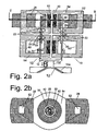
- Fig. 2a is a second embodiment of a gas exchange valve drive according to the invention schematically illustrated in longitudinal section.
- Fig. 2b is a sectional view taken along the line II-II in the embodiment illustrated in FIG. 2a.
- Fig. 3 is a third embodiment of a gas exchange valve drive according to the invention schematically illustrated in longitudinal section.
- Fig. 4 is a fourth embodiment of a gas exchange valve drive according to the invention schematically illustrated in longitudinal section.
- Fig. 5 is a fifth embodiment of a gas exchange valve drive according to the invention partially illustrated schematically in longitudinal section.
- Fig. 6 is a sixth embodiment of a gas exchange valve drive according to the invention partially illustrated schematically in longitudinal section.
- FIG. 1 shows a first embodiment of an electric linear motor 10 illustrated in the valve assembly according to the invention as an actuator for a Valve member 12 of a gas exchange valve, whose associated valve seat 12a only is illustrated schematically.
- the linear motor 10 has one with the valve member 12 via a rod 14 coupled rotor 16 and a stand 18th
- the stator 18 is in this embodiment as a soft magnetic molded body having a substantially hollow cylindrical shape and a therein cylindrical core formed of sintered iron-metal powder.
- the molding functionally in a tooth area 18a and a tooth area 18a adjacent but divided by him coil area 18b divided.
- the tooth portion 18a of the stator 18 has at its periphery two of the rotor 16 facing teeth 22 with a closed lateral surface.
- the individual teeth In the present example with circular in plan view Formkörpem the individual teeth have 22nd a circular cylindrical surface.
- oval shaped bodies or shaped body having a polygonal shape for the construction of the stator 18 to use.
- the two teeth 22 of the stator 18 define between them a parallel to the teeth 22 extending annular groove 24, whose dimension in the present embodiment in the direction of movement B of the rotor 16 of the dimension of the two Teeth 22 corresponds.
- the stator 18 Adjacent to the tooth region 18a, the stator 18 has the coil region 18b, which has an open to the outside stator coil chamber 26, in the arranged a concentric to the central longitudinal axis of the stator 18 stator coil 28 is.
- the stator coil 28 is to achieve the highest possible fill factor than Copper reel executed.
- the type of interconnection of the individual coils 28 and their timed application of electrical current is of the desired Type of motor (single or multi-phase motor) dependent, with a single-phase Operation is easier and therefore preferable.
- each coil 28 over its entire extent in the stator coil chamber 26 is arranged, it also contributes over its entire length to the effective force formation in the linear motor.
- the rotor 16 is a hollow cylinder, the magnetic rings 30 of permanent magnetic material (for example samarium cobalt) has.
- the individual magnetic rings 30 are arranged concentrically one above the other, wherein the magnetic orientation of the magnetic rings is alternately radially oriented and the Rings in their dimensions is designed so that in a predetermined position of the rotor 16 two teeth 22 of a stator 18 each with a magnetic ring 30 with are aligned in the same magnetic orientation.
- Between two consecutive magnet rings 30 can be used to reduce the inertial mass of the rotor 16 also not magnetically effective hollow cylindrical Spacers made of plastic, for example made of carbon fiber reinforced plastic be inserted.
- the abutting permanent magnet rings and the magnetic non-effective hollow cylinder are firmly connected. In other words are located in the moving part of the motor (the rotor) no magnetic flux conducting Parts (for example, flux guide pieces), but only permanent magnets, which are always optimal are arranged in the magnetic field. This arrangement also has the advantage a weight saving.
- radially oriented washers made of permanent magnetic Material can not produce sufficient magnetic field strength is It is also possible according to the invention, ring disk segments of permanent magnets so put together that one directed radially (from inside to outside or vice versa) Magnetic field transverse to the direction of movement of the rotor 16 is formed.
- the distance between the teeth 22 may be compared to the size of the Teeth 22 in the direction of movement B of the rotor 16 vary. However, this requires also corresponding design of the magnetic rings 30 of the rotor 16, since the periodicity the magnetic rings 30 of the rotor 16 equal to the periodicity of the teeth 22 and whose intermediate annular grooves 24 must be on the stand 18.
- a distance encoder 32 is arranged, which with a corresponding Probe 34 is scanned.
- a hollow cylindrical Pipe 40 is provided, which at its one end portion (in Fig. 1 above) two radially having inwardly extending teeth 42 which in the assembled state of the Stand 18 are aligned with the teeth 22 of the stator 18. At its other end closes the hollow cylindrical tube 40 with the outer rim of the coil portion 18b off.
- Fig. 1 two superposed stator 18 are shown, the of a common rotor 16 are penetrated. This makes it possible, if appropriate Actuations of the two coils 28 of the two stator 18 a two-phase To realize linear drive.
- the coils 28 are located on the radially outer side To arrange portion of the magnetic yoke 40. This is related explained with the illustrated in Fig. 2 embodiment below.
- Fig. 2 shows a gas exchange valve drive with a stator 18 and a hollow cylindrical rotor 16, which consists of concentric superimposed permanent magnetic Wrestling 30 is constructed with alternating magnetic orientations.
- the stator 18 is substantially made of a soft magnetic material constructed with a radially inner lying magnetically conductive region 50 and a radially outer lying magnetically conductive region 52.
- the magnetic rings 30th of the rotor are 16 in the air gap between the inner region 50 and the outer region 52 of the stator 18 is arranged.
- the inner region 50 and the outer region 52 each have two aligned with the rotor 16 facing teeth 22 through an annular groove 24 are separated from each other and also each with one of the magnetic rings 30 of the rotor 16 are aligned.
- the inventive arrangement is also with each only one tooth 22 on the inner region 50 and the outer one Area 52 functional, each with one of the magnetic rings 30 of the rotor aligned.
- the arrangement according to the invention also works, if only on at the inside area 50 or the outside area 52 Tooth 22 is formed, which is aligned with one of the magnet rings 30 of the rotor.
- the coil of the stator 18 is greater than the distance or the space between two adjacent arranged teeth 22 of the stator 18th
- FIG. 2 A significant difference between the embodiment of FIG. 1 and the embodiment of FIG. 2 is that in Fig. 2, the stator coil is not only as in Fig. 1, the radially inner region of the stator coaxially surrounds.
- the radially outer region 52 of the stator 18 in two radially opposite sections 54 designed in cross-section C-shaped.
- the C-shaped sections 54 has two in the direction of movement B of the rotor sixteenth spaced apart radially oriented legs 56, 58.
- the respective radial oriented legs 56, 58 are essentially in the direction of movement B the rotor 16 oriented connection yoke 60 connected to each other.
- Each of the Connecting yoke 60 carries a stator coil 28.
- stator coils 28 radially oriented Stand coils on the radial legs 56, 58 provide.
- stator coils 28 are only in the upper Motor unit shown in Fig. 2a, while in the lower motor unit in Fig. 2a are omitted.
- the stator 18 with its radially inner and radially outer regions is a soft magnetic molded body of pressed and sintered metal powder.
- a wound sheet metal core 62 with cobalt-containing iron in the metal powder of the molding in front of the presses and sintering introduced.
- the wound sheet core 62 with cobalt-containing Iron practically completely fill the stand 18 in its inner part, such that between the wound sheet metal core 62 and the stator winding 28th no soft magnetic pressed and sintered metal powder is provided.
- the radially outer part of the stator 18 in the direction of the magnetic flux wound sheet metal cores with cobalt-containing iron be introduced.
- the radially inner region 40 of the Stand 18 also cylindrical with a stator coil 28.
- the magnetic fluxes induced by the stator coils are added together in-phase control.
- Fig. 2b are of the radially outer portion of the stator 18 along the circumference of the stator 18 distributes two sections 54, respectively a stator coil 28 is arranged.
- a stator coil 28 is arranged.
- Fig. 2 is a braking and holding device for the rotor 16 in its lower end position (ie the open position) illustrated.
- This is a the rings 30 of the rotor 16 surrounding or surrounded by these magnetic ring 70th with radial magnetic orientation in the region of a respective stop of the rotor 16 fixed in place.
- the magnetic ring 70 is related to the direction of movement of the rotor 16 and in particular based on the end position of the lower Rings 30 of the rotor 16 is arranged so that the lowest ring 30 of the rotor 16 can completely move past the magnetic ring 70 before the lower Reached stop.
- the magnetic orientation of the magnet ring 70 and the lower Ring 30 of the rotor is chosen so that, for example, both rings magnetic N poles are, which are directed towards each other. It is understood that such Brake and holding device for the rotor 16 also provided at the upper end position can be used and also in the embodiment of FIG. 1 can be used.
- FIG. 3 shows a further embodiment of a gas exchange valve drive according to the invention for a valve-controlled internal combustion engine schematically illustrated in longitudinal section.
- the stator 18 has a hollow cylindrical core in this embodiment Tape roll 18 'of a soft magnetic sheet metal strip, preferably made Iron-cobalt sheet whose surface is parallel to the axis of movement B of the rotor 16th is oriented. At the two end faces of the tape roll 18 'is in each case a soft magnetic Molded body 18 ", 18" 'of sintered iron-metal powder, which project beyond the tape roll 18 'in the radial direction.
- the moldings 18 ", 18 "'of the stand 18 form at its periphery the rotor 16 facing teeth 22nd with a closed lateral surface.
- circular Formkörpem 18 ", 18 ''' have the individual teeth 22 a circular cylindrical Lateral surface.
- oval shaped body 18 ", 18" 'or Shaped body 18 ", 18” 'to be used with polygonal shape for the construction of the stator 18.
- a rod 34 with a etched on its peripheral surface tooth profile, with a Hall probe 36th is scanned.
- the lower end (in the figure) of the rod 34 is connected to the valve member 12 and the rod 14 rigidly coupled, so that the Hall probe 36 a movement of the rod 34 in the direction of movement B can detect.
- the rotor 16 is a hollow cylinder, the Rings 30 of permanent magnetic material (for example samarium cobalt) has.
- the individual permanent magnetic rings 30 are arranged concentrically one above the other, wherein the magnetic orientation of the permanent-magnetic rings 30 (indicated through the center of the pole or away from her directed arrows in each ring) so is designed that in a predetermined position of the rotor 16, two teeth 22 of a Stand 18, each with a ring 30 with opposite magnetic orientation aligned.
- a magnetic ring 30 with a tooth of a first stand for example, the middle
- the second magnetic ring 30 with a tooth of a second stator for example, the lower one
- flees it is also possible that the two magnetic rings 30 with the both teeth of a stand are aligned.
- the rotor 16 is constructed of permanent magnet rings stacked on each other and are firmly connected to each other.
- a magnetic return is a rectangular cross-section magnetic conductive tube 40 provided in two opposite walls Recesses 40a, 40b, through which the rotor 16 and the stator protrude.
- the walls of the tube 32 have such a material thickness and such Distance from each other that they are aligned with two teeth 22 of a stator 18.
- two Magnet rings 30 may be spaced apart.
- at least four magnetic rings 30 are provided, wherein in each case two magnetic rings 30 (ie a magnetic ring pair) with opposite magnetic orientation either lie directly against each other or only a small (axial) distance from each other to have.
- the rotor 16 is a hollow cylinder, the Rings 30 of permanent magnetic material (for example, samarium cobalt) has.
- the individual rings 30 are arranged concentrically one above the other, wherein the magnetic Orientation of the rings (indicated by the center of the stator or by her directed away arrows in each ring) radially oriented and designed so that in a predetermined position of the rotor 16 two teeth 22 of a stator 18, respectively are aligned with a ring 30 of opposite magnetic orientation. It can in particular in the embodiment shown in FIG.
- stator coils a magnetic ring with a tooth of a first stand (for example, the middle) aligned, while the second magnetic ring with a tooth of a second stand (for example, the lower one) is aligned.
- first stand for example, the middle
- second magnetic ring with a tooth of a second stand for example, the lower one
- the two magnet rings with the two teeth of a Stands are aligned.
- rectangular magnetically conductive tube 40 is provided, which in two opposite Wall recesses 42a, 42b, through which the runner 16 and the stand protrude.
- the walls of the tube 40 have such a material thickness and such a distance from each other that they with two teeth 22 of a Stands 18 are aligned.
- Two mutually adjacent stator 18 of a gas exchange valve are through an aluminum rail 44 acting as a spacer and eddy current shield firmly connected.
- two Magnet rings are spaced apart.
- at least four magnetic rings provided, each with two magnetic rings (ie a Magnetic ring pair) with opposite magnetic orientation either directly lie against each other or have only a small (axial) distance from each other.
- the stroke can be influenced. It is between two rings 30 opposite magnetic orientation magnetically non-effective hollow cylinder, for example made of carbon fiber reinforced Plastic arranged, so that in total less magnet rings than stator teeth available. This has the advantage of saving weight, but requires one electrical control with more power.
- the stands are in principle unchanged, however, the axial distance between the tubes 40 is reduced by the spacer 44 has a lower height. Furthermore, the number of Magnetic rings 30 compared to the embodiment of Fig. 1 significantly reduced what a significantly reduced moving mass means. It should be mentioned that the only one magnetic ring per solenoid or stator pole represents the minimum number. In this arrangement, the direction of the magnetic flux is no longer relevant, as long as the magnetic flux is oriented in the radial direction.
- FIG. 6 Another embodiment is shown in Fig. 6, in which the spacers 16a between the magnetic rings 30 are dimensioned so that the middle coil two magnetic rings 30 are assigned during the upper and lower coil in each case only one magnetic ring 30 is assigned.
- the illustrated embodiments are particularly suitable, the required Hub of about 20 mm with the required dynamics in the available to realize a relatively small space.
Landscapes
- Engineering & Computer Science (AREA)
- General Engineering & Computer Science (AREA)
- Physics & Mathematics (AREA)
- Mechanical Engineering (AREA)
- Combustion & Propulsion (AREA)
- Chemical & Material Sciences (AREA)
- Geometry (AREA)
- Electromagnetism (AREA)
- Power Engineering (AREA)
- Valve Device For Special Equipments (AREA)
- Magnetically Actuated Valves (AREA)
- Reciprocating, Oscillating Or Vibrating Motors (AREA)
- Valve-Gear Or Valve Arrangements (AREA)
- Electrically Driven Valve-Operating Means (AREA)
Claims (17)
- Mécanisme d'entraínement pour soupape d'échange de gaz destinée à un moteur à combustion interne commandé par soupapes, comprenant :un induit cylindrique creux (16) destiné à être accouplé à un opercule de soupape (12), et un stator (18), dans lesquelsl'induit (16) comprend des bagues magnétiques permanentes (30) concentriques agencées les unes au-dessus des autres,le stator (18) est réalisé au moins partiellement en un matériau magnétique doux et comporte au moins une région magnétiquement conductrice (50) située radialement à l'intérieur et au moins une région magnétiquement conductrice (52) située radialement à l'extérieur,au moins une dent (22) est réalisée sur la région magnétiquement conductrice (50), située radialement à l'intérieur, du stator (18) et/ou sur la région magnétiquement conductrice (52), située radialement à l'extérieur, du stator (18) dans la direction de déplacement de l'induit (16), dent dont la dimension dans la direction de déplacement de l'induit (16) est essentiellement égale à la dimension d'une bague magnétique permanente (30) dans la direction de déplacement de l'induit (16), de sorte que dans une position prédéterminée de l'induit (16), ladite au moins une dent (22) du stator (18) est alignée avec une bague magnétique permanente (30), etles bagues (30) de l'induit (16) sont agencées entre la région intérieure (50) et la région extérieure (52) du stator (18).
- Mécanisme d'entraínement pour soupape d'échange de gaz selon la revendication 1, dans lequel des bagues magnétiques permanentes (30) voisines, de l'induit (16), comportent des orientations magnétiques orientées radialement et en alternance.
- Mécanisme d'entraínement pour soupape d'échange de gaz selon la revendication 1, dans lequel deux bagues respectives voisines (30) de l'induit (16) sont tenues à une distance prédéterminée l'une de l'autre par des éléments d'écartement magnétiquement sans effet.
- Mécanisme d'entraínement pour soupape d'échange de gaz selon la revendication 1, dans lequel les dimensions des bagues magnétiques permanentes (30) dans la direction de déplacement de l'induit (16) et de ladite au moins une dent (22) du stator (18) définissent une subdivision polaire qui est plus petite que la dimension de la bobine de stator (28) dans sa direction longitudinale.
- Mécanisme d'entraínement pour soupape d'échange de gaz selon la revendication 1, dans lequel la région intérieure (50) du stator (18) comprend une bobine de stator (28) en supplément ou à la place de la région extérieure (52) du stator (18).
- Mécanisme d'entraínement pour soupape d'échange de gaz selon la revendication 4, dans lequel la région de bobine (18b) en direction de déplacement de l'induit (16) est plus grande que la distance entre deux dents voisines (22) du stator (18).
- Mécanisme d'entraínement pour soupape d'échange de gaz selon la revendication 1, dans lequel le stator (18) est un corps conformé magnétique doux, de préférence à partir d'une poudre métallique pressée et/ou frittée.
- Mécanisme d'entraínement pour soupape d'échange de gaz selon la revendication 1, dans lequel le corps conformé magnétique doux du stator (18) comprend à l'intérieur au moins un noyau (62) avec du fer contenant du cobalt.
- Mécanisme d'entraínement pour soupape d'échange de gaz selon la revendication 1, dans lequel ladite au moins une bobine de stator (28) est agencée
dans une région (56, 58), du tronçon partiel (54) réalisé avec une section en forme de C, orientée transversalement à la direction de déplacement (B) de l'induit (16), ou
dans une région (60), du tronçon partiel (54) réalisé avec une section en forme de C, orientée essentiellement parallèlement à la direction de déplacement (B) de l'induit (16), ou
dans une région (50) intérieure du stator (18) orientée essentiellement parallèlement à la direction de déplacement (B) de l'induit (16) de manière à entourer le stator (18) de façon concentrique. - Mécanisme d'entraínement pour soupape d'échange de gaz selon l'une ou l'autre des revendications 1 et 9, dans lequel au moins deux tronçons partiels (54), réalisés avec une section en forme de C et comportant respectivement au moins une bobine de stator (28), sont agencés de façon répartie le long de la périphérie du stator (18).
- Mécanisme d'entraínement pour soupape d'échange de gaz selon la revendication 1, dans lequel un détecteur de course (32, 34, 36) destiné à détecter la course de l'opercule de soupape (12) est associé à l'induit (16).
- Mécanisme d'entraínement pour soupape d'échange de gaz selon la revendication 1, dans lequel, pour freiner et maintenir l'induit (16) dans l'une au moins de ses positions finales, une bague magnétique (70) qui entoure les bagues (30) de l'induit (16) ou qui est entourée par celles-ci et qui présente une orientation magnétique radiale dans la zone de la position finale respective de l'induit (16) est agencée de telle manière qu'avant d'atteindre la position finale, une bague (30) de l'induit (16) présentant la même orientation magnétique que la bague magnétique (70) passe devant celle-ci pour occuper ensuite la position finale.
- Mécanisme d'entraínement pour soupape d'échange de gaz selon la revendication 1, dans lequel l'induit est au moins partiellement entouré par un corps fermant un circuit magnétique (52).
- Mécanisme d'entraínement pour soupape d'échange de gaz selon la revendication 1, dans lequel un corps fermant un circuit magnétique est constitué par un tube magnétiquement conducteur (40) présentant de préférence une section rectangulaire, dans lequel des évidements (40a, 40b) sont prévus dans deux parois mutuellement opposées, à travers lesquels passent l'induit et le stator, lesdites parois ayant une telle épaisseur et présentant une telle distance l'une par rapport à l'autre qu'elles sont alignées avec deux dents (22) d'un stator (18).
- Mécanisme d'entraínement pour soupape d'échange de gaz selon la revendication 10, dans lequel le stator (18) comprend un bobinage (18') réalisé à partir d'une bande en tôle d'un matériau magnétique doux.
- Mécanisme d'entraínement pour soupape d'échange de gaz selon la revendication 1, dans lequel les dents (22), ou respectivement les aimants permanents (20) qui se trouvent à l'opposé de celles-ci, sont dimensionné(e)s, en relation à l'extension axiale de la chambre (26) du bobinage, de telle manière que sur un tronçon de l'induit (18) trouvent place au moins deux autres aimants permanents (20), et dans lequel l'extension axiale du tronçon de l'induit (18) correspond à l'extension axiale des dents (22) et de la chambre (26) du bobinage.
- Moteur à combustion interne comprenant au moins un cylindre de combustion, et comprenant au moins une soupape d'échange de gaz avec les caractéristiques d'une ou de plusieurs des revendications précédentes.
Applications Claiming Priority (7)
| Application Number | Priority Date | Filing Date | Title |
|---|---|---|---|
| DE10035973 | 2000-07-24 | ||
| DE10035973A DE10035973C2 (de) | 2000-07-24 | 2000-07-24 | Gaswechselventil für einen ventilgesteuerten Verbrennungsmotor |
| DE10044789A DE10044789C2 (de) | 2000-09-11 | 2000-09-11 | Antiebsvorrichtung eines Gaswechselventils für einen ventilgesteuerten Verbrennungsmotor |
| DE10044789 | 2000-09-11 | ||
| DE10125767A DE10125767C1 (de) | 2001-05-28 | 2001-05-28 | Gaswechselventilantrieb für einen ventilgesteuerten Verbrennungsmotor |
| DE10125767 | 2001-05-28 | ||
| EP01958014A EP1305505B1 (fr) | 2000-07-24 | 2001-07-24 | Mecanisme de commande de soupapes d'echange gazeux destine a un moteur a combustion interne commande par soupapes |
Related Parent Applications (1)
| Application Number | Title | Priority Date | Filing Date |
|---|---|---|---|
| EP01958014A Division EP1305505B1 (fr) | 2000-07-24 | 2001-07-24 | Mecanisme de commande de soupapes d'echange gazeux destine a un moteur a combustion interne commande par soupapes |
Publications (2)
| Publication Number | Publication Date |
|---|---|
| EP1445433A1 EP1445433A1 (fr) | 2004-08-11 |
| EP1445433B1 true EP1445433B1 (fr) | 2005-06-15 |
Family
ID=27213970
Family Applications (3)
| Application Number | Title | Priority Date | Filing Date |
|---|---|---|---|
| EP01958014A Expired - Lifetime EP1305505B1 (fr) | 2000-07-24 | 2001-07-24 | Mecanisme de commande de soupapes d'echange gazeux destine a un moteur a combustion interne commande par soupapes |
| EP04005291A Expired - Lifetime EP1445433B1 (fr) | 2000-07-24 | 2001-07-24 | Commande de soupape d'un moteur à combustion interne controllé par les soupapes |
| EP04005289A Expired - Lifetime EP1445432B1 (fr) | 2000-07-24 | 2001-07-24 | Commande de soupape d'un moteur à combustion interne controllé par les soupapes |
Family Applications Before (1)
| Application Number | Title | Priority Date | Filing Date |
|---|---|---|---|
| EP01958014A Expired - Lifetime EP1305505B1 (fr) | 2000-07-24 | 2001-07-24 | Mecanisme de commande de soupapes d'echange gazeux destine a un moteur a combustion interne commande par soupapes |
Family Applications After (1)
| Application Number | Title | Priority Date | Filing Date |
|---|---|---|---|
| EP04005289A Expired - Lifetime EP1445432B1 (fr) | 2000-07-24 | 2001-07-24 | Commande de soupape d'un moteur à combustion interne controllé par les soupapes |
Country Status (8)
| Country | Link |
|---|---|
| US (1) | US6755161B2 (fr) |
| EP (3) | EP1305505B1 (fr) |
| JP (1) | JP2004518841A (fr) |
| KR (1) | KR20030065455A (fr) |
| AU (1) | AU2001279781A1 (fr) |
| DE (3) | DE50106559D1 (fr) |
| ES (3) | ES2240489T3 (fr) |
| WO (1) | WO2002008579A1 (fr) |
Families Citing this family (16)
| Publication number | Priority date | Publication date | Assignee | Title |
|---|---|---|---|---|
| DE10303426A1 (de) | 2003-01-29 | 2004-08-19 | Compact Dynamics Gmbh | Elektrisch betätigte Ventilanordnung |
| FR2851289B1 (fr) * | 2003-02-18 | 2007-04-06 | Peugeot Citroen Automobiles Sa | Actionneur electromecanique de soupape pour moteur a combustion interne et moteur a combustion interne muni d'un tel actionneur |
| ATE458129T1 (de) * | 2003-04-26 | 2010-03-15 | Camcon Ltd | Elektromagnetische ventilbetätigungsvorrichtung |
| US20060231783A1 (en) * | 2003-05-26 | 2006-10-19 | Continental Teves Ag & Co. Ohg | Valve drive for a gas exchange valve |
| DE10326911B3 (de) * | 2003-06-14 | 2004-11-11 | Festo Ag & Co | Elektromagnetische Antriebsvorrichtung |
| WO2004113687A1 (fr) * | 2003-06-26 | 2004-12-29 | Continental Teves Ag & Co. Ohg | Mecanisme de commande destine a une soupape de changement des gaz |
| US6951255B2 (en) * | 2003-11-17 | 2005-10-04 | Shepherd John D | Weed extraction tool |
| US7128032B2 (en) * | 2004-03-26 | 2006-10-31 | Bose Corporation | Electromagnetic actuator and control |
| DE102004041618B4 (de) * | 2004-08-27 | 2009-09-03 | Compact Dynamics Gmbh | Startervorrichtung zum Andrehen von Brennkraftmaschinen |
| DE102005017483B4 (de) * | 2005-04-15 | 2007-04-05 | Compact Dynamics Gmbh | Linearaktor in einem Elektro-Schlagwerkzeug |
| DE102005017482B4 (de) * | 2005-04-15 | 2007-05-03 | Compact Dynamics Gmbh | Gaswechselventilaktor für einen ventilgesteuerten Verbrennungsmotor |
| DE102005017481B4 (de) * | 2005-04-15 | 2007-08-30 | Compact Dynamics Gmbh | Linearaktor |
| DE102006013099A1 (de) * | 2005-08-25 | 2007-03-22 | Lsp Innovative Automotive Systems Gmbh | Rotor eines elektromotorischen Ventilantriebs |
| US8795609B2 (en) * | 2007-02-08 | 2014-08-05 | Biokit, S.A. | Magnetic particle washing station |
| US8191857B2 (en) * | 2008-10-09 | 2012-06-05 | Parker-Hannifin Corporation | Linear motor valve |
| EP3719962A1 (fr) | 2019-04-01 | 2020-10-07 | LIM-Tech Limited | Machine électromotrice |
Family Cites Families (12)
| Publication number | Priority date | Publication date | Assignee | Title |
|---|---|---|---|---|
| JP2759330B2 (ja) * | 1988-12-28 | 1998-05-28 | 株式会社いすゞセラミックス研究所 | 電磁力バルブ駆動装置 |
| JP2579207B2 (ja) * | 1988-12-28 | 1997-02-05 | 株式会社いすゞセラミックス研究所 | バルブのステッピング駆動装置 |
| JP2639587B2 (ja) * | 1989-03-30 | 1997-08-13 | 株式会社いすゞセラミックス研究所 | バルブのステッピング駆動装置 |
| JP2596459B2 (ja) * | 1989-03-30 | 1997-04-02 | 株式会社いすゞセラミックス研究所 | バルブの電磁力駆動装置 |
| JP2709742B2 (ja) | 1989-12-20 | 1998-02-04 | 株式会社いすゞセラミックス研究所 | 電磁力バルブ駆動装置 |
| JPH04175408A (ja) * | 1990-11-08 | 1992-06-23 | Isuzu Ceramics Kenkyusho:Kk | 電磁力バルブ駆動装置 |
| JPH05312013A (ja) | 1992-05-01 | 1993-11-22 | Isuzu Motors Ltd | 電磁駆動バルブ |
| DE19518056B4 (de) * | 1995-05-17 | 2005-04-07 | Fev Motorentechnik Gmbh | Einrichtung zur Steuerung der Ankerbewegung einer elektromagnetischen Schaltanordnung und Verfahren zur Ansteuerung |
| DE19723923C2 (de) | 1997-06-06 | 2000-06-21 | Gruendl & Hoffmann | Ventilanordnung für einen ventilgesteuerten Verbrennungsmotor |
| US6176207B1 (en) * | 1997-12-08 | 2001-01-23 | Siemens Corporation | Electronically controlling the landing of an armature in an electromechanical actuator |
| US6039014A (en) | 1998-06-01 | 2000-03-21 | Eaton Corporation | System and method for regenerative electromagnetic engine valve actuation |
| JP3715460B2 (ja) * | 1999-03-31 | 2005-11-09 | 株式会社日立製作所 | 機関弁の電磁駆動装置 |
-
2001
- 2001-07-24 DE DE50106559T patent/DE50106559D1/de not_active Expired - Lifetime
- 2001-07-24 DE DE50106532T patent/DE50106532D1/de not_active Expired - Lifetime
- 2001-07-24 EP EP01958014A patent/EP1305505B1/fr not_active Expired - Lifetime
- 2001-07-24 JP JP2002514043A patent/JP2004518841A/ja active Pending
- 2001-07-24 DE DE50106560T patent/DE50106560D1/de not_active Expired - Lifetime
- 2001-07-24 AU AU2001279781A patent/AU2001279781A1/en not_active Abandoned
- 2001-07-24 ES ES01958014T patent/ES2240489T3/es not_active Expired - Lifetime
- 2001-07-24 EP EP04005291A patent/EP1445433B1/fr not_active Expired - Lifetime
- 2001-07-24 EP EP04005289A patent/EP1445432B1/fr not_active Expired - Lifetime
- 2001-07-24 ES ES04005289T patent/ES2242171T3/es not_active Expired - Lifetime
- 2001-07-24 KR KR10-2003-7001000A patent/KR20030065455A/ko not_active Application Discontinuation
- 2001-07-24 WO PCT/EP2001/008562 patent/WO2002008579A1/fr active IP Right Grant
- 2001-07-24 ES ES04005291T patent/ES2242172T3/es not_active Expired - Lifetime
-
2003
- 2003-01-21 US US10/348,430 patent/US6755161B2/en not_active Expired - Fee Related
Also Published As
| Publication number | Publication date |
|---|---|
| EP1445433A1 (fr) | 2004-08-11 |
| EP1305505B1 (fr) | 2005-06-15 |
| ES2242172T3 (es) | 2005-11-01 |
| US6755161B2 (en) | 2004-06-29 |
| EP1305505A1 (fr) | 2003-05-02 |
| KR20030065455A (ko) | 2003-08-06 |
| DE50106560D1 (de) | 2005-07-21 |
| WO2002008579A1 (fr) | 2002-01-31 |
| DE50106532D1 (de) | 2005-07-21 |
| AU2001279781A1 (en) | 2002-02-05 |
| JP2004518841A (ja) | 2004-06-24 |
| EP1445432B1 (fr) | 2005-06-15 |
| DE50106559D1 (de) | 2005-07-21 |
| ES2242171T3 (es) | 2005-11-01 |
| ES2240489T3 (es) | 2005-10-16 |
| US20030111029A1 (en) | 2003-06-19 |
| EP1445432A1 (fr) | 2004-08-11 |
Similar Documents
| Publication | Publication Date | Title |
|---|---|---|
| EP1445433B1 (fr) | Commande de soupape d'un moteur à combustion interne controllé par les soupapes | |
| DE69309444T2 (de) | Bürstenloser gleichstrommotor/-generator | |
| DE69218470T2 (de) | Stator und Rotor aufweisende, scheibenförmige Maschine mit hohem Wirkungsgrad und kleiner Reaktanz | |
| EP0450288B1 (fr) | Moteur électrique linéaire | |
| WO2006034974A1 (fr) | Moteur linéaire à flux transversal de type polygone | |
| DE4300440C2 (de) | Elektrische Transversalflußmaschine mit ringförmigen Wicklungssträngen | |
| DE10146123A1 (de) | Elektronisch kommutierter Elektromotor mit achsparallelen Spulen | |
| EP0986696B1 (fr) | Dispositif a soupapes pour moteur a combustion interne a commande par soupapes | |
| DE3880255T2 (de) | Elektrische Maschine insbesondere mit radialen Luftspalten. | |
| DE10125767C1 (de) | Gaswechselventilantrieb für einen ventilgesteuerten Verbrennungsmotor | |
| EP1263122A1 (fr) | Entrainement lineaire à symétrie rotative avec un ensemble actionneur double-face | |
| EP1869756B1 (fr) | Actionneur lineaire | |
| DE102005017482B4 (de) | Gaswechselventilaktor für einen ventilgesteuerten Verbrennungsmotor | |
| DE10044789C2 (de) | Antiebsvorrichtung eines Gaswechselventils für einen ventilgesteuerten Verbrennungsmotor | |
| DE10360713A1 (de) | Elektromagnetischer Linearaktuator | |
| EP2507894B1 (fr) | Machine électrique excitée par des aimants permanents | |
| DE19848123C1 (de) | Transversalflußmaschine mit Rotor-Sammler | |
| DE68906612T2 (de) | Kraftmotor. | |
| DE10035973C2 (de) | Gaswechselventil für einen ventilgesteuerten Verbrennungsmotor | |
| DE10031349A1 (de) | Elementbauweise bei TFM | |
| DE19723924A1 (de) | Linearmotor | |
| DE20206108U1 (de) | Elektromechanischer Energiewandler | |
| DE4215011A1 (de) | Elektromagnetischer verstellantrieb | |
| WO2006076900A1 (fr) | Actionneur lineaire | |
| WO2000053899A1 (fr) | Moteur a combustion interne comportant au moins un systeme de soupapes de commande |
Legal Events
| Date | Code | Title | Description |
|---|---|---|---|
| PUAI | Public reference made under article 153(3) epc to a published international application that has entered the european phase |
Free format text: ORIGINAL CODE: 0009012 |
|
| AC | Divisional application: reference to earlier application |
Ref document number: 1305505 Country of ref document: EP Kind code of ref document: P |
|
| AK | Designated contracting states |
Kind code of ref document: A1 Designated state(s): DE ES FR GB IT SE |
|
| 17P | Request for examination filed |
Effective date: 20041013 |
|
| GRAP | Despatch of communication of intention to grant a patent |
Free format text: ORIGINAL CODE: EPIDOSNIGR1 |
|
| GRAS | Grant fee paid |
Free format text: ORIGINAL CODE: EPIDOSNIGR3 |
|
| GRAA | (expected) grant |
Free format text: ORIGINAL CODE: 0009210 |
|
| AKX | Designation fees paid |
Designated state(s): DE ES FR GB IT SE |
|
| AC | Divisional application: reference to earlier application |
Ref document number: 1305505 Country of ref document: EP Kind code of ref document: P |
|
| AK | Designated contracting states |
Kind code of ref document: B1 Designated state(s): DE ES FR GB IT SE |
|
| REG | Reference to a national code |
Ref country code: GB Ref legal event code: FG4D Free format text: NOT ENGLISH |
|
| PGFP | Annual fee paid to national office [announced via postgrant information from national office to epo] |
Ref country code: GB Payment date: 20050621 Year of fee payment: 5 |
|
| REG | Reference to a national code |
Ref country code: SE Ref legal event code: TRGR |
|
| PGFP | Annual fee paid to national office [announced via postgrant information from national office to epo] |
Ref country code: ES Payment date: 20050720 Year of fee payment: 5 Ref country code: SE Payment date: 20050720 Year of fee payment: 5 |
|
| REF | Corresponds to: |
Ref document number: 50106560 Country of ref document: DE Date of ref document: 20050721 Kind code of ref document: P |
|
| GBT | Gb: translation of ep patent filed (gb section 77(6)(a)/1977) |
Effective date: 20050725 |
|
| REG | Reference to a national code |
Ref country code: ES Ref legal event code: FG2A Ref document number: 2242172 Country of ref document: ES Kind code of ref document: T3 |
|
| ET | Fr: translation filed | ||
| PLBE | No opposition filed within time limit |
Free format text: ORIGINAL CODE: 0009261 |
|
| STAA | Information on the status of an ep patent application or granted ep patent |
Free format text: STATUS: NO OPPOSITION FILED WITHIN TIME LIMIT |
|
| 26N | No opposition filed |
Effective date: 20060316 |
|
| PG25 | Lapsed in a contracting state [announced via postgrant information from national office to epo] |
Ref country code: GB Free format text: LAPSE BECAUSE OF NON-PAYMENT OF DUE FEES Effective date: 20060724 |
|
| PG25 | Lapsed in a contracting state [announced via postgrant information from national office to epo] |
Ref country code: SE Free format text: LAPSE BECAUSE OF NON-PAYMENT OF DUE FEES Effective date: 20060725 |
|
| PGFP | Annual fee paid to national office [announced via postgrant information from national office to epo] |
Ref country code: IT Payment date: 20060731 Year of fee payment: 6 |
|
| EUG | Se: european patent has lapsed | ||
| GBPC | Gb: european patent ceased through non-payment of renewal fee |
Effective date: 20060724 |
|
| REG | Reference to a national code |
Ref country code: ES Ref legal event code: FD2A Effective date: 20060725 |
|
| PG25 | Lapsed in a contracting state [announced via postgrant information from national office to epo] |
Ref country code: ES Free format text: LAPSE BECAUSE OF NON-PAYMENT OF DUE FEES Effective date: 20060725 |
|
| PG25 | Lapsed in a contracting state [announced via postgrant information from national office to epo] |
Ref country code: IT Free format text: LAPSE BECAUSE OF NON-PAYMENT OF DUE FEES Effective date: 20070724 |
|
| REG | Reference to a national code |
Ref country code: FR Ref legal event code: PLFP Year of fee payment: 16 |
|
| REG | Reference to a national code |
Ref country code: FR Ref legal event code: PLFP Year of fee payment: 17 |
|
| REG | Reference to a national code |
Ref country code: FR Ref legal event code: PLFP Year of fee payment: 18 |
|
| PGFP | Annual fee paid to national office [announced via postgrant information from national office to epo] |
Ref country code: FR Payment date: 20180730 Year of fee payment: 18 Ref country code: DE Payment date: 20180727 Year of fee payment: 18 |
|
| REG | Reference to a national code |
Ref country code: DE Ref legal event code: R119 Ref document number: 50106560 Country of ref document: DE |
|
| PG25 | Lapsed in a contracting state [announced via postgrant information from national office to epo] |
Ref country code: DE Free format text: LAPSE BECAUSE OF NON-PAYMENT OF DUE FEES Effective date: 20200201 |
|
| PG25 | Lapsed in a contracting state [announced via postgrant information from national office to epo] |
Ref country code: FR Free format text: LAPSE BECAUSE OF NON-PAYMENT OF DUE FEES Effective date: 20190731 |
|
| P01 | Opt-out of the competence of the unified patent court (upc) registered |
Effective date: 20230522 |