EP0450288B1 - Moteur électrique linéaire - Google Patents
Moteur électrique linéaire Download PDFInfo
- Publication number
- EP0450288B1 EP0450288B1 EP91102029A EP91102029A EP0450288B1 EP 0450288 B1 EP0450288 B1 EP 0450288B1 EP 91102029 A EP91102029 A EP 91102029A EP 91102029 A EP91102029 A EP 91102029A EP 0450288 B1 EP0450288 B1 EP 0450288B1
- Authority
- EP
- European Patent Office
- Prior art keywords
- winding
- magnet
- arrangement
- linear
- linear motor
- Prior art date
- Legal status (The legal status is an assumption and is not a legal conclusion. Google has not performed a legal analysis and makes no representation as to the accuracy of the status listed.)
- Expired - Lifetime
Links
Images
Classifications
-
- H—ELECTRICITY
- H02—GENERATION; CONVERSION OR DISTRIBUTION OF ELECTRIC POWER
- H02K—DYNAMO-ELECTRIC MACHINES
- H02K41/00—Propulsion systems in which a rigid body is moved along a path due to dynamo-electric interaction between the body and a magnetic field travelling along the path
- H02K41/02—Linear motors; Sectional motors
- H02K41/03—Synchronous motors; Motors moving step by step; Reluctance motors
- H02K41/031—Synchronous motors; Motors moving step by step; Reluctance motors of the permanent magnet type
- H02K41/033—Synchronous motors; Motors moving step by step; Reluctance motors of the permanent magnet type with armature and magnets on one member, the other member being a flux distributor
-
- H—ELECTRICITY
- H02—GENERATION; CONVERSION OR DISTRIBUTION OF ELECTRIC POWER
- H02K—DYNAMO-ELECTRIC MACHINES
- H02K21/00—Synchronous motors having permanent magnets; Synchronous generators having permanent magnets
- H02K21/38—Synchronous motors having permanent magnets; Synchronous generators having permanent magnets with rotating flux distributors, and armatures and magnets both stationary
-
- H—ELECTRICITY
- H02—GENERATION; CONVERSION OR DISTRIBUTION OF ELECTRIC POWER
- H02K—DYNAMO-ELECTRIC MACHINES
- H02K41/00—Propulsion systems in which a rigid body is moved along a path due to dynamo-electric interaction between the body and a magnetic field travelling along the path
- H02K41/02—Linear motors; Sectional motors
- H02K41/03—Synchronous motors; Motors moving step by step; Reluctance motors
- H02K41/031—Synchronous motors; Motors moving step by step; Reluctance motors of the permanent magnet type
Definitions
- the invention relates to an electric linear motor according to the preamble of claim 1.
- Electric linear motors which are used to generate a limited stroke, are often constructed according to the moving coil principle. They comprise a permanent magnet designed as a hollow, straight circular cylinder, in the field of which is initially directed inward and then deflected with the aid of a magnetic yoke device parallel to the longitudinal axis towards an end face of the permanent magnet, an electrical coil which approaches depending on the direction of the current flowing through it moved towards or away from the front end of the arrangement penetrated by the main part of the magnetic flux. With such an arrangement, a uniform force effect can only be achieved as long as the coil is enclosed by the permanent magnet practically over its entire axial length. Therefore, the permanent magnet must be longer than the coil in the axial direction by the desired stroke.
- a linear motor on which the preamble of claim 1 is based which differs from the motors according to the moving coil principle in that it does not have a coil through which current flows, either alone or together with one moving core of ferromagnetic material moves relative to the field of a magnet assembly.
- the magnet arrangement which consists of a hollow cylindrical permanent magnet magnetized perpendicular to its longitudinal axis, and the coil arrangement, which comprises two hollow cylindrical partial coils connected in series, are immovably connected to one another, the two partial coils being arranged coaxially to the permanent magnet at its two ends are that they enclose a common, continuous interior with it.
- a core made of ferromagnetic material is movably mounted in the longitudinal direction against the coil-magnet arrangement, which has a gap which extends transversely to the direction of movement so that the core in the region of this gap opposes the magnetic flux with a resistance which is greater than the magnetic resistance caused by the layer gaps present between the coil-magnet arrangement and the core, which are formed by means of a sliding coating applied to the outside of the core. If the core moves with its gap in the area between the ends of the permanent magnet, this changes the magnetic flux passing through the coils. If a current is sent through the series-connected coils, the core experiences a force acting in the longitudinal direction, which, depending on the polarity of the current, moves it approximately to one or the other end of the permanent magnet.
- the outside of the coil-magnet arrangement is surrounded by a hollow cylindrical jacket made of ferromagnetic material, with which it is firmly connected and each has a disk-shaped, also ferromagnetic yoke at its ends, through the central opening of which the core extends so that it lies with its sliding coating on the inner lateral surface of this opening and is thus guided for its longitudinal movement.
- the invention is therefore based on the object of developing an electric linear motor of the type mentioned in the preamble of claim 1 in such a way that the size can be reduced while the force that can be output remains constant.
- a ferromagnetic liquid in particular oil-based, be introduced here.
- the motor housing can be sealed to the outside while maintaining a small coefficient of friction.
- the magnet In conventional linear motors based on the moving coil principle, which are built for a limited stroke, the magnet must be longer by the stroke than the coil arranged coaxially to it, so that the coil is as complete as possible in the magnet's field areas in all its positions during a stroke movement is located, which have a high field line density.
- the magnet In the case of an electric motor according to the invention of the type in question, on the other hand, the magnet must have essentially the length of the desired stroke, since the air gap passing through the body made of ferromagnetic material can move back and forth between the two axial ends of the magnet.
- the coil through which the current flows can be arranged concentrically to the permanent magnet, but here firmly, in a manner similar to known comparable motors, and then has the same axial length. An electric motor arrangement is thus obtained which is only slightly longer than the stroke to be traversed in the direction of movement.
- two coils can also be provided and arranged so that the magnet is between them. Because of the special guidance of the motor according to the invention and the smoothness achieved thereby, these coils can also be made considerably smaller and in particular shorter than in the prior art, so that a reduction in size also results in this embodiment.
- the shorter design for the magnet has the further consequence that the total magnetic flux emanating from it is lower in order to achieve the same force.
- considerably smaller material thicknesses can be provided for the ferromagnetic flux guiding device without the risk of magnetic saturation.
- This Reduced material thicknesses again lead to a reduction in size, in particular perpendicular to the direction of the desired relative movement.
- a particular advantage of the design described is that the movable part of the electric motor can be the simplest object imaginable, namely a slotted iron cylinder.
- the element which is movable against the coil magnet arrangement is the casing which encloses the arrangement and is made of ferromagnetic material and is traversed by a gap which extends transversely to the direction of movement.
- the jacket can form the part of the flux guide arrangement which is movable relative to the coil magnet arrangement.
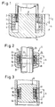
- the electric motor 1 shown in FIG. 1 which is constructed according to the moving coil principle, comprises a permanent magnet 2 which has the shape of a hollow, straight circular cylinder which is open at both ends and which is magnetized such that, for example, its magnetic south pole on its inner cylinder surface 3 and the magnetic north pole lie on its outer cylinder surface 4.
- An electrical coil 6 is arranged in the interior of the permanent magnet 2, which also has the shape of a hollow, straight circular cylinder and whose outer diameter is somewhat smaller than the inner diameter of the permanent magnet 2.
- the axial length L S of the coil 6 is approximately half the axial length of the permanent magnet 2, so that the coil 6, when it is arranged concentrically with the permanent magnet in the interior thereof, moves back and forth in this interior space by a stroke h can, which is approximately equal to the axial length L S of the coil 6 and half the axial length of the permanent magnet 2.
- the electric motor 1 comprises a magnetic yoke made of ferromagnetic material, which has the following components: a jacket 7 in the form of a hollow, straight circular cylinder which has the same axial length as the permanent magnet 2 and surrounds it from the outside in such a way that the inner cylinder surface of the jacket 7 abuts the outer cylinder surface 4 of the permanent magnet 2, a yoke arrangement 8, which essentially has the shape of a circular disk and which forms the lower end wall of the jacket 7 in FIG.
- a core 9 which has the shape of a straight circular cylinder owns and extends from the inner surface of the yoke assembly 8 concentrically over the entire length of the permanent magnet 2 to its upper end in FIG. 1.
- the entire yoke device and thus both the jacket 7 and the core 9 are immovably connected to the permanent magnet 2.
- the relatively movable part is formed by the coil 6, which can move up and down in a cavity which is present between the cylindrical outer surface of the core 9 and the cylinder inner surface 3 of the permanent magnet 2 and has the shape of a straight circular cylinder ring. In order to make this movement possible, corresponding air gaps are left between the core 9 and the inner surface of the coil 6 or the inner cylindrical surface 3 of the permanent magnet 2 and the outer surface of the coil 6.
- the magnetic flux lines running radially inward from the inner surface 3 of the permanent magnet 2 are essentially deflected in the core 9 in such a way that they extend in the longitudinal direction through the core 9 to the yoke arrangement 8, which leads them outward in the radial direction, where they extend from the jacket 7 be returned in the longitudinal direction so far that they can enter the permanent magnet 2 again via the outer surface 4 and close there.
- the diameter of the core 9 must be such that it in the area in which it opens into the yoke arrangement 8 of the total magnetic flux penetrating it there, which is composed of the flux of the permanent magnet 2 and that of the coil 6, is not driven to saturation.
- the axial width of the yoke arrangement 8 can be significantly smaller; it is a quarter of the core diameter. Since the jacket 7 should also not be driven to saturation, its cross-sectional area must not be smaller than that of the core 9. However, this can be achieved with a much smaller material thickness, since the jacket 7 has a greater radial distance from the axis of symmetry.
- the coil 6 is shown in Fig. 1 in the upper end position of its stroke h. If a correspondingly polarized current is applied to it in this position, it moves downward in FIG. 1 until it stops on the yoke device 8, the magnetic flux emanating from the permanent magnet 2 and passing through the coil 6 increasing continuously. If the current flowing through the coil 6 is reversed in the lower end position, it moves up again into the end position shown in FIG. 1, the magnetic flux passing through it continuously decreasing.
- a permanent magnet 12 is again provided in the form of a hollow, straight circular cylinder open at both ends, which is magnetized in the same way , like the permanent magnet 2 in FIG. 1, but which has only about the length of the required stroke h, ie practically only half the length of the permanent magnet 2.
- a coil 14 which also has the shape of a straight hollow circular cylinder and is approximately the same axial Has length as the permanent magnet 12, which rests with its cylinder outer surface 15 on the cylinder inner surface 16 and is fixedly connected thereto and in particular in the longitudinal direction of the arrangement immovably.
- a core 20 made of ferromagnetic material extends through the interior 18, which is enclosed by the coil 14 and is open at both ends, and which is mounted with the aid of two guide disks 21 made of non-ferromagnetic material arranged at the axial ends of the coil 14 such that it is located in can move back and forth in its longitudinal direction.
- each of the two guide disks 21 has a central opening, the shape of which is adapted to the cross-sectional shape of the core 20 and the clear width is dimensioned such that the core is guided in a sliding manner through the two disks 21.
- the core 20 has an “air gap” 22, that is to say a cross-sectional area that is at least largely fulfilled by a material (which also includes a vacuum) that has no ferromagnetic properties.
- This "air gap” 22 thus represents a region with high magnetic resistance, which leads to the fact that the magnetic flux lines which extend radially inward from the permanent magnet 12 and penetrate the body of the coil 14, which in the position of the "air gap” shown in FIG "22 are divided by the latter in such a way that the magnetic flux lines extending above this gap are bent upwards and continued through the ferromagnetic core 20 to the upper front end of the arrangement, while the magnetic flux lines extending below the gap 22 are deflected downwards and to the lower front end be performed.
- the gap 22 moves between two end positions indicated by dashed lines 23,23 ', each of which is defined in that the horizontal gap center line in Fig. 2 with the upper or lower end edge of the coil 14 coincides. It can be seen that in a motor constructed in this way, both the coil 14 and the magnet 12 of approximately the same length need only have the length of the desired stroke h. This results in a minimization of the size in the axial direction.
- the return of the magnetic flux emanating radially inwards from the permanent magnet 12 and deflected in the longitudinal direction in the core 20 also takes place here with the aid of a jacket 24 enclosing the magnet 12 from the outside and a yoke arrangement magnetically connecting the core 20 with the jacket 24 in the radial direction, which here consists of two yokes 25, 26, which essentially have the shape of circular disks tapering radially outward in cross section, each with a central through opening, one of which is arranged at the upper and the other at the lower end of the motor 11.
- the two yokes 25, 26 are firmly connected to the jacket 24 and, like it, consist of a ferromagnetic material.
- the diameters of the central openings allowing the core 20 to pass through the yokes 25, 26 are dimensioned such that the air gap formed between the core 20 and the yokes 25, 26 is small in comparison to the gap 22, but large in comparison with the opposite ones the guide disks 21 existing air gaps. In this way it is achieved that due to eccentricities of the guide between the yokes 25, 26 and the core 20 friction forces occurring are kept very small.
- the width of the air gap that is present between the core 20 and the magnet 12 surrounding it is larger than the width of the air gaps present to the guide disks 21 and in particular larger than the width of the air gap between the core 20 and the yokes 25 and 26. The smallest gap is present between the guide disks 21 and the core 20.
- the guide disks 21 not only reduce the eccentricity force but also fill the necessary spaces between the yokes 25, 26 and the magnet 12.
- the magnet 12 Since, in the embodiment according to the invention according to FIG. 2, the magnet 12 must only have half the length of the permanent magnet from FIG. 1 in order to achieve the stroke h, the magnetic flux emanating from it is also only half as large with the same magnetic strength.
- the core 20 In the embodiment according to FIG. 2, the core 20 must, when the gap 22 is in one of the two end positions, lead the entire magnetic flux of the magnet 12 in the longitudinal direction to the yoke 25 or 26 opposite the gap 22, and because of the 1 and 2 at the highly stressed parts of the core is approximately the same, the diameter of the core 20 must only be a maximum of 1 / ⁇ 2 times as large as in the embodiment of FIG. 1. It can thus by Arrangement according to the invention achieve the same force not only a shortening but also a noticeable reduction in size perpendicular to the longitudinal direction.
- the magnet 32 and the coil 34 have the shape of hollow, straight circular cylinders of the same axial length.
- the coil 34 here has an inner diameter which is equal to the outer diameter of the permanent magnet 32, so that in the assembled state State the coil 34 encloses the permanent magnet 32.
- This sheath like the core 40, which is connected to the two yokes 45, 46 and to the coil-magnet arrangement in the longitudinal direction, is made of ferromagnetic material.
- the longitudinally displaceable jacket 44 here has an "air gap" 42 running transversely to the direction of movement, which, as described above for the gap 22, is at least predominantly filled with some non-ferromagnetic material.
- the jacket 44 slides with its inner cylindrical surface on the outer surfaces of the guide disks 41 and is separated from the yokes 45, 46 and the coil 34 in the same way by air gaps as was described above for the core 20.
- the jacket 44 can move back and forth between two end positions, which are defined in that the horizontal center line of the gap 42 in FIG. 3 is aligned with the upper and lower ends of the coil-magnet arrangement.
- the operation of this embodiment is the same as that of the embodiment of Fig. 2.
- the magnetic flux is the same as that described above.
- the embodiment shown in FIG. 3 has the advantage over the example from FIG. 2 that the friction which occurs in the case of eccentric mounting due to asymmetrically acting magnetic forces between the yokes and the movable body is correspondingly smaller because of the smaller magnetic field strength in the larger radial distance .
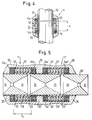
- the outer diameter is further reduced in that the coil 14 is not arranged concentrically to the magnet 12 but is divided into two parts 14a, 14b which can be operated electrically in series or in parallel.
- the non-ferromagnetic cavities required at the ends of the magnet 12 between the magnet and the yokes 25, 26 of the magnetic yoke device are used to accommodate the two partial coils 14a, 14b.
- the result of this is that the field strength can be increased and thus the current of the coil can be reduced.
- the diameter of the core 20 is further reduced because, due to the division of the coil 14 compared to the previous exemplary embodiments, half of the coil cross flow is eliminated.
- the edges of the air gap are preferably rounded off.
- an embodiment can be implemented in which, according to FIG. 3, a jacket having an air gap is mounted such that it can be displaced relative to the rest of the arrangement.
- the magnets 12, 12 'and the coils 14a, 14b and 14a', 14b ' are immovably connected to each other and arranged so that their longitudinal axes are aligned.
- a common core 20 ' can extend through the approximately circular-cylindrical interior of both linear motors 11, 11', which has two gaps 22, 22 'running transversely to its longitudinal direction.
- the axial distance between these two gaps 22, 22 ' is equal to the axial distance between the two electric motors 11, 11', which is defined, for example, by the axial distance between the right-hand end faces in FIG. 5 of the two permanent magnets 12, 12 '.
- the core 20 ' has six frusto-conical recesses 31 which extend coaxially to its longitudinal axis from its end faces or from the two radially extending columns 22, 22' so that its tapered ends point towards one another.
- the recesses 31 serve to save weight and material and are dimensioned so that the remaining ferromagnetic material of the core 20 'is sufficiently thick everywhere from the maximum magnetic flux, which it can enforce in any position of the core 20', in the saturation to be driven.
- the magnetic flux that passes through the middle, two electric motors 11, 11 'common yoke 25' remains approximately the same for all positions of the two columns 22, 22 'when passing through the stroke h and about the size of the maximum magnetic flux is reached by one of the two outer yokes 25, 26.
- the arrangement shown in Fig. 5 comprises two electric motors 11, 11 'of the type shown in Fig. 4, its axial length is considerably less than twice the axial length of a single electric motor 11, because the number of turns of the coils in the Hardly changed compared to an equally powerful single engine.
- this double arrangement is to double the force acting between the stator and the movable motor part under otherwise constant conditions.
- Such doubling of force can also be achieved by using a correspondingly stronger permanent magnet 12 in a single motor 11 according to FIG. 4. Because of the increased magnetic flux, however, this would require a larger core diameter, axially enlarged yokes and a thicker jacket. For the thicker magnet, the outer diameter of the arrangement then increases disproportionately when one wants to use inexpensive magnets.
- It can also be arranged in the manner shown here more than two linear electric motors 11, 11 'one behind the other, which then applies to each yoke lying between two adjacent motors, what was said above for the yoke 25'.
- the jacket 24 'in Fig. 5 each in the middle 27, 27' of the axial length of the two permanent magnets 12, 12 'has a slightly smaller wall thickness than towards the end regions 28.
- This material and weight saving which is also possible in all of the previously described exemplary embodiments can be carried out because a lower magnetic flux must be conducted in these central regions than in the end zones 28.
- air gaps running transversely to the direction of movement can be provided both in the core and in the jacket in the same cross-sectional plane and these two parts can be mechanically connected to one another for a common relative movement to the coil-magnet arrangement.
- the advantage of such an arrangement is that the main coil flow is also halved, whereby the core diameter can be further reduced.
- the main coil flux is understood to mean the magnetic flux which is driven by the entire coil over the entire core, the yokes and the entire jacket.
- the transverse coil flux is a magnetic flux which is driven by the coil or parts of it via part of the core, via a yoke, via part of the jacket and at least part of the magnet.
- coil-magnet arrangements which can be controlled independently of one another in such a way that their longitudinal axes are aligned with one another and / or provide a plurality of slots in the core or in the jacket, in order in this way to accommodate long cores or jackets over long distances move.
- coil-magnet arrangements for example with curved longitudinal axes, can also be arranged on a circular path and used to accelerate an annular core, as a result of which a rotary motor is obtained.
- each of these motors can also be used as generators, ie convert mechanical work into electrical energy.
- the coil arrangement can also comprise a plurality of coils, two of which, for example, are then positioned at the front ends of the magnet arrangement, while a third encloses or is enclosed by the magnet.
- the permanent magnets 12, 32 shown in FIGS. 2 and 3 can also be replaced by electromagnets.
- linear motors according to the invention can either be operated in such a way that they are permanently supplied with a direct current which is polarized in accordance with the desired direction of movement. As an alternative to this, it is also possible to supply them with the electrical energy required to cover a certain distance in separate, poled individual pulses.
Claims (17)
- Moteur électrique linéaire comprenant :- un arrangement de bobines, qui comprend au moins une bobine (14 ; 34 ; 14a, 14b ; 14a, 14b, 14a′, 14b′), qui entoure un espace interne traversant et à travers lequel circule un courant électrique pour générer un déplacement linéaire entre un stator et une partie réactive du moteur,- un arrangement d'aimants qui est relié fixement avec l'arrangement de bobines dans au moins la direction du déplacement linéaire à engendrer et comprend au moins un aimant (12 ; 32 ; 12, 12′), qui est réalisé sous la forme d'un corps allongé dans la direction du déplacement, dont la direction d'aimantation s'étend environ à la perpendiculaire de son axe longitudinal, qui entoure un espace intérieur traversant et qui est disposé par rapport à l'espace intérieur de ladite au moins une bobine (14 ; 34 ; 14a, 14b ; 14a, 14b, 14a′, 14b′) de manière coaxiale telle que son champ magnétique traverse l'arrangement de bobines,- ainsi qu'un arrangement de guidage de flux, qui comprend les éléments suivants :dans lequel au moins un des deux éléments formés par le noyau (20 ; 40 ; 20′) et l'enveloppe (24 ; 44; 24′) de l'arrangement de guidage de flux est monté mobile dans la direction de déplacement linéaire par rapport aux arrangements de bobine et d'aimant et est séparé des culasses (25, 26; 25, 25′, 26′; 45, 46) par des fentes et présente au moins une fente (22 ; 42 ; 22, 22′) s'étendant transversalement à la direction du déplacement linéaire, qui est remplie avec un matériau présentant une faible perméabilité magnétique, de sorte qu'il forme une résistance magnétique supérieure à celle des fentes adjacentes aux culasses (25, 26 ; 25, 25′, 26′; 45, 46) et celui-ci est disposé de telle sorte que le flux magnétique dans l'arrangement de bobine varie en raison de son déplacement par rapport aux arrangements de bobine et d'aimant ;. un noyau (20, 40 ; 20′) qui est constitué au moins partiellement d'un matériau ferromagnétique et qui s'étend à travers l'espace intérieur de ladite au moins une bobine (14 ; 34 ; 14a, 14b ; 14a, 14b, 14a′, 14b′) et à travers l'espace intérieur dudit au moins un aimant (12 ; 32 ; 12, 12′),. une enveloppe (24 ; 44 ; 24′) sous la forme d'un corps allongé dans la direction de déplacement, qui est constituée au moins partiellement d'un matériau ferromagnétique et qui entoure de l'extérieur les arrangements de bobine et d'aimant, et. au moins deux culasses (25, 26 ; 25, 25′, 26′ ; 45, 46) en matériau ferromagnétique, qui réalisent transversalement à la direction de déplacement une liaison de flux magnétique entre le noyau (20; 40; 20′) et l'enveloppe (24 ; 44 ; 24′),
caractérisé en ce que au moins un élément mobile de l'arrangement de guidage de flux est guidé par rapport aux arrangements de bobine et d'aimant à l'aide d'éléments de guidage (21; 41; 30, 30′) réalisés en un matériau non magnétique, qui sont séparés de l'élément mobile par des entrefers, qui sont petits en comparaison auxdites fentes entre l'élément mobile et les culasses (25, 26 ; 25, 25′, 26′; 45, 46). - Moteur linéaire selon la revendication 1, caractérisé en ce que, aux positions de transition entre l'élément mobile de l'arrangement de guidage de flux et les culasses, est introduit un liquide ferromagnétique, avantageusement à base d'huile.
- Moteur linéaire selon la revendication 1 ou la revendication 2, caractérisé en ce que l'arrangement de bobine comprend une seule bobine (14), qui est réalisée sous la forme d'un corps allongé dans la direction de déplacement, et en ce que l'arrangement d'aimant comprend un seul aimant (12), qui entoure la bobine (14) de l'extérieur.
- Moteur linéaire selon la revendication 1 ou la revendication 2, caractérisé en ce que l'arrangement de bobine comprend une seule bobine (34), qui est réalisée sous la forme d'un corps allongé dans la direction de déplacement, et en ce que l'arrangement d'aimant comprend un seul aimant (32), qui est entouré de l'extérieur par la bobine (34).
- Moteur linéaire selon l'une des revendications 3 ou 4, caractérisé en ce que la bobine (14 ; 34) ainsi que l'aimant (12 ; 32) sont réalisés sous la forme d'un cylindre creux droit avec une section transversale intérieure et extérieure circulaire.
- Moteur linéaire selon la revendication 1 ou la revendication 2, caractérisé en ce que l'arrangement d'aimant est constitué d'un seul aimant (12 ; 12, 12′), en ce que l'arrangement de bobine comprend deux bobines (14a, 14b ; 14a, 14b, 14a′, 14b′) actionnables dans le même sens, qui se raccordent à l'aimant (12 ; 12, 12′) à ses deux extrémités frontales, de telle sorte que les espaces intérieurs des bobines sont au moins environ alignés avec l'espace intérieur de l'aimant.
- Moteur linéaire selon la revendication 6, caractérisé en ce que chacune des deux bobines (14a, 14b ; 14a, 14b, 14a′, 14b′) et l'aimant (12 ; 12, 12′) sont réalisés sous la forme de cylindres creux droits avec des sections transversales intérieures et extérieures circulaires.
- Moteur linéaire selon l'une des revendications 1 à 7, caractérisé en ce que le noyau (20, 20′) est monté mobile dans la direction du déplacement linéaire par rapport à l'arrangement de bobine et d'aimant et en ce que les culasses (25, 26 ; 25, 25′, 26′) sont solidement reliées à l'enveloppe (24, 24′), qui est reliée fixement à l'arrangement de bobine et d'aimant au moins en direction du déplacement linéaire.
- Moteur linéaire selon l'une des revendications 1 à 7, caractérisé en ce que l'enveloppe (44) est montée mobile par rapport à l'arrangement de bobine et d'aimant et en ce que les culasses (45, 46) sont solidement reliées au noyau (40), qui est relié fixement à l'arrangement de bobine et d'aimant au moins en direction du déplacement linéaire.
- Moteur linéaire selon l'une des revendications 1 à 7, caractérisé en ce que le noyau et l'enveloppe sont montés mobiles par rapport à l'arrangement de bobine et d'aimant au moins en direction du déplacement linéaire, et en ce que les culasses sont reliées fixement avec l'arrangement de bobine et d'aimant au moins en direction du déplacement linéaire.
- Moteur linéaire selon l'une quelconque des revendications précédentes, caractérisé en ce que l'arrangement d'aimant est formé d'aimants permanents.
- Moteur linéaire selon l'une quelconque des revendications précédentes, caractérisé en ce que ladite au moins une fente (22 ; 42 ; 22′) dans l'élément mobile par rapport à l'arrangement de bobine et d'aimant d'arrangement de guidage de flux est remplie avec un matériau solide présentant une faible perméabilité magnétique, qui forme avec l'élément mobile un corps global avec un profil extérieur continu.
- Moteur linéaire selon l'une quelconque des revendications précédentes, caractérisé en ce que l'épaisseur de matériau et la forme du noyau, des culasses et de l'enveloppe dans les différentes zones de section transversale sont adaptées au flux magnétique maximal traversant la zone de section transversale respective de telle sorte qu'avec une utilisation de matériau la plus faible possible, une saturation est évitée.
- Moteur linéaire selon la revendication 13, caractérisé en ce que le noyau (20′) présente des évidements tronconiques (31), qui s'étendent vers l'intérieur de celui-ci de manière coaxiale à son axe longitudinal à partir de ses sufaces frontales et de la fente s'étendant radialement (22, 22′) de telle sorte que ses extrémités réduites se font face.
- Arrangement de moteur linéaire, comprenant au moins deux moteurs linéaires (11, 11′) selon l'une quelconque des revendications précédentes, caractérisé en ce que les arrangements de bobine et d'aimant desdits au moins deux moteurs linéaires (11, 11′) sont tous reliés ensemble de manière fixe au moins en direction du déplacement linéaire, en ce qu'au moins un élément mobile commun de l'arrangement de guidage de flux est prévu pour lesdits au moins deux moteurs linéaires, ledit élément mobile présentant une fente (22, 22′) pour chacun des moteurs linéaires (11, 11′), et en ce que l'arrangement de bobine desdits au moins deux moteurs linéaires (11, 11′) est commandé de telle sorte les forces générées entre l'arrangement de bobine et d'aimant de chaque moteur linéaire (11, 11′) et l'élément mobile commun de l'arrangement de guidage de flux agissent pour produire un déplacement linéaire dans le même sens.
- Arrangement de moteur linéaire selon la revendication 15, caractérisé en ce que lesdits au moins deux moteurs linéaires (11, 11′) présentent une enveloppe commune (24′) et en ce qu'il est associé deux moteurs linéaires (11,11′) à au moins une (25′) des culasses (25, 25′, 26).
- Utilisation d'un moteur linéaire selon l'une des revendications précédentes en tant que générateur électrique.
Priority Applications (1)
| Application Number | Priority Date | Filing Date | Title |
|---|---|---|---|
| EP93113018A EP0574960B1 (fr) | 1990-02-16 | 1991-02-13 | Moteur électrique rotatif |
Applications Claiming Priority (2)
| Application Number | Priority Date | Filing Date | Title |
|---|---|---|---|
| DE4005045 | 1990-02-16 | ||
| DE4005045 | 1990-02-16 |
Related Child Applications (2)
| Application Number | Title | Priority Date | Filing Date |
|---|---|---|---|
| EP93113018A Division EP0574960B1 (fr) | 1990-02-16 | 1991-02-13 | Moteur électrique rotatif |
| EP93113018.1 Division-Into | 1993-08-13 |
Publications (3)
| Publication Number | Publication Date |
|---|---|
| EP0450288A2 EP0450288A2 (fr) | 1991-10-09 |
| EP0450288A3 EP0450288A3 (en) | 1991-11-06 |
| EP0450288B1 true EP0450288B1 (fr) | 1995-06-28 |
Family
ID=6400408
Family Applications (2)
| Application Number | Title | Priority Date | Filing Date |
|---|---|---|---|
| EP93113018A Expired - Lifetime EP0574960B1 (fr) | 1990-02-16 | 1991-02-13 | Moteur électrique rotatif |
| EP91102029A Expired - Lifetime EP0450288B1 (fr) | 1990-02-16 | 1991-02-13 | Moteur électrique linéaire |
Family Applications Before (1)
| Application Number | Title | Priority Date | Filing Date |
|---|---|---|---|
| EP93113018A Expired - Lifetime EP0574960B1 (fr) | 1990-02-16 | 1991-02-13 | Moteur électrique rotatif |
Country Status (4)
| Country | Link |
|---|---|
| US (1) | US5220223A (fr) |
| EP (2) | EP0574960B1 (fr) |
| JP (1) | JPH04217853A (fr) |
| DE (2) | DE59105817D1 (fr) |
Families Citing this family (20)
| Publication number | Priority date | Publication date | Assignee | Title |
|---|---|---|---|---|
| US5907202A (en) * | 1995-08-28 | 1999-05-25 | Mikuni Corporation | Thermo-sensitive actuator and idle speed controller employing the same |
| US5742106A (en) * | 1995-08-28 | 1998-04-21 | Mikuni Corporation | Thermo-sensitive actuator and idle speed controller employing the same |
| FR2746558B1 (fr) * | 1996-03-22 | 1998-04-24 | Gec Alsthom Moteurs Sa | Rotor magnetoelectrique a griffes, procede de fabrication d'un tel rotor |
| US5973422A (en) * | 1998-07-24 | 1999-10-26 | The Guitammer Company | Low frequency vibrator |
| US6242823B1 (en) | 1999-02-05 | 2001-06-05 | Wayne Griswold | Linear electric machine |
| US6914351B2 (en) * | 2003-07-02 | 2005-07-05 | Tiax Llc | Linear electrical machine for electric power generation or motive drive |
| US7679647B2 (en) * | 2004-07-21 | 2010-03-16 | Hewlett-Packard Development Company, L.P. | Flexible suspension for image stabilization |
| US7710460B2 (en) * | 2004-07-21 | 2010-05-04 | Hewlett-Packard Development Company, L.P. | Method of compensating for an effect of temperature on a control system |
| US7081696B2 (en) | 2004-08-12 | 2006-07-25 | Exro Technologies Inc. | Polyphasic multi-coil generator |
| WO2007061920A2 (fr) * | 2005-11-17 | 2007-05-31 | Tiax Llc | Machine electrique lineaire pour generation d'energie electrique ou entrainement moteur |
| CA2654462A1 (fr) | 2006-06-08 | 2007-12-13 | Exro Technologies Inc. | Generateur multi-bobines polyphasique |
| US7834622B2 (en) * | 2007-10-18 | 2010-11-16 | Baker Hughes Incorporated | Configurable magnet assembly for using in NMR well logging instrument |
| US9325232B1 (en) | 2010-07-22 | 2016-04-26 | Linear Labs, Inc. | Method and apparatus for power generation |
| BR112013009476B1 (pt) | 2010-10-22 | 2021-06-22 | Linear Labs, Inc. | Parelho de motor elétrico e método para produzir um ciclo de curso de mecanismo motor |
| WO2014036567A1 (fr) | 2012-09-03 | 2014-03-06 | Linear Labs, Inc. | Transducteur amélioré et procédé de fonctionnement |
| US9219962B2 (en) | 2012-09-03 | 2015-12-22 | Linear Labs, Inc. | Transducer and method of operation |
| WO2014165790A1 (fr) | 2013-04-04 | 2014-10-09 | L-3 Communications Cincinnati Electronics Corporation | Transducteurs électromagnétiques à centrage automatique |
| CA3061619C (fr) | 2017-05-23 | 2022-09-06 | Dpm Technologies Inc. | Appareil, procede et systeme temoin de configuration d'une bobine variable |
| CA3137550A1 (fr) | 2019-04-23 | 2020-10-29 | Dpm Technologies Inc. | Machine electrique rotative tolerante aux defaillances |
| WO2022232904A1 (fr) | 2021-05-04 | 2022-11-10 | Exro Technologies Inc. | Systèmes et procédés de commande de batterie |
Family Cites Families (10)
| Publication number | Priority date | Publication date | Assignee | Title |
|---|---|---|---|---|
| FR513515A (fr) * | 1919-03-03 | 1921-02-17 | Olivetti & Co Spa | Machine magnéto-électrique à aimants et induit fixes |
| CH251509A (de) * | 1946-01-14 | 1947-10-31 | Winet Hans | Synchronmotor. |
| DE852263C (de) * | 1950-05-25 | 1952-10-13 | Aeg | Elektrische Synchronmaschine mit Wechselpolen |
| US3190608A (en) * | 1962-02-07 | 1965-06-22 | Kromschroeder Ag G | Electromagnetically controlled valve |
| US3321652A (en) * | 1963-12-23 | 1967-05-23 | North American Aviation Inc | Dynamo-electric machine |
| JPS5027579A (fr) * | 1973-07-09 | 1975-03-20 | ||
| US4243899A (en) * | 1979-03-08 | 1981-01-06 | The Singer Company | Linear motor with ring magnet and non-magnetizable end caps |
| US4697113A (en) * | 1985-08-01 | 1987-09-29 | Helix Technology Corporation | Magnetically balanced and centered electromagnetic machine and cryogenic refrigerator employing same |
| GB2205003B (en) * | 1987-05-18 | 1991-05-29 | Sony Corp | Magnetic circuits of linear motors |
| JPH06231362A (ja) * | 1993-01-29 | 1994-08-19 | Hitachi Ltd | キャッシュレジスタを利用した現金集計システム |
-
1991
- 1991-02-13 DE DE59105817T patent/DE59105817D1/de not_active Expired - Fee Related
- 1991-02-13 DE DE59106499T patent/DE59106499D1/de not_active Expired - Fee Related
- 1991-02-13 EP EP93113018A patent/EP0574960B1/fr not_active Expired - Lifetime
- 1991-02-13 EP EP91102029A patent/EP0450288B1/fr not_active Expired - Lifetime
- 1991-02-15 US US07/655,607 patent/US5220223A/en not_active Expired - Fee Related
- 1991-02-16 JP JP3044152A patent/JPH04217853A/ja active Pending
Non-Patent Citations (1)
| Title |
|---|
| Patent Abstracts of Japan, Vol 11, N0 209 (E521)(2656) July 7 1987 & JP-A-6231362 (Hitachi) 10.02.87 * |
Also Published As
| Publication number | Publication date |
|---|---|
| EP0450288A3 (en) | 1991-11-06 |
| US5220223A (en) | 1993-06-15 |
| EP0450288A2 (fr) | 1991-10-09 |
| EP0574960A2 (fr) | 1993-12-22 |
| JPH04217853A (ja) | 1992-08-07 |
| DE59106499D1 (de) | 1995-10-19 |
| EP0574960A3 (fr) | 1994-01-26 |
| EP0574960B1 (fr) | 1995-09-13 |
| DE59105817D1 (de) | 1995-08-03 |
Similar Documents
| Publication | Publication Date | Title |
|---|---|---|
| EP0450288B1 (fr) | Moteur électrique linéaire | |
| DE3009735C2 (de) | Elektrischer Linearmotor | |
| CH628475A5 (de) | Hochleistungsschrittmotor. | |
| EP0329950A2 (fr) | Amortisseur hydraulique | |
| DE69830916T2 (de) | Elektromagnetische vorrichtung zur erzeugung einer linearen bewegung | |
| EP1445432B1 (fr) | Commande de soupape d'un moteur à combustion interne controllé par les soupapes | |
| DE102013108164B4 (de) | Ventil mit einem Linearantrieb für den Ventilkolben | |
| DE4421594A1 (de) | Vorrichtung zur Veränderung der magnetischen Luftspaltinduktion in elektromechanischen Energiewandlern, bei denen der magnetische Widerstand des magnetischen Schließungskreises in der Maschine variabel ist | |
| DE19606836A1 (de) | Vorrichtung und Verfahren zum Betätigen eines für die Steuerung der Leerlaufdrehzahl verwendeten Ventils | |
| DE3020852A1 (de) | Linearmotor | |
| EP0937328B1 (fr) | Mecanisme de reglage a moteur electrique | |
| DE3006354C2 (de) | Zylindrischer linearer Asynchronmotor | |
| EP1869756B1 (fr) | Actionneur lineaire | |
| EP0555523A1 (fr) | Support caoutchouc | |
| DE102014213276A1 (de) | Linearantrieb mit hoher Kraftdichte | |
| DE19900788B4 (de) | Antriebsvorrichtung | |
| EP0569669B1 (fr) | Moteur linéaire électromagnétique à double effet | |
| DE3934287A1 (de) | Magnetventil | |
| DE602005002195T2 (de) | Linear Betätiger mit direktem Antrieb | |
| DE10044789C2 (de) | Antiebsvorrichtung eines Gaswechselventils für einen ventilgesteuerten Verbrennungsmotor | |
| DE102005051235A1 (de) | Elektrodynamischer Linearmotor | |
| EP0224815A2 (fr) | Système de clapet réglable pour un amortisseur de vibrations et procédé pour son réglage ou ajustement | |
| DE3032308A1 (de) | Elektromagnetische einrichtung mit sich bewegender linearantriebsspule | |
| DE4215011B4 (de) | Elektromagnetischer Verstellantrieb | |
| DE4107530A1 (de) | Linearmotor i |
Legal Events
| Date | Code | Title | Description |
|---|---|---|---|
| PUAI | Public reference made under article 153(3) epc to a published international application that has entered the european phase |
Free format text: ORIGINAL CODE: 0009012 |
|
| PUAL | Search report despatched |
Free format text: ORIGINAL CODE: 0009013 |
|
| AK | Designated contracting states |
Kind code of ref document: A2 Designated state(s): CH DE ES FR GB IT LI NL |
|
| AK | Designated contracting states |
Kind code of ref document: A3 Designated state(s): CH DE ES FR GB IT LI NL |
|
| 17P | Request for examination filed |
Effective date: 19920430 |
|
| 17Q | First examination report despatched |
Effective date: 19921012 |
|
| RTI1 | Title (correction) | ||
| GRAA | (expected) grant |
Free format text: ORIGINAL CODE: 0009210 |
|
| AK | Designated contracting states |
Kind code of ref document: B1 Designated state(s): CH DE ES FR GB IT LI NL |
|
| PG25 | Lapsed in a contracting state [announced via postgrant information from national office to epo] |
Ref country code: NL Free format text: LAPSE BECAUSE OF FAILURE TO SUBMIT A TRANSLATION OF THE DESCRIPTION OR TO PAY THE FEE WITHIN THE PRESCRIBED TIME-LIMIT Effective date: 19950628 Ref country code: ES Free format text: THE PATENT HAS BEEN ANNULLED BY A DECISION OF A NATIONAL AUTHORITY Effective date: 19950628 |
|
| XX | Miscellaneous (additional remarks) |
Free format text: TEILANMELDUNG 93113018.1 EINGEREICHT AM 13/02/91. |
|
| REF | Corresponds to: |
Ref document number: 59105817 Country of ref document: DE Date of ref document: 19950803 |
|
| ITF | It: translation for a ep patent filed |
Owner name: ING. DR. LAZZARO MARTINI S.R.L. |
|
| GBT | Gb: translation of ep patent filed (gb section 77(6)(a)/1977) |
Effective date: 19950921 |
|
| ET | Fr: translation filed | ||
| NLV1 | Nl: lapsed or annulled due to failure to fulfill the requirements of art. 29p and 29m of the patents act | ||
| PLBE | No opposition filed within time limit |
Free format text: ORIGINAL CODE: 0009261 |
|
| STAA | Information on the status of an ep patent application or granted ep patent |
Free format text: STATUS: NO OPPOSITION FILED WITHIN TIME LIMIT |
|
| 26N | No opposition filed | ||
| K1C3 | Correction of patent application (complete document) published |
Effective date: 19911009 |
|
| REG | Reference to a national code |
Ref country code: GB Ref legal event code: IF02 |
|
| PGFP | Annual fee paid to national office [announced via postgrant information from national office to epo] |
Ref country code: GB Payment date: 20020204 Year of fee payment: 12 |
|
| PGFP | Annual fee paid to national office [announced via postgrant information from national office to epo] |
Ref country code: CH Payment date: 20020220 Year of fee payment: 12 |
|
| PGFP | Annual fee paid to national office [announced via postgrant information from national office to epo] |
Ref country code: FR Payment date: 20020221 Year of fee payment: 12 |
|
| PGFP | Annual fee paid to national office [announced via postgrant information from national office to epo] |
Ref country code: DE Payment date: 20020430 Year of fee payment: 12 |
|
| PG25 | Lapsed in a contracting state [announced via postgrant information from national office to epo] |
Ref country code: GB Free format text: LAPSE BECAUSE OF NON-PAYMENT OF DUE FEES Effective date: 20030213 |
|
| PG25 | Lapsed in a contracting state [announced via postgrant information from national office to epo] |
Ref country code: LI Free format text: LAPSE BECAUSE OF NON-PAYMENT OF DUE FEES Effective date: 20030228 Ref country code: CH Free format text: LAPSE BECAUSE OF NON-PAYMENT OF DUE FEES Effective date: 20030228 |
|
| PG25 | Lapsed in a contracting state [announced via postgrant information from national office to epo] |
Ref country code: DE Free format text: LAPSE BECAUSE OF NON-PAYMENT OF DUE FEES Effective date: 20030902 |
|
| GBPC | Gb: european patent ceased through non-payment of renewal fee | ||
| REG | Reference to a national code |
Ref country code: CH Ref legal event code: PL |
|
| PG25 | Lapsed in a contracting state [announced via postgrant information from national office to epo] |
Ref country code: FR Free format text: LAPSE BECAUSE OF NON-PAYMENT OF DUE FEES Effective date: 20031031 |
|
| REG | Reference to a national code |
Ref country code: FR Ref legal event code: ST |
|
| PG25 | Lapsed in a contracting state [announced via postgrant information from national office to epo] |
Ref country code: IT Free format text: LAPSE BECAUSE OF NON-PAYMENT OF DUE FEES;WARNING: LAPSES OF ITALIAN PATENTS WITH EFFECTIVE DATE BEFORE 2007 MAY HAVE OCCURRED AT ANY TIME BEFORE 2007. THE CORRECT EFFECTIVE DATE MAY BE DIFFERENT FROM THE ONE RECORDED. Effective date: 20050213 |