EP1445357A2 - Garnabzugsdüse für Offenend-Rotorspinnvorrichtung - Google Patents
Garnabzugsdüse für Offenend-Rotorspinnvorrichtung Download PDFInfo
- Publication number
- EP1445357A2 EP1445357A2 EP03026449A EP03026449A EP1445357A2 EP 1445357 A2 EP1445357 A2 EP 1445357A2 EP 03026449 A EP03026449 A EP 03026449A EP 03026449 A EP03026449 A EP 03026449A EP 1445357 A2 EP1445357 A2 EP 1445357A2
- Authority
- EP
- European Patent Office
- Prior art keywords
- yarn
- contact surface
- nozzle
- take
- open
- Prior art date
- Legal status (The legal status is an assumption and is not a legal conclusion. Google has not performed a legal analysis and makes no representation as to the accuracy of the status listed.)
- Withdrawn
Links
Images

Classifications
-
- D—TEXTILES; PAPER
- D01—NATURAL OR MAN-MADE THREADS OR FIBRES; SPINNING
- D01H—SPINNING OR TWISTING
- D01H4/00—Open-end spinning machines or arrangements for imparting twist to independently moving fibres separated from slivers; Piecing arrangements therefor; Covering endless core threads with fibres by open-end spinning techniques
- D01H4/40—Removing running yarn from the yarn forming region, e.g. using tubes
Definitions
- the invention relates to a yarn take-off nozzle for open-end rotor spinning devices, with a pulling and at the same time rotating yarn deflecting arched contact surface, the is interrupted by at least one abrupt depression such that the yarn in Circulation direction briefly loses contact with the contact surface.
- Yarn take-off nozzles guide the spun yarn from the heart of an open-end rotor spinning device, the so-called spinning rotor, to the outside.
- the formation of the yarn take-off nozzle itself has a major impact on both the quality of the spun yarn and the Spinning stability of the open-end rotor spinning device.
- Smooth yarn take-off nozzles lead to one good yarn quality, but have a rather poor spinning stability.
- With innterruptions provided, for example notched yarn take-off nozzles increase the spinning stability, worsen however the yarn quality. Due to the notches, extreme yarn tension peaks between the Spinning rotor and the yarn take-off nozzle generated. However, the yarn tension peaks lead Amazingly, not to yarn breaks, but to a more stable spinning process.
- the abrupt depressions are notches in the Contact surface incorporated, with the contact surface in each case between two depressions the yarn tensions have a constant normal level, as it were, to the individual wells are then left for a while, leaving the surrounding yarn in the area of these depressions without contact with the yarn take-off nozzle.
- the invention is based on the object in terms of yarn quality and spinning stability to find a good compromise based on the good experience of the well-known yarn take-off nozzle builds up, but the circulating yarn does not touch itself over such long distances leaves the contact surface.
- the object is achieved in a yarn draw-off nozzle of the type described in the introduction in that the contact surface in the circumferential direction of the yarn up to the abrupt deepening as a gently rising is formed over a circumferential angle of at least 45 ° extending elevation.
- the circumferential yarn has the opportunity at each recess Abruptly reduce thread tension without unnecessarily stressing the surface of the thread becomes.
- the voltage reduction is always only very short, at least significantly shorter than with described prior art, so that caused by yarn tensions Irregularities are far less disadvantageous.
- the contact surface of the gently rising elevation can be easily be concave. This brings the circulating yarn faster to a desired one Yarn tension level, so that the total contact area with a larger number of Wells can be provided. From a certain number of specializations, this is the case that a plurality of elevations formed as ribs are then provided.
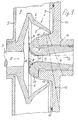
- FIG. 1 An open-end rotor spinning device shown only partially in FIG. 1 contains a spinning rotor 1, which consists of a rotor plate 2 and a shaft 3 pressed therein.
- the shaft 3 is in stored and driven, not shown.
- the rotor plate 2 rotates in operation in one Vacuum chamber 4, which is formed by a rotor housing 5, which is not shown in Way is connected to a vacuum source.
- the rotor plate 2 has a fiber sliding surface 7 which widens conically to form a fiber collecting groove 6.
- the hollow interior of the rotor plate 2 has its largest diameter.
- the spinning rotor 1. can be pulled out through a front opening 8 of the rotor housing 5 to the operating side.
- the opening 8 of the rotor housing 5 is closed together with the open front 9 of the rotor plate 2 by a cover 10 which can be moved away.
- the cover 10 then lies against the rotor housing 5 with the interposition of an annular seal 11.
- the cover 10 contains a fiber feed channel 12 lying outside the plane of the drawing, which begins in a manner which is not shown, because it is known, at an opening roller and whose mouth 13 is directed against the fiber sliding surface 7.
- fibers are shot during operation through the opening roller through the fiber feed channel 12 against the fiber sliding surface 7, from where they slide into the fiber collecting groove 6, form a fiber ring there and in a known manner as yarn 14 shown in broken lines in the axial direction of the Shaft 3 are withdrawn.
- the transport air sucked in via the fiber feed channel 12 can flow out via an overflow gap 15 of the open front side 9 of the spinning rotor 1.
- the spun yarn 14 is first at least approximately from the fiber collecting groove 6 in a normal plane of the spinning rotor 1 lying to the shaft 3 and then over one Yarn take-off channel 16 of a yarn take-off nozzle 17 according to take-off direction A by means of a not Draw-off roller pair shown and a package, also not shown fed.
- the yarn take-off channel 16 is coaxial with the shaft 3 of the spinning rotor 1, so that Yarn 14 is deflected by about 90 ° by means of the yarn take-off nozzle 17, the yarn 14 in the mentioned normal plane corresponding to the direction of rotation B of the rotor plate 2 (compare Figures 2 and 3) revolves like a crank.
- the yarn take-off nozzle 17 is in one by means of an external thread 18 or other holding means corresponding hole in the cover 10 screwed.
- the deflection of the yarn 14 from the normal plane in the yarn take-off channel 16 is used on the yarn take-off nozzle 17
- Existing funnel-shaped arched contact surface 19, which lies on a in the normal plane End face begins.
- the contact surface 19 is in Essentially an arcuate surface, which is directly the smallest cross section 20 of the yarn take-off channel 16 follows.
- the contact surface 19 forms in the axial section shown in FIG about a quarter circle with a radius of curvature that is, for example, three millimeters.
- the yarn draw-off nozzle 17 has a considerable influence on the current one Yarn twist in the fiber collecting groove 6 at the moment the yarn 14 is created.
- depressions 21 are made in the contact surface 19, which are essentially run radially to the yarn take-off channel 16 and increase the spinning stability, ie the risk of Reduce yarn breaks.
Landscapes
- Engineering & Computer Science (AREA)
- Mechanical Engineering (AREA)
- Textile Engineering (AREA)
- Spinning Or Twisting Of Yarns (AREA)
Abstract
Description
Die Abdeckung 10 enthält einen außerhalb der Zeichenebene liegenden Faserzuführkanal 12, der in nicht dargestellter, weil bekannter Weise an einer Auflösewalze beginnt und dessen Mündung 13 gegen die Fasergleitfläche 7 gerichtet ist. Durch die Wirkung der genannten Unterdruckquelle werden bei Betrieb durch die Auflösewalze vereinzelte Fasern durch den Faserzuführkanal 12 gegen die Fasergleitfläche 7 geschossen, von wo sie in die Fasersammelrille 6 gleiten, dort einen Faserring bilden und in bekannter Weise als strichpunktiert dargestelltes Garn 14 in axialer Richtung des Schaftes 3 abgezogen werden. Die über den Faserzuführkanal 12 angesaugte Transportluft kann über einen Überströmspalt 15 der offenen Vorderseite 9 des Spinnrotors 1 abfließen.
Claims (3)
- Garnabzugsdüse für Offenend-Rotorspinnvorrichtungen, mit einer ein abzuziehendes und dabei zugleich umlaufendes Garn umlenkenden gewölbten Kontaktfläche, die durch wenigstens eine abrupte Vertiefung derart unterbrochen ist, dass das Garn in Umlaufrichtung kurzzeitig seinen Kontakt zur Kontaktfläche verliert, dadurch gekennzeichnet, dass die Kontaktfläche (19) in Umlaufrichtung (B) des Garnes (14) bis zur abrupten Vertiefung (21) als sanft ansteigende, sich über einen Umfangswinkel (α) von wenigstens 45° erstreckende Erhebung (22) ausgebildet ist.
- Garnabzugsdüse nach Anspruch 1, dadurch gekennzeichnet, dass die Kontaktfläche (19) der sanft ansteigenden Erhebung (22) leicht konkav ausgebildet ist.
- Garnabzugsdüse nach Anspruch 1 oder 2, dadurch gekennzeichnet, dass eine Mehrzahl von als Rippen ausgebildeten Erhebungen (22) vorgesehen ist.
Applications Claiming Priority (2)
| Application Number | Priority Date | Filing Date | Title |
|---|---|---|---|
| DE10305794 | 2003-02-10 | ||
| DE2003105794 DE10305794B4 (de) | 2003-02-10 | 2003-02-10 | Garnabzugsdüse für Offenend-Rotorspinnvorrichtungen |
Publications (2)
| Publication Number | Publication Date |
|---|---|
| EP1445357A2 true EP1445357A2 (de) | 2004-08-11 |
| EP1445357A3 EP1445357A3 (de) | 2005-04-13 |
Family
ID=32603235
Family Applications (1)
| Application Number | Title | Priority Date | Filing Date |
|---|---|---|---|
| EP03026449A Withdrawn EP1445357A3 (de) | 2003-02-10 | 2003-11-20 | Garnabzugsdüse für Offenend-Rotorspinnvorrichtung |
Country Status (2)
| Country | Link |
|---|---|
| EP (1) | EP1445357A3 (de) |
| DE (1) | DE10305794B4 (de) |
Cited By (1)
| Publication number | Priority date | Publication date | Assignee | Title |
|---|---|---|---|---|
| CN110747544A (zh) * | 2019-11-05 | 2020-02-04 | 安徽翰联色纺股份有限公司 | 一种涡流纺纱线用的固定装置 |
Families Citing this family (1)
| Publication number | Priority date | Publication date | Assignee | Title |
|---|---|---|---|---|
| DE102022114064A1 (de) | 2022-06-03 | 2023-12-14 | Saurer Spinning Solutions Gmbh & Co. Kg | Fadenabzugsdüse sowie Offenend-Spinnvorrichtung mit einer Fadenabzugsdüse |
Family Cites Families (5)
| Publication number | Priority date | Publication date | Assignee | Title |
|---|---|---|---|---|
| DE2140157B2 (de) * | 1971-08-11 | 1973-11-29 | Schubert & Salzer Maschinenfabrik Ag, 8070 Ingolstadt | Fadenabzugsrohr für eine Offen-End-Spinnvorrichtung |
| DE3934166C2 (de) * | 1989-10-12 | 1994-06-09 | Rieter Ingolstadt Spinnerei | Offenend-Spinnvorrichtung |
| DE19906111A1 (de) * | 1999-02-13 | 2000-10-05 | Felix Backmeister | Faden-Abzugsdüse in einer Open-End-Spinnmaschine |
| DE19949533A1 (de) * | 1999-10-14 | 2001-04-19 | Schlafhorst & Co W | Offenend-Rotorspinnvorrichtung |
| DE10001468A1 (de) * | 2000-01-15 | 2001-07-19 | Rieter Ingolstadt Spinnerei | Fadenabzugsdüse für eine Offenend-Spinnmaschine |
-
2003
- 2003-02-10 DE DE2003105794 patent/DE10305794B4/de not_active Expired - Fee Related
- 2003-11-20 EP EP03026449A patent/EP1445357A3/de not_active Withdrawn
Cited By (2)
| Publication number | Priority date | Publication date | Assignee | Title |
|---|---|---|---|---|
| CN110747544A (zh) * | 2019-11-05 | 2020-02-04 | 安徽翰联色纺股份有限公司 | 一种涡流纺纱线用的固定装置 |
| CN110747544B (zh) * | 2019-11-05 | 2021-09-17 | 安徽翰联色纺股份有限公司 | 一种涡流纺纱线用的固定装置 |
Also Published As
| Publication number | Publication date |
|---|---|
| DE10305794B4 (de) | 2012-01-19 |
| EP1445357A3 (de) | 2005-04-13 |
| DE10305794A1 (de) | 2004-08-19 |
Similar Documents
| Publication | Publication Date | Title |
|---|---|---|
| DE19738382B4 (de) | Fadenabzugsdüse | |
| WO2006027216A1 (de) | Luftdüsenspinnvorrichtung | |
| DE2351561A1 (de) | Offen-end-spinnverfahren und vorrichtung zur durchfuehrung des verfahrens | |
| DE2016469A1 (de) | Open-end-Spinnvorrichtung | |
| DE1710022A1 (de) | Kapselspinnmaschine | |
| EP0422615B1 (de) | Offenend-Spinnvorrichtung | |
| AT501520B1 (de) | Garnabzugseinrichtung für offenend-spinnvorrichtungen | |
| CH645413A5 (de) | Offenend-spinnvorrichtung. | |
| EP1375711B1 (de) | Garnabzugsdüse für eine Offenend-Spinnvorrichtung | |
| AT504812A1 (de) | Garnabzugsdüse für eine offenend- rotorspinnvorrichtung | |
| EP0992619B2 (de) | Offenend-spinnrotor | |
| DE10305794B4 (de) | Garnabzugsdüse für Offenend-Rotorspinnvorrichtungen | |
| CH674746A5 (de) | ||
| DE2250831A1 (de) | Offen-end-spinnvorrichtung | |
| AT501433B1 (de) | Garnabzugsdüse für offenend-spinnvorrichtungen | |
| DE3942454A1 (de) | Verfahren und einrichtung zum herstellen eines spinnfasergarns | |
| AT500772B1 (de) | Garnabzugsdüse für eine offenend-rotorspinnvorrichtung | |
| EP1445358B1 (de) | Garnabzugsdüse für Offenend-Rotorspinnvorrichtungen | |
| AT505070B1 (de) | Garnabzugsdüse für eine offenend-rotorspinnvorrichtung | |
| DE19901147B4 (de) | Garnabzugsdüse für eine Offenend-Rotorspinnvorrichtung | |
| DE1785415A1 (de) | Offenend-Spinnvorrichtung | |
| AT504729B1 (de) | Offenend-spinnrotor | |
| DE10255723B4 (de) | Fadenabzugsdüse | |
| DE10308453A1 (de) | Rotorteller für Offenend-Spinnvorrichtungen | |
| DE102006007703A1 (de) | Offenend-Spinnvorrichtung und Spinnrotor |
Legal Events
| Date | Code | Title | Description |
|---|---|---|---|
| PUAI | Public reference made under article 153(3) epc to a published international application that has entered the european phase |
Free format text: ORIGINAL CODE: 0009012 |
|
| AK | Designated contracting states |
Kind code of ref document: A2 Designated state(s): AT BE BG CH CY CZ DE DK EE ES FI FR GB GR HU IE IT LI LU MC NL PT RO SE SI SK TR |
|
| AX | Request for extension of the european patent |
Extension state: AL LT LV MK |
|
| PUAL | Search report despatched |
Free format text: ORIGINAL CODE: 0009013 |
|
| AK | Designated contracting states |
Kind code of ref document: A3 Designated state(s): AT BE BG CH CY CZ DE DK EE ES FI FR GB GR HU IE IT LI LU MC NL PT RO SE SI SK TR |
|
| AX | Request for extension of the european patent |
Extension state: AL LT LV MK |
|
| AKX | Designation fees paid | ||
| STAA | Information on the status of an ep patent application or granted ep patent |
Free format text: STATUS: THE APPLICATION IS DEEMED TO BE WITHDRAWN |
|
| 18D | Application deemed to be withdrawn |
Effective date: 20051014 |
|
| REG | Reference to a national code |
Ref country code: DE Ref legal event code: 8566 |