EP1443541A2 - Procédé de préparation et d'irradiation transmissive d'un échantillon et système optique à faisceau de particules - Google Patents
Procédé de préparation et d'irradiation transmissive d'un échantillon et système optique à faisceau de particules Download PDFInfo
- Publication number
- EP1443541A2 EP1443541A2 EP04000400A EP04000400A EP1443541A2 EP 1443541 A2 EP1443541 A2 EP 1443541A2 EP 04000400 A EP04000400 A EP 04000400A EP 04000400 A EP04000400 A EP 04000400A EP 1443541 A2 EP1443541 A2 EP 1443541A2
- Authority
- EP
- European Patent Office
- Prior art keywords
- sample
- manipulating means
- ion beam
- electron beam
- electron
- Prior art date
- Legal status (The legal status is an assumption and is not a legal conclusion. Google has not performed a legal analysis and makes no representation as to the accuracy of the status listed.)
- Granted
Links
- 238000000034 method Methods 0.000 title claims abstract description 26
- 238000004519 manufacturing process Methods 0.000 title claims abstract description 7
- 238000010884 ion-beam technique Methods 0.000 claims abstract description 47
- 238000010894 electron beam technology Methods 0.000 claims abstract description 46
- 230000001678 irradiating effect Effects 0.000 claims abstract description 5
- 238000001514 detection method Methods 0.000 claims description 21
- 230000033001 locomotion Effects 0.000 claims description 10
- 238000012545 processing Methods 0.000 claims description 5
- 239000002245 particle Substances 0.000 claims description 4
- 230000003287 optical effect Effects 0.000 claims 1
- 239000000523 sample Substances 0.000 description 84
- 238000004627 transmission electron microscopy Methods 0.000 description 68
- 238000005520 cutting process Methods 0.000 description 23
- 238000004626 scanning electron microscopy Methods 0.000 description 11
- 238000005516 engineering process Methods 0.000 description 8
- 238000002360 preparation method Methods 0.000 description 6
- 239000000463 material Substances 0.000 description 5
- 238000003825 pressing Methods 0.000 description 4
- 238000004458 analytical method Methods 0.000 description 3
- 230000005540 biological transmission Effects 0.000 description 3
- 238000011835 investigation Methods 0.000 description 3
- 238000001465 metallisation Methods 0.000 description 3
- 238000006073 displacement reaction Methods 0.000 description 2
- 238000001493 electron microscopy Methods 0.000 description 2
- 238000012549 training Methods 0.000 description 2
- 238000012546 transfer Methods 0.000 description 2
- 238000013519 translation Methods 0.000 description 2
- 230000014616 translation Effects 0.000 description 2
- 125000003821 2-(trimethylsilyl)ethoxymethyl group Chemical group [H]C([H])([H])[Si](C([H])([H])[H])(C([H])([H])[H])C([H])([H])C(OC([H])([H])[*])([H])[H] 0.000 description 1
- 229910052729 chemical element Inorganic materials 0.000 description 1
- 239000002131 composite material Substances 0.000 description 1
- 230000001419 dependent effect Effects 0.000 description 1
- 230000001627 detrimental effect Effects 0.000 description 1
- 230000009977 dual effect Effects 0.000 description 1
- 230000000694 effects Effects 0.000 description 1
- 238000005457 optimization Methods 0.000 description 1
- 230000003647 oxidation Effects 0.000 description 1
- 238000007254 oxidation reaction Methods 0.000 description 1
- 239000013589 supplement Substances 0.000 description 1
- 238000013169 thromboelastometry Methods 0.000 description 1
Images


Classifications
-
- H—ELECTRICITY
- H01—ELECTRIC ELEMENTS
- H01J—ELECTRIC DISCHARGE TUBES OR DISCHARGE LAMPS
- H01J37/00—Discharge tubes with provision for introducing objects or material to be exposed to the discharge, e.g. for the purpose of examination or processing thereof
- H01J37/02—Details
- H01J37/20—Means for supporting or positioning the objects or the material; Means for adjusting diaphragms or lenses associated with the support
-
- G—PHYSICS
- G01—MEASURING; TESTING
- G01N—INVESTIGATING OR ANALYSING MATERIALS BY DETERMINING THEIR CHEMICAL OR PHYSICAL PROPERTIES
- G01N1/00—Sampling; Preparing specimens for investigation
- G01N1/02—Devices for withdrawing samples
- G01N1/04—Devices for withdrawing samples in the solid state, e.g. by cutting
-
- G—PHYSICS
- G01—MEASURING; TESTING
- G01N—INVESTIGATING OR ANALYSING MATERIALS BY DETERMINING THEIR CHEMICAL OR PHYSICAL PROPERTIES
- G01N1/00—Sampling; Preparing specimens for investigation
- G01N1/28—Preparing specimens for investigation including physical details of (bio-)chemical methods covered elsewhere, e.g. G01N33/50, C12Q
- G01N1/286—Preparing specimens for investigation including physical details of (bio-)chemical methods covered elsewhere, e.g. G01N33/50, C12Q involving mechanical work, e.g. chopping, disintegrating, compacting, homogenising
-
- H—ELECTRICITY
- H01—ELECTRIC ELEMENTS
- H01J—ELECTRIC DISCHARGE TUBES OR DISCHARGE LAMPS
- H01J2237/00—Discharge tubes exposing object to beam, e.g. for analysis treatment, etching, imaging
- H01J2237/20—Positioning, supporting, modifying or maintaining the physical state of objects being observed or treated
- H01J2237/208—Elements or methods for movement independent of sample stage for influencing or moving or contacting or transferring the sample or parts thereof, e.g. prober needles or transfer needles in FIB/SEM systems
-
- H—ELECTRICITY
- H01—ELECTRIC ELEMENTS
- H01J—ELECTRIC DISCHARGE TUBES OR DISCHARGE LAMPS
- H01J2237/00—Discharge tubes exposing object to beam, e.g. for analysis treatment, etching, imaging
- H01J2237/30—Electron or ion beam tubes for processing objects
- H01J2237/317—Processing objects on a microscale
- H01J2237/3174—Etching microareas
- H01J2237/31745—Etching microareas for preparing specimen to be viewed in microscopes or analyzed in microanalysers
-
- H—ELECTRICITY
- H01—ELECTRIC ELEMENTS
- H01J—ELECTRIC DISCHARGE TUBES OR DISCHARGE LAMPS
- H01J2237/00—Discharge tubes exposing object to beam, e.g. for analysis treatment, etching, imaging
- H01J2237/30—Electron or ion beam tubes for processing objects
- H01J2237/317—Processing objects on a microscale
- H01J2237/31749—Focused ion beam
Definitions
- the invention relates to a method for the manufacture and transmissive irradiation of a sample, comprising the steps of:
- SEM scanning electron microscopy
- TEM transmission electron microscopy
- an object to investigated using a TEM have a certain maximal thickness, which is normally around 100 nm.
- SEMs are more widely applied, inter alia as a result of their lower price, whereas TEMs are proportionately less widely applied, inter alia because of the more highly trained personnel needed for their operation and, as already referred to, the required special preparation of the object to be investigated.
- SEM and TEM technology are demonstrating a convergence.
- a good example of this is formed by so-called scanning transmissive electron microscopy (STEM), whereby, in a SEM environment (characterized by a relatively low accelerative voltage), an electron detection plate is provided under a sample, which plate allows an image of the sample to be obtained.
- STEM scanning transmissive electron microscopy
- the cut off portion is move away from the object from which it was cut off and transferred to a TEM sample holder.
- the cut off portion - which can be regarded as the TEM sample in crude form - is further thinned using further irradiation by an ion beam, until such time as the desired thickness is reached.
- the TEM sample holder, together with the TEM sample attached thereto is removed from the vacuum chamber, for which purpose an air lock chamber, for example, can be provided.
- the TEM sample holder and TEM sample are introduced into the vacuum chamber of a TEM, so as to undergo further investigation there by irradiating an electron beam through the TEM sample.
- the invention aims to provide a significant alleviation of the described disadvantages of the prior art, whether or not in preferential embodiments. More particularly, the invention aims to provide a method that makes it easier to apply TEM-like techniques, such as STEM technology, in a SEM environment, whereby the various required actions can be carried out by personnel with a lower level of training than the personnel used to operate TEM apparatus to date. It is hereby estimated that investigations that, in the prior art, are often carried out with a TEM could, in a large number of cases and with all attendant advantages, also be carried out with a SEM microscope, on the condition that the latter were provided with the correct options.
- TEM-like techniques such as STEM technology
- step F is performed in the low-pressure chamber of the particle-optical system according to step A.
- an electron detection surface is positioned at the side of the sample opposite to the electron beam.
- Such an electron detection surface can be part of STEM apparatus.
- a further preferential embodiment of the method according to the invention is achieved if, after executing step E, the sample is irradiated with the ion beam, for the purpose of further processing the sample.
- Such further processing will in practice particularly comprise the optimization of the thickness of the sample.
- step E it is preferable, after execution of step E, that the sample holder be rotated about a rotational axis that is perpendicular to the electron beam and to the ion beam.
- Said rotational axis preferably extends through the point of intersection of the electron beam and the ion beam, since, in that case, it is not necessary to continually focus the electron beam and/or the ion beam after or during rotation.
- the particle-optical system comprises a low-pressure chamber containing manipulator means for at least two objects to be irradiated, an electron source and an ion source for the purpose of allowing irradiation of an object, carried by the manipulating means, using an electron beam and an ion beam, respectively, the manipulating means comprising a number of first manipulation parts, which are movable relative to one another and collectively movable relative to the electron beam and the ion beam according to a first set of degrees of freedom, an extremal one of which first manipulation parts comprises a first object carrier, for allowing, in the case of a first object carried by the first object carrier and at a first position of the manipulating means, reflective irradiation of said first object using an electron beam and/or i
- a manipulator - which in common jargon in the field is also referred to as a "stage" - is part of the manipulating means.
- a TEM sample can be cut off using an ion beam, which sample can subsequently be transferred using a probe to a TEM sample holder that is connected in a removable manner to the stage at the edge of the range of the stage but within the region of the electron beam and the ion beam.
- the TEM sample holder is removed from the preparation chamber so as to be investigated in another particle-optical system.
- the invention also aims to provide a particle-optical system whose use allows these disadvantages to be overcome.
- the system according to the invention is characterized in the first instance in that the manipulating means are embodied so as to allow, in the case of a second object carried by the second object carrier and at a second position of the manipulating means, transmissive or reflective irradiation of said second object by an electron beam and/or irradiation of said second object by an ion beam.
- the second manipulation part be movable in at least one further degree of freedom with respect to the electron beam and the ion beam, as well as with respect to a remaining portion of the manipulating means.
- a very advantageous embodiment thereof is obtained if said at least one further degree of freedom is a rotation about a rotational axis that extends perpendicular to the electron beam and to the ion beam, more preferably if the rotation about the rotational axis can occur through a range of at least 180 degrees - combined, if desired, with rotation about a manipulator rotational axis that extends parallel to said rotational axis - and even more preferably if the rotational axis extends through the point of intersection of the electron beam and the ion beam.
- the specific advantages of such preferential embodiments have already been set forth above on the basis of the corresponding preferential embodiments of the method according to the invention.
- a particularly advantageous embodiment is obtained if the motion according to said at least one further degree of freedom can only occur in combination with motion according to one degree of freedom of the first set of degrees of freedom.
- This preferential embodiment is based on the insight that it is not disadvantageous to allow motion according to said at least one further degree of freedom to occur simultaneously with motion according to one of the degrees of freedom of the first set of degrees of freedom, seeing as, at a given instant, either only a first object carried by the first object carrier, or only a second object carried by the second object carrier, can be irradiated by a particle beam.
- the embodiment of the manipulating means can remain simple, since it is not necessary to make separate provision for mutually independent enaction of the movements according to said at least one further degree of freedom and according to one of the degrees of freedom of the first set of degrees of freedom.
- a preferential embodiment of a system according to the invention is characterized in that the system comprises an electron detection surface at the side of the second object - carried by the second object holder - that is remote from the electron beam.
- the electron detection surface be collectively movable with the manipulating means, in the direction extending between the first position and the second position of the manipulating means, since, in this scenario, no separate arrangements have to be made to achieve the collective movement.
- the preferential embodiment discussed above does not exclude a scenario whereby, in accordance with a further preferential embodiment, the electron detection surface and the manipulating means are movable independently of one another, in the direction extending between the first position and the second position of the manipulating means, as a result of which one obtains optimal freedom as regards mutual positioning.
- the resilience of spring means causes the electron detection surface to move together with the manipulating means from the first position to the second position, whereas a stopping contact between the manipulating means and a part rigidly connected to the electron detection surface causes the electron detection surface to move together with the manipulating means from the second position to the first position.
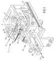
- Figure 1 shows a manipulator 1 such as can be applied in the case of a method and a system according to the invention.
- the manipulator 1 is provided in the vacuum chamber of a SEM that, as a supplement to its standard embodiment, is provided with means for generating a Focused Ion Beam (FIB).
- FIB Focused Ion Beam
- a SEM embodied in this manner is also referred to using the term Dual Beam System.
- the electron beam and the ion beam intersect each other at an angle of circa 52 degrees at the location of a point of coincidence. By positioning an object to be investigated in this point of coincidence, the object to be studied can be processed with the ion beam, which processing can be imaged with the aid of the electron beam.
- the manipulator serves to position the object to be studied in a desired manner with respect to the electron beam and the ion beam.
- the object to be studied is positioned on a table 2 of the manipulator, which forms the extremity of a kinematic system with which table 2 can be moved in five degrees of freedom (three perpendicular translations and two rotations).
- the manipulator 1 comprises a manipulation body 3 that can be translated in two mutually perpendicular directions - depicted by arrows 4, 5 in figure 4 - parallel to the upper surface of the table 2, and can also be rotated about the translation direction 4 as indicated by curved arrow 6, for which purpose the manipulator 1 is provided with a yoke, which is not further depicted.
- table 2 can be adjusted in height above manipulation body 3, as indicated by arrow 7, perpendicular to the plane of table 2, and can be rotated, as indicated by curved arrow 8, about an axis that coincides with the central axis of the disc-like table 2.
- the manipulator 1 is of a so-called eucentric type, which, however, is not necessary within the context of the invention.
- eucentric manipulators an object irradiated by the electron beam and the ion beam remains in focus during rotation according to arrow 6.
- the manipulator 1 described thus far already forms part of the prior art, and is thus well known to the skilled artisan, so that a further elucidation thereof within the context of the current invention can be omitted.
- Characteristic of the invention is, however, that, besides table 2, the manipulator 1 also comprises utilities 9 for positioning a TEM sample holder with a TEM sample attached thereto.
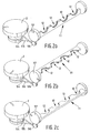
- the utilities 9 comprise an essentially ⁇ -shaped brace 10 that is thus embodied that a TEM sample holder 11 can be connected thereto in a removable manner, which TEM sample holder is schematically depicted in figures 2a to 2c, and 4.
- the TEM sample holder comprises a number of semi-circular hollows 12, which have a groove 13 along their circumferences. These grooves 13 make it possible to insert correspondingly formed semi-circular TEM discs 14 in a clamped manner in the hollows 12.
- the TEM discs 14 are themselves also provided with a series of hollows 15, arranged side-by-side; via a portion of the circumferential edge of these hollows 15, TEM samples 16 are connected to the TEM discs 14 in a manner that will be described later.
- the brace 10 can be rotated about the rotational axis 17.
- Rotational axis 17 is disposed parallel to the rotational axis indicated by curved arrow 6 such that, via rotation about both rotational axis 17 and the rotational axis indicated by curved arrow 6, a relatively large collective rotational range of more than 180 degrees is achieved, so that the TEM samples 16 can be perpendicularly irradiated by the electron beam on opposite sides of the samples.
- brace 10 is rotatable about rotational axis 17 through a maximum of circa 120 degrees, whereas brace 10 can further rotate according to arrow 6 through a maximum angle of 70 degrees.
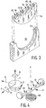
- the manipulation body 3 is provided with a cog 51 that is rotatable about its central axis as a result of being driven by driving means that are not further depicted, whereby the cog 51 is part of a transmission between the driving means and the table 2 for the purpose of rotating the latter.
- the side surface of cog 51 is engaged, at a distance from its central axis, by a driving rod 52, which in turn engages brace 10, at a distance from rotational axis 17, at the position of reference numeral 53.
- the connections between, on the one hand, the driving rod 52, and, on the other hand, the cog 51 and the brace 10, are such that mutual rotation is possible about axes parallel to the rotational axis 17.
- Rotation of cog 51 therefore causes both table 2 to rotate according to curved arrow 8 and brace 10 to rotate about rotational axis 17, the latter occurring back and forth through a rotational range of more than 180 degrees. In this manner, it becomes unnecessary to provide separate transmission and driving means for the special purpose of causing rotation of brace 10 about rotational axis 17, as a result of which brace 10 can, in principle, be added in a simple manner to an existing manipulator according to the prior art.
- FIGS. 2a to 2c further depict the above-described principle in a somewhat different embodiment.
- a circular groove 54 is provided underneath table 2, which groove runs parallel to the upper surface of table 2.
- An endless transmission chord 55 is stretched around a large portion of this groove 54, which chord is also stretched about a round groove in a pressing roller 56.
- This pressing roller 56 presses chord 55 against the outer surface of a disc-like extremity 57 of a TEM sample holder 11, which, as a result hereof, shall rotate together with table 2 about an axis that coincides with the central axis of the disc-like extremity 57.
- a fixed relationship exists between the angular states of the table 2 and the TEM sample holder 11.
- the STEM sample holder 11 Underneath the TEM sample holder 11 is located a STEM detector disc 18 with which it is possible to observe electrons that have radiated through a TEM sample 16. The deflection suffered by these electrons as they radiate through the sample is a measure of the mass of the chemical elements of the TEM sample, and thus gives information on this mass.
- the skilled artisan is already familiar with STEM technology, which therefore does not require further elucidation here.
- the STEM detector disc 18 is carried by a composite carrying arm 19 that can be displaced along guide 20 in the direction of double arrow 21, which extends parallel to the direction indicated by arrow 5.
- the carrying arm 19 is regarded as being part of manipulator 1, it is not rigidly connected to manipulation body 3 thereof, so that, in principle, mutual movement is possible between the manipulation body 3 and the carrying arm 19.
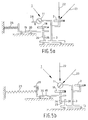
- FIG. 5a the manipulator 1 is located in a first position, whereby the point of coincidence between the electron beam 22 and the ion beam 23 is located just above table 2, at a location where an object to be irradiated by the electron beam 22 and the ion beam 23 shall be positioned on the table 2.
- this first position of the manipulating means 1, and with the aid of the ion beam 23, it is possible in this first position of the manipulating means 1, and with the aid of the ion beam 23, to cut a (crude) TEM sample 16 away from its environment, which is formed by the remaining portion of the object carried on the table 2.
- a stopping stopping contact part 24 of carrying arm 19 is pushed against a stopping contact part 26 of manipulation body 3 as a result of the resilience of the pressing spring 25.
- the manipulator 1 displaces itself to the second position according to figure 5b. During this displacement, the manipulation body 3 and the carrying arm 19 initially move collectively, due to the fact that pressing spring 25 forces stopping contact part 24 against stopping contact part 26.
- a further stopping contact part 27 of carrying arm 19 impacts upon a fixed stopping contact part 28, which can be embodied as part of the manipulator arm 1 but which, as a result of its kinematic position, does not move together with manipulation body 3 thereof.
- a certain play 29 arises between the stopping contact parts 24 and 26, which makes it possible, via limited displacement of the manipulation body 3 in the direction indicated by arrow 5 or in a direction opposite thereto, to mutually position, in a desired manner, the TEM sample holder 11 - together, of course, with the various TEM samples 16 - and the STEM detector disc 18.
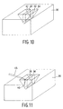
- ion beam 23 is employed to create a perpendicular cutting plane 39 along one side of the cutting planes 31, 32, 33, 34, the cutting plane 39 having an upper cutting edge 40 that extends perpendicular to the cutting edges 35, 36, 37, 38.
- perpendicular cutting planes 41, 42, with respective upper cutting edges 43, 44 are respectively created (figure 10) between cutting plane 31 and 33 and between cutting plane 32 and 34.
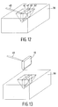
- a probe 45 which in figure 11 and subsequent figures is transparently depicted, is attached via metal deposition to material 30, at the side of the cutting edge 40 between the cutting edges 35 and 36.
- This TEM sample 16 is lifted out of the material 30 with the aid of the probe 45, after which manipulator 1 displaces itself from the first position to the second position, as already set forth on the basis of the schematic figures 5a and 5b.
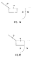
- the TEM sample holder 11 in which the TEM discs 14 have been mounted in a clamped manner, assumes the approximate spatial position that, in the first position of the manipulator 1, was occupied by the table 2 thereof.
- the probe 45 moves the TEM sample 16 against the circumferential edge of one of the hollows 15 in one of the TEM discs 14 (figures 14 and 15).
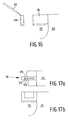
- the TEM sample 16 is attached to this circumferential edge, after which an extremal portion 48 of TEM sample 16, to which extremal portion the probe 45 is attached, is cut off (figure 16). If the TEM sample 16 satisfies the requirements for further investigation with the aid of the STEM detector disc 18, then such analysis can be performed immediately subsequent to the processing steps described heretofore. However, even if this were not the case, it is still possible as a supplementary step to further process the TEM sample 16 whilst attached to the TEM disc 14, principally by irradiation with an ion beam 23 so as to thin the sample, e.g.
Landscapes
- Chemical & Material Sciences (AREA)
- Analytical Chemistry (AREA)
- Physics & Mathematics (AREA)
- Health & Medical Sciences (AREA)
- Life Sciences & Earth Sciences (AREA)
- Biochemistry (AREA)
- General Health & Medical Sciences (AREA)
- General Physics & Mathematics (AREA)
- Immunology (AREA)
- Pathology (AREA)
- Analysing Materials By The Use Of Radiation (AREA)
- Sampling And Sample Adjustment (AREA)
Applications Claiming Priority (2)
| Application Number | Priority Date | Filing Date | Title |
|---|---|---|---|
| NL1022426A NL1022426C2 (nl) | 2003-01-17 | 2003-01-17 | Werkwijze voor het vervaardigen en transmissief bestralen van een preparaat alsmede deeltjes optisch systeem. |
| NL1022426 | 2003-01-17 |
Publications (3)
| Publication Number | Publication Date |
|---|---|
| EP1443541A2 true EP1443541A2 (fr) | 2004-08-04 |
| EP1443541A3 EP1443541A3 (fr) | 2004-08-25 |
| EP1443541B1 EP1443541B1 (fr) | 2008-12-10 |
Family
ID=32653375
Family Applications (1)
| Application Number | Title | Priority Date | Filing Date |
|---|---|---|---|
| EP04000400A Revoked EP1443541B1 (fr) | 2003-01-17 | 2004-01-10 | Procédé de préparation et d'irradiation transmissive d'un échantillon et système optique à faisceau de particules |
Country Status (5)
| Country | Link |
|---|---|
| US (1) | US6963068B2 (fr) |
| EP (1) | EP1443541B1 (fr) |
| JP (1) | JP2004228076A (fr) |
| DE (1) | DE602004018207D1 (fr) |
| NL (1) | NL1022426C2 (fr) |
Cited By (7)
| Publication number | Priority date | Publication date | Assignee | Title |
|---|---|---|---|---|
| WO2005033650A2 (fr) * | 2003-09-17 | 2005-04-14 | Carl Zeiss Nts Gmbh | Procede de preparation d'un echantillon pour examens au microscope electronique, et porte-echantillon et support de transport utilises a cet effet |
| EP1696219A1 (fr) * | 2005-02-23 | 2006-08-30 | FEI Company | Broyage circonférentiel répétitif pour la préparation d échantillons |
| EP1782435A4 (fr) * | 2004-07-28 | 2010-06-16 | Omniprobe Inc | Procede et appareil destines au remplacement in-situ de pointe de sonde a l'interieur d'un microscope a faisceau de particules chargees |
| US8247785B2 (en) | 2007-06-06 | 2012-08-21 | Carl Zeiss Nts Gmbh | Particle beam device and method for use in a particle beam device |
| EP2765591A1 (fr) * | 2013-02-08 | 2014-08-13 | FEI Company | Étage de préparation d'échantillon |
| US9455120B2 (en) | 2011-01-12 | 2016-09-27 | Carl Zeiss Microscopy Gmbh | Particle beam device and method for processing and/or analyzing a sample |
| EP4318545A3 (fr) * | 2022-07-15 | 2024-03-20 | Jeol Ltd. | Support de traitement d'échantillon et procédé de traitement d'échantillon |
Families Citing this family (43)
| Publication number | Priority date | Publication date | Assignee | Title |
|---|---|---|---|---|
| NL1022426C2 (nl) | 2003-01-17 | 2004-07-26 | Fei Co | Werkwijze voor het vervaardigen en transmissief bestralen van een preparaat alsmede deeltjes optisch systeem. |
| US20060219919A1 (en) * | 2003-11-11 | 2006-10-05 | Moore Thomas M | TEM sample holder and method of forming same |
| DE102004036441B4 (de) * | 2004-07-23 | 2007-07-12 | Xtreme Technologies Gmbh | Vorrichtung und Verfahren zum Dosieren von Targetmaterial für die Erzeugung kurzwelliger elektromagnetischer Strahlung |
| JP4664041B2 (ja) * | 2004-10-27 | 2011-04-06 | 株式会社日立ハイテクノロジーズ | 荷電粒子ビーム装置及び試料作製方法 |
| US7208724B2 (en) * | 2004-11-03 | 2007-04-24 | Omniprobe, Inc. | Apparatus and method of detecting probe tip contact with a surface |
| WO2006050495A2 (fr) | 2004-11-03 | 2006-05-11 | Omniprobe, Inc. | Procede et dispositif pour mettre en oeuvre un procede automatise d'extraction in situ |
| JP4185062B2 (ja) * | 2005-03-04 | 2008-11-19 | エスアイアイ・ナノテクノロジー株式会社 | 加工用ステージ及び集束ビーム加工装置並びに集束ビーム加工方法 |
| JP4596968B2 (ja) | 2005-05-11 | 2010-12-15 | 株式会社リコー | 半導体装置の不良箇所観察のためのシリコン基板加工方法及び不良箇所特定方法 |
| EP1780764A1 (fr) * | 2005-11-01 | 2007-05-02 | FEI Company | Ensemble d'étages, appareil d'optique corpusculaire comprenant un tel ensemble d'étages, et procédé de traitement d'un échantillon dans un tel appareil |
| US7511282B2 (en) * | 2006-05-25 | 2009-03-31 | Fei Company | Sample preparation |
| US7423263B2 (en) * | 2006-06-23 | 2008-09-09 | Fei Company | Planar view sample preparation |
| JP4205122B2 (ja) * | 2006-07-19 | 2009-01-07 | 株式会社日立ハイテクノロジーズ | 荷電粒子線加工装置 |
| EP1883095A1 (fr) * | 2006-07-26 | 2008-01-30 | FEI Company | Dispositif de transfert pour transfert d'échantillons |
| US7644637B2 (en) * | 2006-09-25 | 2010-01-12 | Omniprobe, Inc. | Method and apparatus for transfer of samples in a controlled environment |
| WO2008049133A2 (fr) | 2006-10-20 | 2008-04-24 | Fei Company | Procédé de création d'échantillont s/met et structure d'échantillon |
| US8357913B2 (en) | 2006-10-20 | 2013-01-22 | Fei Company | Method and apparatus for sample extraction and handling |
| US7884326B2 (en) * | 2007-01-22 | 2011-02-08 | Fei Company | Manipulator for rotating and translating a sample holder |
| US7834315B2 (en) | 2007-04-23 | 2010-11-16 | Omniprobe, Inc. | Method for STEM sample inspection in a charged particle beam instrument |
| US8835845B2 (en) | 2007-06-01 | 2014-09-16 | Fei Company | In-situ STEM sample preparation |
| JP4691529B2 (ja) | 2007-07-20 | 2011-06-01 | 株式会社日立ハイテクノロジーズ | 荷電粒子線装置、及び試料加工観察方法 |
| EP2051280A1 (fr) * | 2007-10-18 | 2009-04-22 | The Regents of the University of California | Manipulateur motorisé pour positionner un spécimen TEM |
| WO2010014252A2 (fr) * | 2008-08-01 | 2010-02-04 | Omniprobe, Inc. | Support de grille pour analyse au microscope électronique en transmission à balayage dans un instrument à particules chargées |
| DE102008042179B9 (de) | 2008-09-17 | 2013-10-10 | Carl Zeiss Microscopy Gmbh | Verfahren zur Analyse einer Probe |
| DE102008064786B3 (de) | 2008-09-17 | 2023-07-13 | Carl Zeiss Microscopy Gmbh | Verfahren zur Analyse einer Probe |
| DE102009001587A1 (de) * | 2009-01-06 | 2010-07-08 | Carl Zeiss Nts Gmbh | Verfahren zur Einstellung eines Betriebsparameters eines Teilchenstrahlgeräts sowie Probenhalter zur Durchführung des Verfahrens |
| US20110017922A1 (en) * | 2009-07-24 | 2011-01-27 | Omniprobe, Inc. | Variable-tilt tem specimen holder for charged-particle beam instruments |
| JP5753861B2 (ja) * | 2010-03-08 | 2015-07-22 | マイクロスコピー イノベーションズ, エルエルシーMicroscopy Innovations, Llc | 電子顕微鏡グリッドおよび他の材料を担持するためのデバイス |
| DE102011006588A1 (de) * | 2011-03-31 | 2012-10-04 | Carl Zeiss Nts Gmbh | Teilchenstrahlgerät mit Detektoranordnung |
| US8740209B2 (en) * | 2012-02-22 | 2014-06-03 | Expresslo Llc | Method and apparatus for ex-situ lift-out specimen preparation |
| JP6164450B2 (ja) * | 2013-03-11 | 2017-07-19 | 国立大学法人横浜国立大学 | 結晶粒界破壊特性の測定方法、ならびにその測定用試験片およびその製造方法 |
| US9857318B2 (en) | 2013-03-19 | 2018-01-02 | Carl Zeiss Microscopy Gmbh | Method for generating image data relating to an object and particle beam device for carrying out this method |
| US9040908B2 (en) | 2013-06-28 | 2015-05-26 | Fei Company | Plan view sample preparation |
| CN104795302B (zh) | 2013-10-29 | 2018-10-02 | Fei 公司 | 具有用于横切应用的过程自动化的图案识别的差分成像 |
| US10186397B2 (en) * | 2013-11-11 | 2019-01-22 | Howard Hughes Medical Institute | Workpiece holder for workpiece transport apparatus |
| EP2899744A1 (fr) * | 2014-01-24 | 2015-07-29 | Carl Zeiss Microscopy GmbH | Procédé pour préparer et analyser un objet et dispositif à faisceau de particules pour réaliser ledit procédé |
| US9281163B2 (en) | 2014-04-14 | 2016-03-08 | Fei Company | High capacity TEM grid |
| WO2016002719A1 (fr) | 2014-06-30 | 2016-01-07 | 株式会社日立ハイテクサイエンス | Dispositif de préparation automatisée d'échantillons |
| JP2016072089A (ja) | 2014-09-30 | 2016-05-09 | 株式会社日立ハイテクサイエンス | 複合荷電粒子ビーム装置 |
| CZ309656B6 (cs) | 2018-10-10 | 2023-06-21 | Tescan Brno, S.R.O. | Zařízení s alespoň jedním polohovatelným držákem vzorků a způsob změny úhlu náklonu držáku a způsob přípravy lamely |
| US10825646B2 (en) | 2019-03-28 | 2020-11-03 | Fei Company | Actuator-assisted positioning systems and methods |
| US20230126577A1 (en) * | 2020-04-15 | 2023-04-27 | Hitachi High-Tech Corporation | Transfer Device and Analysis System |
| JP7127883B2 (ja) * | 2020-12-04 | 2022-08-30 | 株式会社日立ハイテクサイエンス | 複合荷電粒子ビーム装置 |
| EP4068333A1 (fr) | 2021-03-31 | 2022-10-05 | FEI Company | Support d'échantillon pour une utilisation dans un microscope à particules chargées et procédé d'utilisation d'un tel support d'échantillon dans un tel microscope |
Citations (5)
| Publication number | Priority date | Publication date | Assignee | Title |
|---|---|---|---|---|
| EP0927880A1 (fr) * | 1997-07-22 | 1999-07-07 | Hitachi, Ltd. | Procede et dispositif de preparation d'echantillons |
| US5986264A (en) * | 1995-04-29 | 1999-11-16 | Bal-Tec A.G. | Ion beam preparation device for electron microscopy |
| JP2002062226A (ja) * | 2000-08-18 | 2002-02-28 | Jeol Ltd | Fib試料作製装置 |
| US20020050565A1 (en) * | 2000-11-02 | 2002-05-02 | Hitachi, Ltd. | Method and apparatus for processing a micro sample |
| US20020166976A1 (en) * | 2001-05-08 | 2002-11-14 | Masakazu Sugaya | Beam as well as method and equipment for specimen fabrication |
Family Cites Families (16)
| Publication number | Priority date | Publication date | Assignee | Title |
|---|---|---|---|---|
| US144924A (en) * | 1873-11-25 | Improvement in revolving sample-cases | ||
| US178372A (en) * | 1876-06-06 | Improvement in furnaces for burning sawdust, tan-bark | ||
| JP2774884B2 (ja) * | 1991-08-22 | 1998-07-09 | 株式会社日立製作所 | 試料の分離方法及びこの分離方法で得た分離試料の分析方法 |
| JP3119959B2 (ja) * | 1993-02-05 | 2000-12-25 | セイコーインスツルメンツ株式会社 | 集束イオンビーム装置および加工観察装置 |
| JP3221797B2 (ja) * | 1994-06-14 | 2001-10-22 | 株式会社日立製作所 | 試料作成方法及びその装置 |
| US6188068B1 (en) * | 1997-06-16 | 2001-02-13 | Frederick F. Shaapur | Methods of examining a specimen and of preparing a specimen for transmission microscopic examination |
| US6828566B2 (en) * | 1997-07-22 | 2004-12-07 | Hitachi Ltd | Method and apparatus for specimen fabrication |
| JP3677968B2 (ja) * | 1997-10-01 | 2005-08-03 | 株式会社日立製作所 | 試料解析方法および装置 |
| JP2000035391A (ja) * | 1998-07-16 | 2000-02-02 | Seiko Instruments Inc | 薄片化加工時の試料歪除去方法 |
| WO2000039836A1 (fr) * | 1998-12-29 | 2000-07-06 | Philips Electron Optics B.V. | Microscope electronique a balayage pour fonctionnement en emission avec detecteur reagissant a la localisation |
| DE60144508D1 (de) * | 2000-11-06 | 2011-06-09 | Hitachi Ltd | Verfahren zur Herstellung von Proben |
| JPWO2002075806A1 (ja) * | 2001-03-16 | 2004-07-08 | 株式会社日立製作所 | ウエハの検査方法、集束イオンビーム装置及び透過電子ビーム装置 |
| JP2003007246A (ja) * | 2001-06-22 | 2003-01-10 | Jeol Ltd | 電子顕微鏡 |
| NL1022426C2 (nl) | 2003-01-17 | 2004-07-26 | Fei Co | Werkwijze voor het vervaardigen en transmissief bestralen van een preparaat alsmede deeltjes optisch systeem. |
| US6927400B2 (en) | 2003-03-13 | 2005-08-09 | Ascend Instruments, Llc | Sample manipulation system |
| DE60308482T2 (de) | 2003-04-28 | 2007-06-21 | ICT Integrated Circuit Testing Gesellschaft für Halbleiterprüftechnik mbH | Vorrichtung und Verfahren zur Untersuchung einer Probe eines Spezimen mittels eines Elektronenstrahls |
-
2003
- 2003-01-17 NL NL1022426A patent/NL1022426C2/nl not_active IP Right Cessation
-
2004
- 2004-01-10 DE DE602004018207T patent/DE602004018207D1/de not_active Expired - Lifetime
- 2004-01-10 EP EP04000400A patent/EP1443541B1/fr not_active Revoked
- 2004-01-13 JP JP2004005560A patent/JP2004228076A/ja active Pending
- 2004-01-15 US US10/758,651 patent/US6963068B2/en not_active Expired - Lifetime
Patent Citations (5)
| Publication number | Priority date | Publication date | Assignee | Title |
|---|---|---|---|---|
| US5986264A (en) * | 1995-04-29 | 1999-11-16 | Bal-Tec A.G. | Ion beam preparation device for electron microscopy |
| EP0927880A1 (fr) * | 1997-07-22 | 1999-07-07 | Hitachi, Ltd. | Procede et dispositif de preparation d'echantillons |
| JP2002062226A (ja) * | 2000-08-18 | 2002-02-28 | Jeol Ltd | Fib試料作製装置 |
| US20020050565A1 (en) * | 2000-11-02 | 2002-05-02 | Hitachi, Ltd. | Method and apparatus for processing a micro sample |
| US20020166976A1 (en) * | 2001-05-08 | 2002-11-14 | Masakazu Sugaya | Beam as well as method and equipment for specimen fabrication |
Non-Patent Citations (1)
| Title |
|---|
| PATENT ABSTRACTS OF JAPAN vol. 2002, no. 06, 4 June 2002 (2002-06-04) & JP 2002 062226 A (JEOL LTD), 28 February 2002 (2002-02-28) * |
Cited By (10)
| Publication number | Priority date | Publication date | Assignee | Title |
|---|---|---|---|---|
| WO2005033650A2 (fr) * | 2003-09-17 | 2005-04-14 | Carl Zeiss Nts Gmbh | Procede de preparation d'un echantillon pour examens au microscope electronique, et porte-echantillon et support de transport utilises a cet effet |
| WO2005033650A3 (fr) * | 2003-09-17 | 2005-12-08 | Zeiss Carl Nts Gmbh | Procede de preparation d'un echantillon pour examens au microscope electronique, et porte-echantillon et support de transport utilises a cet effet |
| US7375325B2 (en) | 2003-09-17 | 2008-05-20 | Carl Zeiss Nts Gmbh | Method for preparing a sample for electron microscopic examinations, and sample supports and transport holders used therefor |
| EP1818970A3 (fr) * | 2003-09-17 | 2009-09-16 | Carl Zeiss NTS GmbH | Procédé de préparation d'un échantillon pour des recherches électromicroscopiques tout comme porte-échantillon et support de transport ainsi utilisés |
| EP1782435A4 (fr) * | 2004-07-28 | 2010-06-16 | Omniprobe Inc | Procede et appareil destines au remplacement in-situ de pointe de sonde a l'interieur d'un microscope a faisceau de particules chargees |
| EP1696219A1 (fr) * | 2005-02-23 | 2006-08-30 | FEI Company | Broyage circonférentiel répétitif pour la préparation d échantillons |
| US8247785B2 (en) | 2007-06-06 | 2012-08-21 | Carl Zeiss Nts Gmbh | Particle beam device and method for use in a particle beam device |
| US9455120B2 (en) | 2011-01-12 | 2016-09-27 | Carl Zeiss Microscopy Gmbh | Particle beam device and method for processing and/or analyzing a sample |
| EP2765591A1 (fr) * | 2013-02-08 | 2014-08-13 | FEI Company | Étage de préparation d'échantillon |
| EP4318545A3 (fr) * | 2022-07-15 | 2024-03-20 | Jeol Ltd. | Support de traitement d'échantillon et procédé de traitement d'échantillon |
Also Published As
| Publication number | Publication date |
|---|---|
| EP1443541A3 (fr) | 2004-08-25 |
| NL1022426C2 (nl) | 2004-07-26 |
| US20040144924A1 (en) | 2004-07-29 |
| DE602004018207D1 (de) | 2009-01-22 |
| JP2004228076A (ja) | 2004-08-12 |
| US6963068B2 (en) | 2005-11-08 |
| EP1443541B1 (fr) | 2008-12-10 |
Similar Documents
| Publication | Publication Date | Title |
|---|---|---|
| EP1443541B1 (fr) | Procédé de préparation et d'irradiation transmissive d'un échantillon et système optique à faisceau de particules | |
| JP5208449B2 (ja) | 試料キャリア及び試料ホルダ | |
| JP7340363B2 (ja) | 顕微鏡試料を作製する装置および方法 | |
| US7834315B2 (en) | Method for STEM sample inspection in a charged particle beam instrument | |
| US8487270B2 (en) | Particle beam device and method for use in a particle beam device | |
| EP2413126B1 (fr) | Lamelle TEM et son procédé de fabrication | |
| US20160189929A1 (en) | Rapid tem sample preparation method with backside fib milling | |
| US10629409B2 (en) | Specimen preparation and inspection in a dual-beam charged particle microscope | |
| US10663708B2 (en) | Correlation microscope | |
| EP2558839B1 (fr) | Appareil et procédés de préparation d'échantillons par faisceau d'ions | |
| US8963102B2 (en) | Charged particle beam microscope, sample holder for charged particle beam microscope, and charged particle beam microscopy | |
| US20130146765A1 (en) | Charged Particle Beam Device and Sample Observation Method | |
| JP2004093353A (ja) | 試料作製装置 | |
| US11355310B2 (en) | Method for changing the spatial orientation of a micro-sample in a microscope system, and computer program product | |
| US8759765B2 (en) | Method for processing samples held by a nanomanipulator | |
| US10741360B2 (en) | Method for producing a TEM sample | |
| CN110476220A (zh) | 带电粒子束装置 | |
| WO2022244055A1 (fr) | Porte-échantillon et système d'analyse | |
| Hrnčíř et al. | Variable Angle TEM Grid Holder for Advanced TEM Lamellae Preparation | |
| JP2002319365A (ja) | ステージ及びfib試料作成装置 | |
| CN112166486A (zh) | 用于制作和放置薄片的装置 |
Legal Events
| Date | Code | Title | Description |
|---|---|---|---|
| PUAI | Public reference made under article 153(3) epc to a published international application that has entered the european phase |
Free format text: ORIGINAL CODE: 0009012 |
|
| PUAL | Search report despatched |
Free format text: ORIGINAL CODE: 0009013 |
|
| 17P | Request for examination filed |
Effective date: 20040110 |
|
| AK | Designated contracting states |
Kind code of ref document: A2 Designated state(s): AT BE BG CH CY CZ DE DK EE ES FI FR GB GR HU IE IT LI LU MC NL PT RO SE SI SK TR |
|
| AX | Request for extension of the european patent |
Extension state: AL LT LV MK |
|
| AK | Designated contracting states |
Kind code of ref document: A3 Designated state(s): AT BE BG CH CY CZ DE DK EE ES FI FR GB GR HU IE IT LI LU MC NL PT RO SE SI SK TR |
|
| AX | Request for extension of the european patent |
Extension state: AL LT LV MK |
|
| AKX | Designation fees paid |
Designated state(s): DE FR GB NL |
|
| RBV | Designated contracting states (corrected) |
Designated state(s): DE FR GB NL |
|
| 17Q | First examination report despatched |
Effective date: 20071009 |
|
| GRAP | Despatch of communication of intention to grant a patent |
Free format text: ORIGINAL CODE: EPIDOSNIGR1 |
|
| GRAS | Grant fee paid |
Free format text: ORIGINAL CODE: EPIDOSNIGR3 |
|
| GRAA | (expected) grant |
Free format text: ORIGINAL CODE: 0009210 |
|
| AK | Designated contracting states |
Kind code of ref document: B1 Designated state(s): DE FR GB NL |
|
| REG | Reference to a national code |
Ref country code: GB Ref legal event code: FG4D |
|
| REF | Corresponds to: |
Ref document number: 602004018207 Country of ref document: DE Date of ref document: 20090122 Kind code of ref document: P |
|
| PG25 | Lapsed in a contracting state [announced via postgrant information from national office to epo] |
Ref country code: NL Free format text: LAPSE BECAUSE OF FAILURE TO SUBMIT A TRANSLATION OF THE DESCRIPTION OR TO PAY THE FEE WITHIN THE PRESCRIBED TIME-LIMIT Effective date: 20081210 |
|
| NLV1 | Nl: lapsed or annulled due to failure to fulfill the requirements of art. 29p and 29m of the patents act | ||
| PLBI | Opposition filed |
Free format text: ORIGINAL CODE: 0009260 |
|
| 26 | Opposition filed |
Opponent name: CARL ZEISS NTS GMBH Effective date: 20090907 |
|
| PLAX | Notice of opposition and request to file observation + time limit sent |
Free format text: ORIGINAL CODE: EPIDOSNOBS2 |
|
| REG | Reference to a national code |
Ref country code: FR Ref legal event code: ST Effective date: 20091030 |
|
| PLBB | Reply of patent proprietor to notice(s) of opposition received |
Free format text: ORIGINAL CODE: EPIDOSNOBS3 |
|
| PG25 | Lapsed in a contracting state [announced via postgrant information from national office to epo] |
Ref country code: FR Free format text: LAPSE BECAUSE OF NON-PAYMENT OF DUE FEES Effective date: 20090210 |
|
| PLAB | Opposition data, opponent's data or that of the opponent's representative modified |
Free format text: ORIGINAL CODE: 0009299OPPO |
|
| REG | Reference to a national code |
Ref country code: DE Ref legal event code: R103 Ref document number: 602004018207 Country of ref document: DE Ref country code: DE Ref legal event code: R064 Ref document number: 602004018207 Country of ref document: DE |
|
| R26 | Opposition filed (corrected) |
Opponent name: CARL ZEISS NTS GMBH Effective date: 20090907 |
|
| RDAF | Communication despatched that patent is revoked |
Free format text: ORIGINAL CODE: EPIDOSNREV1 |
|
| RDAG | Patent revoked |
Free format text: ORIGINAL CODE: 0009271 |
|
| STAA | Information on the status of an ep patent application or granted ep patent |
Free format text: STATUS: PATENT REVOKED |
|
| 27W | Patent revoked |
Effective date: 20111123 |
|
| GBPR | Gb: patent revoked under art. 102 of the ep convention designating the uk as contracting state |
Effective date: 20111123 |
|
| PGFP | Annual fee paid to national office [announced via postgrant information from national office to epo] |
Ref country code: DE Payment date: 20120127 Year of fee payment: 9 |
|
| PGFP | Annual fee paid to national office [announced via postgrant information from national office to epo] |
Ref country code: GB Payment date: 20120126 Year of fee payment: 9 |
|
| REG | Reference to a national code |
Ref country code: DE Ref legal event code: R107 Ref document number: 602004018207 Country of ref document: DE Effective date: 20120726 |