WO2022244055A1 - Porte-échantillon et système d'analyse - Google Patents
Porte-échantillon et système d'analyse Download PDFInfo
- Publication number
- WO2022244055A1 WO2022244055A1 PCT/JP2021/018607 JP2021018607W WO2022244055A1 WO 2022244055 A1 WO2022244055 A1 WO 2022244055A1 JP 2021018607 W JP2021018607 W JP 2021018607W WO 2022244055 A1 WO2022244055 A1 WO 2022244055A1
- Authority
- WO
- WIPO (PCT)
- Prior art keywords
- sample
- holder
- holder shaft
- rotation
- shaft
- Prior art date
Links
- 230000007246 mechanism Effects 0.000 claims abstract description 86
- 238000003860 storage Methods 0.000 claims description 80
- 238000002360 preparation method Methods 0.000 claims description 53
- 230000005540 biological transmission Effects 0.000 claims description 43
- 238000010884 ion-beam technique Methods 0.000 claims description 25
- 238000010894 electron beam technology Methods 0.000 claims description 21
- 238000000034 method Methods 0.000 claims description 19
- 230000001678 irradiating effect Effects 0.000 claims description 18
- 239000002245 particle Substances 0.000 claims description 10
- 230000008569 process Effects 0.000 claims description 10
- 238000007789 sealing Methods 0.000 claims description 8
- 238000013459 approach Methods 0.000 claims description 2
- 238000012545 processing Methods 0.000 description 11
- 230000008859 change Effects 0.000 description 7
- 230000008021 deposition Effects 0.000 description 7
- 238000010586 diagram Methods 0.000 description 7
- 150000002500 ions Chemical class 0.000 description 6
- 238000006243 chemical reaction Methods 0.000 description 5
- 230000004048 modification Effects 0.000 description 5
- 238000012986 modification Methods 0.000 description 5
- 230000003287 optical effect Effects 0.000 description 4
- 239000013078 crystal Substances 0.000 description 3
- 238000001514 detection method Methods 0.000 description 2
- 230000000694 effects Effects 0.000 description 2
- 238000005516 engineering process Methods 0.000 description 2
- 230000002452 interceptive effect Effects 0.000 description 2
- 239000000463 material Substances 0.000 description 2
- 230000007704 transition Effects 0.000 description 2
- HBBGRARXTFLTSG-UHFFFAOYSA-N Lithium ion Chemical compound [Li+] HBBGRARXTFLTSG-UHFFFAOYSA-N 0.000 description 1
- 206010061876 Obstruction Diseases 0.000 description 1
- 230000004075 alteration Effects 0.000 description 1
- 239000000470 constituent Substances 0.000 description 1
- 238000012937 correction Methods 0.000 description 1
- 230000007423 decrease Effects 0.000 description 1
- 238000013461 design Methods 0.000 description 1
- 230000006866 deterioration Effects 0.000 description 1
- 238000011161 development Methods 0.000 description 1
- 230000007613 environmental effect Effects 0.000 description 1
- 238000011156 evaluation Methods 0.000 description 1
- 238000005286 illumination Methods 0.000 description 1
- 229910001416 lithium ion Inorganic materials 0.000 description 1
- 229910052751 metal Inorganic materials 0.000 description 1
- 239000002184 metal Substances 0.000 description 1
- 230000001681 protective effect Effects 0.000 description 1
- 239000000126 substance Substances 0.000 description 1
- 238000003325 tomography Methods 0.000 description 1
Images


Classifications
-
- H—ELECTRICITY
- H01—ELECTRIC ELEMENTS
- H01J—ELECTRIC DISCHARGE TUBES OR DISCHARGE LAMPS
- H01J37/00—Discharge tubes with provision for introducing objects or material to be exposed to the discharge, e.g. for the purpose of examination or processing thereof
- H01J37/02—Details
- H01J37/20—Means for supporting or positioning the objects or the material; Means for adjusting diaphragms or lenses associated with the support
-
- H—ELECTRICITY
- H01—ELECTRIC ELEMENTS
- H01J—ELECTRIC DISCHARGE TUBES OR DISCHARGE LAMPS
- H01J2237/00—Discharge tubes exposing object to beam, e.g. for analysis treatment, etching, imaging
- H01J2237/20—Positioning, supporting, modifying or maintaining the physical state of objects being observed or treated
- H01J2237/202—Movement
-
- H—ELECTRICITY
- H01—ELECTRIC ELEMENTS
- H01J—ELECTRIC DISCHARGE TUBES OR DISCHARGE LAMPS
- H01J2237/00—Discharge tubes exposing object to beam, e.g. for analysis treatment, etching, imaging
- H01J2237/30—Electron or ion beam tubes for processing objects
- H01J2237/317—Processing objects on a microscale
- H01J2237/3174—Etching microareas
- H01J2237/31745—Etching microareas for preparing specimen to be viewed in microscopes or analyzed in microanalysers
-
- H—ELECTRICITY
- H01—ELECTRIC ELEMENTS
- H01J—ELECTRIC DISCHARGE TUBES OR DISCHARGE LAMPS
- H01J2237/00—Discharge tubes exposing object to beam, e.g. for analysis treatment, etching, imaging
- H01J2237/30—Electron or ion beam tubes for processing objects
- H01J2237/317—Processing objects on a microscale
- H01J2237/31749—Focused ion beam
-
- Y—GENERAL TAGGING OF NEW TECHNOLOGICAL DEVELOPMENTS; GENERAL TAGGING OF CROSS-SECTIONAL TECHNOLOGIES SPANNING OVER SEVERAL SECTIONS OF THE IPC; TECHNICAL SUBJECTS COVERED BY FORMER USPC CROSS-REFERENCE ART COLLECTIONS [XRACs] AND DIGESTS
- Y02—TECHNOLOGIES OR APPLICATIONS FOR MITIGATION OR ADAPTATION AGAINST CLIMATE CHANGE
- Y02E—REDUCTION OF GREENHOUSE GAS [GHG] EMISSIONS, RELATED TO ENERGY GENERATION, TRANSMISSION OR DISTRIBUTION
- Y02E60/00—Enabling technologies; Technologies with a potential or indirect contribution to GHG emissions mitigation
- Y02E60/10—Energy storage using batteries
Definitions
- the present invention relates to a sample holder and an analysis system, and more particularly to a sample holder provided with a mounting portion on which a sample can be placed at the tip of the holder shaft, and an analysis system including the sample holder.
- a sample for crystal structure observation is prepared by a sample preparation device such as a focused ion beam (FIB) device or an FIB-SEM (Focused Ion Beam-Scanning Electron Microscope) device, and a transmission electron microscope ( A specimen is observed using a specimen observation apparatus such as a TEM (Transmission Electron Microscope).
- a sample preparation device such as a focused ion beam (FIB) device or an FIB-SEM (Focused Ion Beam-Scanning Electron Microscope) device
- a transmission electron microscope A specimen is observed using a specimen observation apparatus such as a TEM (Transmission Electron Microscope).
- Patent Document 1 discloses a function that realizes sample preparation by FIB processing and sample observation by TEM with a single sample holder without changing the sample.
- the sample by transmitting the rotation of the holder shaft through a gear mechanism, the sample can be rotated 360 degrees around an arbitrary rotation axis (Azimuth axis) perpendicular to the extending direction of the holder shaft. .
- Patent Document 2 discloses a technique for forming an airtight chamber in the vicinity of the sample stage by storing the tip of the support rod inside the sample holder by means of a mechanism for sliding the support rod. According to this, FIB processing and TEM observation can be realized with a single sample holder without replacing the sample and without exposing the sample to the atmosphere.
- Patent Documents 1 and 2 it is assumed that the sample is needle-shaped, but it is not assumed that a mesh or half mesh with a diameter of 3 mm, which is usually used in FIB processing and TEM observation, is placed on the sample holder. not This presupposes the preparation of samples with special shapes, special applications such as tomography, or the use of specific meshes. At this time, if an attempt is made to place a large sample including a mesh of a normal size on a single sample holder, the narrowness of the pole piece gap into which the tip of the sample holder is inserted becomes a problem in TEM observation.
- Patent document 2 has a cylindrical storage part, but even if a mesh with a diameter of 3 mm is to be placed on the sample holder, the diameter of the storage part exceeds at least 3 mm. Therefore, in TEM observation, there arises a problem that the sample holder cannot be inserted into the pole piece gap which is, for example, 3 mm or less.
- the distance of the pole piece gap is determined by the design of the magnetic lens and optics. Improvements in aberration correction technology are easing the need to shorten the pole piece gap distance. Therefore, the problem of whether it is possible to mount a large sample on the sample holder and to perform the operation according to the application may continue to occur in the future.
- the position where the sample is placed must be in the direction of the pole piece gap, that is, the direction of the light beam. It should be a thin flat plate in the direction along the axis. Similarly, the member forming the periphery of the sample placement section also needs to be thin in the shape of a flat plate in the direction along the optical axis.
- a sample holder that is normally used has a rotation direction (Tilt rotation direction) with the extending direction of the holder axis as a rotation axis (Tilt axis), and a rotation axis (Azimuth axis) that intersects the holder axis. It can rotate in two directions (Azimuth rotation direction).
- the sample can be stored regardless of the state of the sample rotated in the Azimuth rotation direction (the tilted state of the sample).
- the constituent members including the needle-shaped sample are all housed inside the cylinder, and part of the sample does not protrude outside the cylinder in a specific rotating state. That is, it was possible to store the sample in the storage section in any rotational state.
- a sample holder that can mount a mesh with a diameter of 3 mm is desirable without using a special sample shape or special purpose mesh.
- the mounting section will interfere with the storage section. Therefore, it is necessary to provide a structure in which the mounting section can rotate in the Azimuth rotation direction (the mounting section can be tilted) and to prevent the mounting section from interfering with the storage section during the sample storage operation.
- the main purpose of the present application is to provide a highly versatile sample holder that can be shared by a sample preparation device such as an FIB device or FIB-SEM device and a sample observation device such as a TEM.
- a sample preparation device such as an FIB device or FIB-SEM device
- a sample observation device such as a TEM.
- a technology is provided in which a plate-shaped mounting section on which a large sample or a mesh on which a sample is mounted can be rotated in the Tilt rotation direction and the Azimuth rotation direction.
- a technique is provided in which the placement section can be stored inside the storage section so that the placement section does not interfere with the storage section.
- the present invention provides a technique that can be used in a sample preparation device and a sample observation device without exposing the sample to the atmosphere.
- a sample holder in one embodiment is used in a charged particle beam device. Further, the sample holder includes a holder shaft extending in a first direction, a mounting portion provided at the tip of the holder shaft on which the sample can be placed, and moving the holder shaft in the first direction. a moving mechanism for rotating the holder shaft in a first rotating direction with the center of the holder shaft in a cross-sectional view perpendicular to the first direction as a rotation axis; and a rotating mechanism that intersects with the first direction.
- the guide portion is provided with a first through-hole and a second through-hole communicating with the first through-hole, and the width of the first through-hole in the first rotation direction is equal to the width of the first through-hole. It is larger than the width of the second through-hole in the direction of rotation, and the protrusion is movable inside the first through-hole and inside the second through-hole.
- a sample holder in one embodiment is used in a charged particle beam device.
- the sample holder includes a holder shaft extending in a first direction, a mounting portion provided at the tip of the holder shaft and having a first surface for mounting the sample, and a movement mechanism for moving the holder shaft; a rotation mechanism for rotating the holder shaft in a first rotation direction with the center of the holder shaft in a cross-sectional view perpendicular to the first direction as a rotation axis; a rotating shaft member extending in a third direction intersecting the first direction and fixed to the mounting portion.
- the mounting portion is provided at the distal end of the holder shaft via a transmission member, and an elastic member is provided at the distal end of the holder shaft so as to press the mounting portion against the transmission member.
- the transmission member includes a connection portion fixed to the tip of the holder shaft, and a transmission member extending in the first direction from the connection portion toward the mounting portion and in contact with the first surface. in a cross-sectional view perpendicular to the first direction, the center of the transmitting portion is displaced from the center of the holder shaft, and the mounting portion has a cross-sectional view perpendicular to the third direction. It is rotatable in the second rotation direction with the center of the rotating shaft member as the rotation axis.
- a sample holder in one embodiment is used in a charged particle beam device.
- the sample holder has a holder shaft extending in the first direction, a mounting portion provided at the tip of the holder shaft on which the sample can be placed, and an opening.
- a storage unit capable of storing the mounting unit; a moving mechanism for moving the holder shaft in the first direction; a rotating mechanism for rotating the holder shaft in one rotation direction; and a support.
- the support portion is adjacent to the holder shaft and the placement portion in a third direction that intersects the first direction, and a hatch cover is provided at the tip of the support portion.
- each of the opening and the hatch cover has an elliptical or elliptical shape with the third direction as the major axis.
- a highly versatile sample holder can be provided.
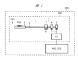
- FIG. 1 is a schematic diagram showing a sample holder, a storage system, and an analysis system according to Embodiment 1.
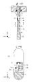
- FIG. 4 is a cross-sectional view showing an open state of the sample holder in Embodiment 1.
- FIG. 4 is a plan view showing an open state of the sample holder in Embodiment 1.
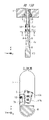
- FIG. 4 is a cross-sectional view showing a stored state of the sample holder in Embodiment 1.
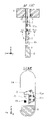
- FIG. 4A and 4B are a side view and a cross-sectional view showing a guide portion and a projecting portion according to Embodiment 1;
- FIG. 4A and 4B are a side view and a cross-sectional view showing a guide portion and a projecting portion according to Embodiment 1;
- FIG. 4A and 4B are a side view and a cross-sectional view showing a guide portion and a projecting portion according to Embodiment 1;
- FIG. 4A and 4B are a side view and a cross-sectional view showing a guide portion and a projecting portion according to Embodiment 1;
- FIG. 4 is a flow chart showing switching between an open state and a retracted state in Embodiment 1.
- FIG. FIG. 2 is a perspective view showing a placement section according to Embodiment 1;
- FIG. 2 is a perspective view showing a placement section according to Embodiment 1;
- FIG. 2 is a cross-sectional view showing a placement section according to Embodiment 1;
- FIG. 4 is a cross-sectional view showing a mesh retainer in Embodiment 1;
- FIG. 2 is a perspective view showing a placement section, a mesh, and a mesh presser according to Embodiment 1;
- FIG. 4 is a cross-sectional view showing the placement section, the mesh, and the mesh presser according to Embodiment 1;
- 2A and 2B are a plan view and a cross-sectional view showing a sample holder according to Embodiment 1;
- FIG. 2A and 2B are a plan view and a cross-sectional view showing a sample holder according to Embodiment 1;
- FIG. 2A and 2B are a plan view and a cross-sectional view showing a sample holder according to Embodiment 1;
- FIG. 1 is a schematic diagram showing a sample preparation apparatus according to Embodiment 1.
- FIG. 1 is a schematic diagram showing a sample observation device according to Embodiment 1.
- FIG. 2 is a cross-sectional view showing a state in which a sample is irradiated with an ion beam according to Embodiment 1; 3 is a cross-sectional view showing a state in which a sample is irradiated with an electron beam in Embodiment 1.
- FIG. 4 is a flow chart showing sample preparation means and sample observation means in Embodiment 1.
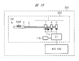
- FIG. 10 is a schematic diagram showing a sample holder, a storage system and an analysis system in a modified example; It is a flowchart which shows the switching from an open state to a storage state in a modification. It is a flowchart which shows the switching from a stored state to an open state in a modification.
- FIG. 8A and 8B are a side view and a cross-sectional view showing a holder shaft and a projecting portion according to Embodiment 2;
- FIG. 8A and 8B are a side view and a cross-sectional view showing a holder shaft and a projecting portion according to Embodiment 2;
- FIG. 8A and 8B are a side view and a cross-sectional view showing a holder shaft and a projecting portion according to Embodiment 2;
- the X-, Y-, and Z-directions described in this application are used to describe the orientation of each configuration of the sample holder, cross each other, and are orthogonal to each other. Also, hereinafter, viewing a plane formed by the X direction and the Y direction from the Z direction may be described as a plan view.
- FIG. 1 is a schematic diagram showing a sample holder 100 , a storage system 200 using the sample holder 100 , and an analysis system 300 including the storage system 200 .
- a sample holder 100 is used in a charged particle beam device, and includes a storage section 1, a holder shaft 2, a mounting section 3, a moving mechanism 4, a rotating mechanism 5, a protruding section 6, and a guide section 7. .
- the storage section 1 can store the placement section 3 therein when the holder shaft 2 is moved. Further, the moving mechanism 4 , the rotating mechanism 5 , the projecting portion 6 and the guide portion 7 are provided inside the storage portion 1 .
- the holder shaft 2 extends in the first direction (X direction) and is connected to the moving mechanism 4 and the rotating mechanism 5 .
- a mounting portion 3 on which the sample SAM can be mounted is provided at the tip of the holder shaft 2 .
- the movement mechanism 4 is a mechanism for moving the holder shaft 2 in the X direction
- the rotation mechanism 5 is a mechanism for rotating the holder shaft 2 in the first rotation direction.
- the first rotation direction is a rotation direction with the center of the holder shaft 2 as the rotation axis in a cross-sectional view perpendicular to the extending direction (X direction) of the holder shaft 2 . Details of the projecting portion 6 and the guide portion 7 will be described later with reference to FIGS. 5A to 5C.
- the control unit C1 is electrically connected to the moving mechanism 4 and the rotating mechanism 5 and controls their operations. That is, the movement of the holder shaft 2 in the X direction and the rotation of the holder shaft 2 in the first rotation direction are controlled by the controller C1. The operator can directly operate the moving mechanism 4 or the rotating mechanism 5 to move and rotate the holder shaft 2 without using the control unit C1.
- the storage system 200 includes the sample holder 100 and the controller C1, and is applicable to the sample preparation device 400 and the sample observation device 500.
- the controller C1 can be configured as a part of the sample preparation device 400 or a part of the sample observation device 500 .
- the analysis system 300 includes a storage system 200 (sample holder 100), a sample preparation device 400, and a sample observation device 500, and a single sample holder 100 can be used to process the sample SAM and observe the sample SAM.
- FIG. 2 to 4 show an enlarged view of the mounting portion 3 of the sample holder 100.
- FIG. 2 and 3 show an open state in which the holder shaft 2 moves in the X direction and the placement section 3 is positioned outside the storage section 1.
- FIG. FIG. 4 shows a stored state in which the holder shaft 2 moves in the X direction and the placement section 3 is stored inside the storage section 1 .
- the expression "open state” or “storage state” it means that the placement section 3 is in the state described above.
- the sample holder 100 further includes a support portion 8 extending in the first direction (X direction).
- the support portion 8 can move in the X direction in conjunction with movement of the holder shaft 2 by the moving mechanism 4 .
- the support portion 8 is adjacent to the holder shaft 2 and the mounting portion 3 in a third direction (Z direction) intersecting the first direction (X direction).
- the supporting portion 8 has a structure in which one side is opened so as not to obstruct ion beam irradiation during processing by the sample preparation apparatus 400 .
- the support portion 8 exists below the holder shaft 2 and the mounting portion 3 but does not exist above the holder shaft 2 and the mounting portion 3 .
- the sample holder 100 further includes a rotating shaft member 9 extending in the third direction (Z direction) and fixed to the mounting section 3 .
- the rotary shaft member 9 is fitted inside the hole provided in the support portion 8 to such an extent that the rotary shaft member 9 can rotate in the second rotation direction. That is, the mounting portion 3 is attached to the support portion 8 by the rotary shaft member 9 . Attachment of the rotation shaft member 9 to the support portion 8 is not particularly limited, and for example, a method of fixing the rotation shaft member 9 to the support portion 8 on the side opposite to the mounting portion 3 by screwing may be used.
- the second direction of rotation is the direction of rotation about the center of the rotation shaft member 9 in a cross-sectional view perpendicular to the extending direction (Z direction) of the rotation shaft member 9 as the rotation axis.
- the mounting portion 3 fixed to the rotary shaft member 9 can rotate in the second rotation direction according to the rotation of the rotary shaft member 9 .
- a hatch cover 10 is provided at the tip of the support portion 8.
- the hatch cover 10 is formed to have approximately the same size as the opening 14 of the storage section 1 .
- the opening 14 is closed by the hatch cover 10 in the stowed state.
- a sealing member 15 such as an O-ring is provided in the opening 14 of the storage section 1 .
- the hatch cover 10 is in close contact with the sealing member 15, so that the inside of the storage section 1 is sealed. Thereby, the degree of vacuum inside the storage unit 1 is maintained.
- the mounting portion 3 is provided at the tip of the holder shaft 2 with a transmission member (cam) 12 interposed therebetween.
- An elastic member 13 such as a spring is provided at the tip of the holder shaft 2 so as to press the mounting portion 3 against the transmission member 12 .
- the transmission member 12 has a connection portion 12a and a transmission portion 12b.
- the connecting portion 12 a is fixed to the tip of the holder shaft 2 .
- the transmission portion 12 b extends in the X direction from the connection portion 12 a toward the mounting portion 3 and contacts the mounting portion 3 .
- the transmission member 12, the elastic member 13, and the rotating shaft member 9 can rotate the mounting section 3 in the second rotation direction. Details of these will be described later with reference to FIGS. explain.
- the protruding portion 6 is fixed to the holder shaft 2 so as to protrude in a second direction intersecting the first direction (X direction).
- the second direction may be any direction that intersects the extending direction of the holder shaft 2, and may be the Y direction or the Z direction, or may be a different direction.
- the protrusion 6 rotates when the holder shaft 2 is rotated by the rotating mechanism 5 and moves when the holder shaft 2 is moved by the moving mechanism 4 . That is, the position of the projecting portion 6 is changed according to the rotation and movement of the holder shaft 2 .
- the guide part 7 surrounds the outer periphery of the holder shaft 2 in the first rotation direction and is separated from the holder shaft 2 . Since the guide part 7 is not affected by the movement of the holder shaft 2 , the position of the guide part 7 does not change according to the rotation and movement of the holder shaft 2 .
- the guide portion 7 is provided with a through hole 7a and a through hole 7b communicating with the through hole 7a.
- the width of the through hole 7a in the first rotation direction is larger than the width of the through hole 7b in the first rotation direction.
- the projecting portion 6 can move inside the through hole 7a and inside the through hole 7b.
- FIG. 5A shows the appearance of the projecting portion 6 in the open state.
- the projection 6 moves inside the through hole 7a along the first rotation direction. That is, in the open state, the movement of the projecting portion 6 in the first rotation direction is not restricted, so the holder shaft 2 can rotate in the first rotation direction.
- the holder shaft 2 cannot move in the X direction.
- FIG. 5B shows the state of the projecting portion 6 when switching between the open state and the retracted state.
- the protruding portion 6 moves inside the through hole 7b as the holder shaft 2 is moved by the moving mechanism 4.
- the moving mechanism 4 can be driven only when the holder shaft 2 satisfies a specific rotational state due to the spatial interference between the projecting portion 6 and the guide portion 7 .
- FIG. 5C shows how the projecting portion 6 is in the retracted state.
- the projecting portion 6 moves along the X direction inside the through hole 7b. That is, in the retracted state, the movement of the projecting portion 6 in the X direction is not restricted, so the holder shaft 2 can move in the X direction.
- the holder shaft 2 cannot rotate in the first rotation direction. It should be noted that after the mounting portion 3 is completely stored inside the storage portion 1, the projection portion 6 passes through the guide portion 7, so that the holder shaft 2 can also be rotated in the first rotation direction.
- Steps S1 to S3 shown in FIG. 6 are flowcharts for switching from the stored state to the open state
- steps S4 to S6 shown in FIG. 6 are flowcharts for switching from the open state to the stored state.
- step S1 it is confirmed whether the rotation state of the holder shaft 2 is a specific rotation state. In cases other than the specific rotation state, the rotation mechanism 5 is driven in the retracted state, and the holder shaft 2 is rotated so that the rotation state of the holder shaft 2 becomes the specific rotation state.
- step S2 when it is confirmed that the rotation state of the holder shaft 2 is a specific rotation state, the moving mechanism 4 is driven to move the holder shaft 2 in the X direction, and move the mounting section 3 to the inside of the storage section 1. move out from This movement is performed until the protruding portion 6 reaches a communicating portion between the through holes 7a and 7b. That is, the process transitions from FIG. 5C to FIG. 5B.
- step S3 the sample holder 100 is opened.
- the holder shaft 2 By driving the rotation mechanism 5 from the state of FIG. 5B, the holder shaft 2 can be rotated in the first rotation direction as shown in FIG. 5A.
- step S4 the rotation mechanism 5 is driven in the open state, and the holder shaft 2 is rotated so that the rotation state of the holder shaft 2 becomes a specific rotation state.
- the protruding portion 6 moves to a communicating portion between the through holes 7a and 7b. 5A to 5B.
- step S5 the moving mechanism 4 is driven, the holder shaft 2 is moved in the X direction, and the placement section 3 is moved from the outside to the inside of the storage section 1. 5B to FIG. 5C.
- step S6 the sample holder 100 is put into a retracted state.
- driving of the moving mechanism 4 and driving of the rotating mechanism 5 may be performed by the controller C1 or by an operator.
- Embodiment 1 by using the projecting portion 6 and the guide portion 7, the movement of the holder shaft 2 in the X direction is possible only when the rotation state of the holder shaft 2 is a specific rotation state. Therefore, it is possible to easily switch between the open state and the retracted state.
- FIG. 9 is a cross-sectional view taken along line BB of FIGS. 7 and 8.
- the mounting portion 3 has a flat plate shape whose width in the Y direction is smaller than the width in the X direction and the width in the Z direction. Further, the mounting section 3 is rotatable in the second rotation direction according to the rotation of the rotating shaft member 9 .
- the mounting portion 3 has a first surface (mounting surface) 3a for mounting the sample SAM, and a second surface 3b opposite to the first surface 3a.
- the second surface 3b is provided with a groove 3c having a concave shape extending from the second surface 3b side toward the first surface 3a side, and a groove 3d is provided at a position away from the groove 3c in the X direction.
- the groove 3d is inclined at a constant angle with respect to the second surface 3b, and has a shape that intermittently increases in depth as it approaches the groove 3c. In other words, the groove 3d has such a shape that the thickness between the first surface 3a and the second surface 3b intermittently decreases toward the groove 3c.
- the groove 3c can be mainly used as a guide for the elastic member 13, and the groove 3d can be mainly used when the mounting portion 22 of the mesh retainer 20 is mounted.
- FIG. 10 shows a mesh retainer 20 for placing the mesh 30 on the placing portion 3.
- FIG. 11 and 12 show how the mesh 30 on which the sample SAM is mounted is mounted on the mounting section 3 using the mesh retainer 20.
- FIG. 12 is a cross-sectional view taken along line BB of FIG.
- the mesh retainer 20 has a flat plate-shaped sandwiching portion 21, a hook-shaped mounting portion 22, and a detachable portion 23 bent from the sandwiching portion 21.
- the clamping portion 21, the mounting portion 22, and the detachable portion 23 are integral members made of an elastic member.
- the tip of the fishhook of the mounting portion 22 is structured so as to be inclined at a constant angle with respect to the second surface 3b, and has the same inclination angle as the groove 3d.
- the mesh 30 can mount the sample SAM, is a half mesh with a diameter of about 3 mm, and has one or more micropillars 31 .
- the sample SAM is prepared by the sample preparation device 400 or the like, and attached to the micropillar 31 by deposition.
- the mesh 30 When the mesh 30 is placed on the placement portion 3, the mesh 30 can be inserted between the first surface 3a and the sandwiching portion 21 while fitting the hook-shaped attachment portion 22 into the groove 3d.
- the mesh retainer 20 is fixed to the mounting portion 3 by fitting the tip of the mounting portion 22 into the groove 3d.
- a gap is generated between the first surface 3a and the clamping portion 21. .
- the mesh 30 is inserted into the gap.
- a structure for retaining the mesh 30 without using screws can be realized, so that the structure of each of the mesh retainer 20 and the placement section 3 can be reduced.
- the mesh 30 can be quickly replaced in a short time simply by the operator picking up the attaching/detaching portion 23 .
- the elastic member 13 is provided at the tip of the holder shaft 2 so as to press the mounting portion 3 against the transmission member 12 .
- the transmission member 12 has a connecting portion 12a fixed to the tip of the holder shaft 2 and a transmitting portion 12b extending in the X direction from the connecting portion 12a toward the mounting portion 3. As shown in FIG. In addition, in a cross-sectional view perpendicular to the X direction, the transmission portion 12b has a circular shape.
- the transmission portion 12b contacts the first surface 3a of the mounting portion 3, and the elastic member 13 moves the mounting portion 3 to the transmission member 12 (transmission portion 12b) inside the groove 3c. is pressed against Since the groove 3 c serves as a guide for the elastic member 13 , it is possible to prevent the elastic member 13 from coming off the mounting portion 3 .
- the center of the transmission part 12b is displaced from the center of the holder shaft 2 in a cross-sectional view perpendicular to the first direction (X direction). Therefore, when the holder shaft 2 rotates in the first rotation direction, the transmission part 12b moves in the first rotation direction while drawing a large orbit around the holder shaft 2 with the center of the holder shaft 2 as the rotation axis.
- the contact position between the first surface 3a and the transmission portion 12b changes along the first rotation direction. Due to such movement of the transmitting portion 12b, the placing portion 3 is pushed by the transmitting portion 12b and rotates together with the rotary shaft member 9 in the second rotation direction. Further, the mounting portion 3 is always given a reaction force by the elastic member 13 and is always pressed against the transmission member 12 . In other words, the mounting section 3 follows the movement of the transmission section 12b by the reaction force.
- the transmission member 12 and the elastic member 13 can synchronize the rotation of the holder shaft 2 in the first rotation direction and the rotation of the mounting section 3 in the second rotation direction.
- the structure using these is, in principle, a rotational operation without backlash, and is superior to a rotating mechanism using a gear structure in terms of positional accuracy and the like.
- the groove 3c may be inclined like the groove 3d for the purpose of reducing the change in the reaction force.
- the cross section of the transmission portion 12b may be changed from a circular shape to an elliptical shape.
- the shape of the elastic member 13 may be changed.
- the opening 14 of the storage unit 1 and the hatch cover 10 each have an oval shape or an elliptical shape with the third direction (Z direction) as the major axis.
- a plate-shaped mounting portion 3 having a relatively thin width in the Y direction is used, and the sample SAM is mounted on the first surface 3a using a mesh retainer 20, a mesh 30, and the like. Since the opening 14 has an elliptical shape with the long axis in the Z direction, such a flat plate shape can be accommodated.
- the sealing member 15 In the stored state, the sealing member 15 provided in the opening 14 and the hatch cover 10 are in close contact. Thereby, the airtightness inside the storage unit 1 can be maintained.
- the sealing member 15 is configured by an oval or elliptical O-ring or the like in accordance with the shape of the opening 14 .
- the mounting section 3 when the mounting section 3 rotates, the mounting section 3 protrudes from the support section 8 in the Y direction and does not fit inside the opening 14 of the storage section 1. may disappear. If the placement section 3 is rotated and shifted to the stored state as shown in FIG. That is, when the sample SAM is placed on the placement unit 3 as shown in FIG. 11, the sample SAM may be damaged.
- the holder shaft 2 is brought into a specific rotational state as shown in FIG. 5B.
- the protrusion 6 moves along the X direction inside the through hole 7b, the first surface 3a becomes parallel to the plane defined by the X direction and the Y direction, as shown in FIG. 13A. Therefore, the problem that the mounting section 3 interferes with the storage section 1 can be resolved.
- the holder shaft 2 in the open state, can rotate in the first rotation direction as shown in FIG. 5A, and the placement section 3 can rotate in the second rotation direction as shown in FIGS. 13B and 13C. Therefore, for example, when irradiating the sample SAM with an ion beam in the sample preparation device 400 or when irradiating the sample SAM with an electron beam in the sample observation device 500, the sample SAM can be tilted.
- FIG. 14 is a schematic diagram showing the sample preparation device 400 according to the first embodiment.
- the sample preparation device 400 is composed of a charged particle beam device such as an FIB device, for example.
- the sample preparation device 400 includes a sample chamber 40, an ion source 41, an irradiation lens 42, an aperture 43, a scanning electrode 44, an objective lens 45, a secondary electron detector 46, a deposition gun 47, a microprobe 48 and a controller C2.
- the sample holder 100 is insertable inside the sample chamber 40 .
- the mounting section 3 can mount the processed sample SAM by using a mesh 30 or the like.
- the controller C2 is electrically connected to the ion source 41, the irradiation lens 42, the aperture 43, the scanning electrode 44, the objective lens 45, the secondary electron detector 46, the deposition gun 47 and the microprobe 48, and controls their operations. do.
- the controller C2 is also electrically connected to the controller C3 of the sample observation device 500, and can communicate information with the controller C3.
- a controller C1 that controls each operation of the sample holder 100 is electrically connected to the controller C2 as part of the sample preparation device 400. That is, storage system 200 is included in sample preparation device 400 .
- the sample holder 100 receives instructions from the controller C2 via the controller C1, and each operation of the sample holder 100 is controlled by the controller C2.
- the sample SAM mounted on the mounting section 3 can change the tilt angle on the optical axis of the ion beam IB. Become. Therefore, it is possible to process the sample SAM from various angles.
- the input device 70 and the display 71 are provided inside or outside the sample preparation device 400 or the sample observation device 500, respectively.
- the input device 70 is, for example, a device for an operator to input instructions such as input of analysis target information and change of irradiation conditions of the ion beam IB and the electron beam EB1.
- the input device 70 is, for example, a keyboard or mouse.
- the display 71 is a screen for controlling each configuration of the sample preparation device 400 and the sample observation device 500 . When various instructions are input by the input device 70, the instructions are sent to the controller C2 or the controller C3.
- the ion source 41 can irradiate an ion beam IB.
- An ion beam IB emitted from an ion source 41 is converged by an irradiation lens 42 and an aperture 43, passes through an objective lens 45, and converges on the sample SAM.
- a scanning electrode 44 positioned above the objective lens 45 deflects and scans the ion beam IB incident on the sample SAM according to instructions from the controller C2.
- a secondary electron detector 46 , a deposition gun 47 and a microprobe 48 are attached to the sample chamber 40 above the sample holder 100 .
- the secondary electron detector 46 has a circuit or an arithmetic processing unit that performs arithmetic processing of the secondary electrons as a detection signal and forms an image.
- the gas discharged from the deposition gun 47 toward the sample SAM reacts with the ion beam IB and is decomposed. Then, the metal is deposited as a film on the sample SAM in the ion beam IB irradiation region. This deposited film is used as a protective film for the surface of the sample SAM before processing, and is also used for fixing the micro sample piece to the sample stage. Further, by using the microprobe 48 , the processed sample SAM can be transported to the mounting section 3 of the sample holder 100 .
- FIG. 15 is a schematic diagram showing the sample observation device 500 according to the first embodiment.
- the sample observation device 500 is composed of a charged particle beam device such as a TEM, for example.
- the sample observation device 500 includes a sample chamber 50, an electron source 51, an irradiation lens 52, a scanning coil 53, a holder adapter 54, a secondary electron detector 55, an objective lens 56, a projection lens 57, an annular detector 58, and a detector 59. , a camera 60 and a controller C3.
- the sample holder 100 can be inserted inside the sample chamber 50 by using the holder adapter 54 .
- Controller C3 electrically connects electron source 51, illumination lens 52, scanning coil 53, holder adapter 54, secondary electron detector 55, objective lens 56, projection lens 57, annular detector 58, detector 59 and camera 60. to control these operations.
- the controller C1 that controls each operation of the sample holder 100 is electrically connected to the controller C3 as part of the sample observation device 500. That is, storage system 200 is included in sample observation device 500 .
- the sample holder 100 receives instructions from the controller C3 via the controller C1, and each operation of the sample holder 100 is controlled by the controller C3.
- the sample SAM mounted on the mounting section 3 can change the tilt angle on the optical axis of the electron beam EB1. Become. Therefore, it is possible to observe the sample SAM from various angles.
- the electron source 51 can emit an electron beam EB1.
- a scanning coil 53 is provided between the irradiation lens 52 and the objective lens 56 , and the sample SAM is inserted below the scanning coil 53 .
- a secondary electron detector 55 is provided above the sample SAM and below the scanning coil 53 .
- the secondary electron detector 55 includes a circuit or arithmetic processing unit that performs arithmetic processing of the secondary electrons as a detection signal and forms an image.
- the electron beam EB1 emitted from the electron source 51 is spot-focused on the sample SAM by the irradiation lens 52, and the sample SAM is scanned by the scanning coil 53.
- the secondary electron detector 55 can detect secondary electrons generated from the sample SAM by irradiation with the electron beam EM1 and generate a secondary electron image. Such secondary electron images can be confirmed on the display 71 .
- An annular detector 58 for STEM dark field image observation is arranged below the projection lens 57 .
- a detector 59 (detector for STEM bright-field image observation) that can be moved in and out from the electron beam axis is provided.
- a camera 60 for transmission image observation is arranged below the detector 59 .
- the sample SAM is irradiated with electrons EB1 having a certain spread, and the transmitted electrons EB2 transmitted through the sample SAM are imaged by the objective lens 56, and the image is projected onto the projection lens 57. is magnified by and displayed on the camera 60 .
- Detector 59 can detect transmitted electrons EB2 to produce a bright field transmitted electron image.
- the annular detector 58 can detect electrons (elastically scattered electrons) scattered from the sample SAM by the irradiation of the electron beam EB1 to generate a dark-field transmission electron image.
- the sample SAM By changing the tilt angle of the sample SAM on the optical axis of the electron beam EB1, the sample SAM can be observed from various angles, and secondary electron images, scanning transmission images, and transmission electron images can be observed. . Also, these are stored in the controller C3 as image data.
- FIG. 16 shows how the sample SAM is irradiated with the ion beam IB in the sample preparation device 400
- FIG. 17 shows how the sample SAM is irradiated with the electron beam EB1 in the sample observation device 500.
- observation is performed with the direction of the sample holder 100 perpendicular to that in FIG. 16 in order to use the transmitted electrons EB2 that have passed through the sample SAM.
- sample preparation means provided in the sample preparation apparatus 400 and the sample observation means provided in the sample observation apparatus 500 will be described below with reference to FIG. Steps S11 to S16 shown in FIG. 18 correspond to the sample preparing means, and steps S17 to S19 shown in FIG. 18 correspond to the sample observing means.
- the sample SAM is prepared inside the sample chamber 40 of the sample preparation device 400.
- the sample SAM may be a substance that reacts with or degrades with atmospheric components in the atmosphere.
- the sample SAM may be prepared in a space previously evacuated to prevent deterioration of the structure.
- step S12 the sample holder 100 is inserted into the sample chamber 40 in an open state.
- the method for opening the sample holder 100 is the same as steps S1 to S3 in FIG.
- the sample holder SAM is opened before being inserted into the sample preparation apparatus 400, the airtight state inside the storage section 1 is released, but the air inside the storage section 1 is released from the exhaust system of the sample preparation apparatus 400. can be exhausted by
- step S13 first, the inside of the sample chamber 40 is brought into a high vacuum state.
- the sample SAM is irradiated with the ion beam IB to process a part of the sample SAM.
- the deposition gun 47 and microprobe 48 are used to mount the sample SAM on the mount 3 .
- the mesh 30 is used to attach the sample SAM onto the micropillars 31 on the mesh 30 placed on the placement section 3 .
- the sample SAM may be placed directly on the mesh 30 or the placement section 3.
- step S14 the sample SAM is irradiated with the ion beam IB to further process a portion of the sample SAM.
- the angle between the mounting section 3 and the ion beam IB can be adjusted, and the sample SAM can be processed from various directions.
- step S15 the placement section 3 is stored inside the storage section 1.
- the method of putting the sample holder 100 into the storage state is the same as steps S4 to S6 in FIG.
- the hatch cover 10 and the sealing member 15 are in contact with each other to seal the storage section 1 , so that the inside of the storage section 1 is kept in a high vacuum state similar to the inside of the sample chamber 40 .
- step S ⁇ b>16 the sample holder 100 is taken out from the sample chamber 40 and transported to the sample observation device 500 . At this time, since the sample holder 100 is in the stored state, the inside of the storage unit 1 is kept in a high vacuum state even if the sample holder 100 is taken out into the atmosphere.
- step S17 the sample holder 100 is inserted into the sample chamber 50.
- the sample holder 100 is in the storage state
- the sample SAM processed by the sample preparation apparatus 400 is placed on the mounting section 3, and the mounting section 3 is stored inside the storage section 1. is in a state of Further, the inside of the sample chamber 50 is already in a high vacuum state.
- step S18 the holder shaft 2 is moved in the X direction, and the placement section 3 is moved out of the storage section 1. That is, the sample holder 100 is opened.
- the method for opening the sample holder 100 is the same as steps S1 to S3 in FIG.
- step S19 the sample SAM is irradiated with the electron beam EB1 to observe the sample SAM. Thereby, a secondary electron image, a scanning transmission image, and a transmission electron image can be observed, and image data thereof can be acquired.
- the sample holder 100 of Embodiment 1 can correspond to a flat plate shape, and can be switched between the open state and the retracted state only when the holder shaft 2 is in a specific rotating state. Therefore, the sample preparing means and the sample observing means can be carried out efficiently and reliably. As described above, according to Embodiment 1, it is possible to provide the highly versatile sample holder 100 that can be shared by the sample preparation device 400 and the sample observation device 500 .
- the modified sample holder 100 and storage system 200 further comprises a sensor 11a and a read operation mechanism 11b compared to FIG.
- the sensor 11 a is attached to the holder shaft 2 , positioned near the guide portion 7 and the projecting portion 6 , and provided to detect the position of the projecting portion 6 . That is, the sensor 11a can detect a change in the position of the projecting portion 6 in the first rotation direction.
- the reading operation mechanism 11b is a mechanism for automatically switching between the open state and the retracted state, and is, for example, a button.
- the controller C1 is electrically connected to the sensor 11a and the reading operation mechanism 11b, and can calculate the rotation state of the holder shaft 2 from the position of the projection 6 detected by the sensor 11a.
- the control unit C1 When the operator drives the reading operation mechanism 11b (presses the button), the control unit C1 issues an instruction to the sensor 11a and causes the sensor 11a to detect the position of the projection 6. Next, the controller C1 calculates the rotation state of the holder shaft 2 from the position of the projecting portion 6. FIG. Next, the control unit C1 issues an instruction to the rotation mechanism 5 so that the protruding part 6 can move inside the through hole 7b (so that the rotation state of the holder shaft 2 becomes a specific rotation state). , the rotating mechanism 5 rotates the holder shaft 2 . After that, the controller C1 issues an instruction to the moving mechanism 4, and causes the moving mechanism 4 to move the holder shaft 2 in the X direction. In this manner, switching between the open state and the retracted state can be performed automatically.
- the control unit C1 stores in advance information as to what position the projection 6 should be placed in to bring the holder shaft 2 into a specific rotational state.
- the control unit C1 may be responsible for driving the reading operation mechanism 11b.
- the control unit C1 may be responsible for driving the reading operation mechanism 11b.
- a GUI corresponding to the reading operation mechanism 11b may be displayed on the display 71 and operated by the operator.
- the controller C2 or the controller C3 issues an instruction to the sensor 11a via the control section C1 to detect the position of the protruding section 6 by the sensor 11a.
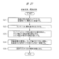
- FIGS. 20 and 21 are flowcharts performed using the sensor 11a and the reading operation mechanism 11b, and are flowcharts showing switching between the open state and the retracted state.
- Steps S21 to S25 shown in FIG. 20 are a flowchart for switching from the stored state to the open state.
- Steps S26 to S30 shown in FIG. 21 are a flowchart for switching from the open state to the retracted state.
- step S21 the sample holder 100 in the stored state is electrically connected to the controller C1. This enables control of the moving mechanism 4, the rotating mechanism 5, the sensor 11a, and the reading operation mechanism 11b by the controller C1.
- step S22 an opening command is output to the sensor 11a by operating the reading operation mechanism 11b or by the control section C1.
- step S23 the position of the projecting portion 6 is detected by the sensor 11a.
- the rotation state of the holder shaft 2 is calculated from the position of the projecting portion 6 by the controller C1.
- the rotation mechanism 5 is driven to rotate the holder shaft 2 so that the rotation state of the holder shaft 2 becomes the specific rotation state.
- the signal from the sensor 11a may be read again by the controller C1 to check the position of the projecting portion 6.
- step S24 when it is confirmed that the rotation state of the holder shaft 2 is in the specific rotation state, the moving mechanism 4 is driven to move the holder shaft 2 in the X direction, and move the placement section 3 to the inside of the storage section 1. move out from This movement is performed until the protruding portion 6 reaches a communicating portion between the through holes 7a and 7b. That is, the process transitions from FIG. 5C to FIG. 5B.
- step S25 the sample holder 100 is opened.
- the holder shaft 2 By driving the rotation mechanism 5 from the state of FIG. 5B, the holder shaft 2 can be rotated in the first rotation direction as shown in FIG. 5A.
- step S26 the open sample holder 100 is electrically connected to the controller C1. This enables control of the moving mechanism 4, the rotating mechanism 5, the sensor 11a, and the reading operation mechanism 11b by the controller C1.
- step S27 a storage command is output to the sensor 11a by operating the reading operation mechanism 11b or by the control unit C1.
- step S28 the position of the projecting portion 6 is detected by the sensor 11a.
- the rotation state of the holder shaft 2 is calculated from the position of the projecting portion 6 by the controller C1.
- the rotation mechanism 5 is driven to rotate the holder shaft 2 so that the rotation state of the holder shaft 2 becomes the specific rotation state.
- the signal from the sensor 11a may be read again by the controller C1 to check the position of the projecting portion 6.
- step S29 when it is confirmed that the rotation state of the holder shaft 2 is the specific rotation state, the moving mechanism 4 is driven to move the holder shaft 2 in the X direction, and the placement section 3 is moved to the outside of the storage section 1. move inward from 5B to FIG. 5C.
- step S30 the sample holder 100 is put into a stored state.
- Embodiment 2 (Embodiment 2) Embodiment 2 will be described below with reference to FIGS. 22A to 22C. In the following, differences from Embodiment 1 will be mainly described, and descriptions of points that overlap with Embodiment 1 will be omitted.
- the projecting portion 6 is fixed to the holder shaft 2, and the guide portion 7 is provided with the through holes 7a and 7b.
- recessed portion 2a and recessed portion 2b are provided on holder shaft 2
- projection portion 6 is provided at a position spaced apart from holder shaft 2
- guide portion 7 Fixed the projecting portion 6 extends in a direction (second direction) intersecting the extending direction (first direction) of the holder shaft 2 .
- the recess 2a communicates with the recess 2b, and the width of the recess 2a in the first rotation direction is larger than the width of the recess 2b in the first rotation direction.
- Embodiment 2 not only the position of the guide portion 7 but also the position of the projecting portion 6 are not changed according to the rotation and movement of the holder shaft 2 .
- the position of the recess 2a and the position of the recess 2b are changed as the holder shaft 2 rotates and moves.
- FIG. 22A shows how the holder shaft 2 and the projecting portion 6 are in the open state.
- the holder shaft 2 When the holder shaft 2 is rotated by the rotation mechanism 5, the holder shaft 2 can be rotated along the first rotation direction with the projection 6 fitted inside the recess 2a. On the other hand, the holder shaft 2 cannot move in the X direction.
- FIG. 22B shows the state of the holder shaft 2 and the projecting portion 6 when switching between the open state and the retracted state.
- the holder shaft 2 In the interior of the recess 2a, when the protruding portion 6 is located at the communicating portion between the recess 2a and the recess 2b, the holder shaft 2 can move along the X direction. Further, after moving the holder shaft 2 from the stored state of FIG. 22C to the communicating portion along the X direction, the holder shaft 2 can be rotated along the first rotation direction.
- FIG. 22C shows how the holder shaft 2 and the projecting portion 6 are in the retracted state.
- the projecting portion 6 is fixed to the guide portion 7
- the projecting portion 6 only needs to be fixed so that its position is not changed according to the rotation and movement of the holder shaft 2.
- the protrusion 6 can also be attached to another member.
- the sensor 11a when applying the sensor 11a as in the above modified example to the second embodiment, the sensor 11a is located near the protruding portion 6, and detects the communicating portion between the first concave portion and the second concave portion. provided in That is, the sensor 11a can detect a change in the position of the communicating portion in the first rotation direction. Then, the rotational state of the holder shaft 2 can be calculated from the position of the communicating portion detected by the sensor 11a.
Landscapes
- Chemical & Material Sciences (AREA)
- Analytical Chemistry (AREA)
- Analysing Materials By The Use Of Radiation (AREA)
Abstract
L'invention concerne un porte-échantillon avec une polyvalence élevée. Un porte-échantillon 100 comprend : un arbre de support 2 ; une partie de placement 3 sur laquelle un échantillon SAM peut être placé ; un mécanisme de déplacement 4 pour déplacer l'arbre de support dans une première direction ; un mécanisme de rotation 5 pour faire tourner l'arbre de support 2 dans une première direction de rotation où le centre de l'arbre de support 2 est un axe de rotation ; une partie saillante 6 qui est fixée à l'arbre de support 2 de façon à faire saillie dans une seconde direction croisant la première direction, la position de la partie saillante changeant en fonction de la rotation et du mouvement de l'arbre de support 2 ; et une partie de guidage 7 qui entoure une périphérie de l'arbre de support 2, la position de la partie de guidage ne changeant pas en fonction de la rotation et de la position de l'arbre de support 2. Un trou traversant (7a) et un trou traversant (7b) sont ménagés sur la partie de guidage 7. La largeur du trou traversant (7a) dans la première direction de rotation est supérieure à la largeur du trou traversant (7a) dans la première direction de rotation. La partie saillante 6 peut se déplacer dans le trou traversant (7a) et dans le trou traversant (7b).
Priority Applications (3)
| Application Number | Priority Date | Filing Date | Title |
|---|---|---|---|
| PCT/JP2021/018607 WO2022244055A1 (fr) | 2021-05-17 | 2021-05-17 | Porte-échantillon et système d'analyse |
| JP2023522004A JPWO2022244055A1 (fr) | 2021-05-17 | 2021-05-17 | |
| DE112021007286.2T DE112021007286T5 (de) | 2021-05-17 | 2021-05-17 | Probenhalter und analysesystem |
Applications Claiming Priority (1)
| Application Number | Priority Date | Filing Date | Title |
|---|---|---|---|
| PCT/JP2021/018607 WO2022244055A1 (fr) | 2021-05-17 | 2021-05-17 | Porte-échantillon et système d'analyse |
Publications (1)
| Publication Number | Publication Date |
|---|---|
| WO2022244055A1 true WO2022244055A1 (fr) | 2022-11-24 |
Family
ID=84141369
Family Applications (1)
| Application Number | Title | Priority Date | Filing Date |
|---|---|---|---|
| PCT/JP2021/018607 WO2022244055A1 (fr) | 2021-05-17 | 2021-05-17 | Porte-échantillon et système d'analyse |
Country Status (3)
| Country | Link |
|---|---|
| JP (1) | JPWO2022244055A1 (fr) |
| DE (1) | DE112021007286T5 (fr) |
| WO (1) | WO2022244055A1 (fr) |
Citations (4)
| Publication number | Priority date | Publication date | Assignee | Title |
|---|---|---|---|---|
| JP2011090973A (ja) * | 2009-10-26 | 2011-05-06 | Hitachi High-Technologies Corp | 荷電粒子線装置及び荷電粒子線装置における三次元情報の表示方法 |
| JP2014089936A (ja) * | 2012-10-31 | 2014-05-15 | Hitachi High-Technologies Corp | 電子ビーム顕微装置 |
| JP2015018645A (ja) * | 2013-07-10 | 2015-01-29 | 株式会社日立ハイテクノロジーズ | 試料ホールダおよび荷電粒子装置 |
| JP2016100119A (ja) * | 2014-11-19 | 2016-05-30 | 新日鐵住金株式会社 | 試料ホルダー及び透過型電子顕微鏡による観察方法 |
Family Cites Families (1)
| Publication number | Priority date | Publication date | Assignee | Title |
|---|---|---|---|---|
| JP4654216B2 (ja) | 2007-04-23 | 2011-03-16 | 株式会社日立ハイテクノロジーズ | 荷電粒子線装置用試料ホールダ |
-
2021
- 2021-05-17 DE DE112021007286.2T patent/DE112021007286T5/de active Pending
- 2021-05-17 WO PCT/JP2021/018607 patent/WO2022244055A1/fr active Application Filing
- 2021-05-17 JP JP2023522004A patent/JPWO2022244055A1/ja active Pending
Patent Citations (4)
| Publication number | Priority date | Publication date | Assignee | Title |
|---|---|---|---|---|
| JP2011090973A (ja) * | 2009-10-26 | 2011-05-06 | Hitachi High-Technologies Corp | 荷電粒子線装置及び荷電粒子線装置における三次元情報の表示方法 |
| JP2014089936A (ja) * | 2012-10-31 | 2014-05-15 | Hitachi High-Technologies Corp | 電子ビーム顕微装置 |
| JP2015018645A (ja) * | 2013-07-10 | 2015-01-29 | 株式会社日立ハイテクノロジーズ | 試料ホールダおよび荷電粒子装置 |
| JP2016100119A (ja) * | 2014-11-19 | 2016-05-30 | 新日鐵住金株式会社 | 試料ホルダー及び透過型電子顕微鏡による観察方法 |
Also Published As
| Publication number | Publication date |
|---|---|
| DE112021007286T5 (de) | 2024-01-25 |
| JPWO2022244055A1 (fr) | 2022-11-24 |
Similar Documents
| Publication | Publication Date | Title |
|---|---|---|
| JP5517790B2 (ja) | 拡大観察装置 | |
| JP5690086B2 (ja) | 拡大観察装置 | |
| US8581206B2 (en) | Focused ion beam system and sample processing method using the same | |
| US9741527B2 (en) | Specimen holder for a charged particle microscope | |
| US8247785B2 (en) | Particle beam device and method for use in a particle beam device | |
| US10629409B2 (en) | Specimen preparation and inspection in a dual-beam charged particle microscope | |
| US10056227B2 (en) | Focused ion beam apparatus | |
| US8963102B2 (en) | Charged particle beam microscope, sample holder for charged particle beam microscope, and charged particle beam microscopy | |
| JP2002141382A (ja) | 荷電粒子線装置および試料作製装置 | |
| JP2002025490A (ja) | 電子顕微鏡の試料ホルダー、試料台および試料台用治具 | |
| US10832888B2 (en) | Ion milling apparatus and sample holder | |
| JP2010003617A (ja) | 試料台,試料回転ホルダ,試料台作製方法,及び試料分析方法 | |
| US20200035444A1 (en) | Device and method for preparing microscopic samples | |
| JP4654216B2 (ja) | 荷電粒子線装置用試料ホールダ | |
| WO2022244055A1 (fr) | Porte-échantillon et système d'analyse | |
| WO2014195998A1 (fr) | Microscope à particules chargées, porte-échantillons destiné à un microscope à particules chargées et procédé de microscopie à particules chargées | |
| US10269534B2 (en) | Mask position adjustment method of ion milling, electron microscope capable of adjusting mask position, mask adjustment device mounted on sample stage and sample mask component of ion milling device | |
| JP2002319365A (ja) | ステージ及びfib試料作成装置 | |
| JP2007047162A (ja) | 荷電粒子線装置および試料作製装置 | |
| JP5517791B2 (ja) | 拡大観察装置 | |
| WO2024046987A1 (fr) | Unité d'irradiation de particules chargées pour diffractomètre à particules chargées | |
| JP2012015031A (ja) | 拡大観察装置及び拡大観察方法 | |
| JP2012015030A (ja) | 拡大観察装置及び拡大観察方法 | |
| JP2012015032A (ja) | 拡大観察装置及び拡大観察方法 | |
| JP2008135216A (ja) | 透過電子顕微鏡 |
Legal Events
| Date | Code | Title | Description |
|---|---|---|---|
| 121 | Ep: the epo has been informed by wipo that ep was designated in this application |
Ref document number: 21940675 Country of ref document: EP Kind code of ref document: A1 |
|
| WWE | Wipo information: entry into national phase |
Ref document number: 2023522004 Country of ref document: JP |
|
| WWE | Wipo information: entry into national phase |
Ref document number: 112021007286 Country of ref document: DE |
|
| 122 | Ep: pct application non-entry in european phase |
Ref document number: 21940675 Country of ref document: EP Kind code of ref document: A1 |