EP1443280A1 - Entfeuchtungsverfahren einer Klimaanlage - Google Patents
Entfeuchtungsverfahren einer Klimaanlage Download PDFInfo
- Publication number
- EP1443280A1 EP1443280A1 EP03292763A EP03292763A EP1443280A1 EP 1443280 A1 EP1443280 A1 EP 1443280A1 EP 03292763 A EP03292763 A EP 03292763A EP 03292763 A EP03292763 A EP 03292763A EP 1443280 A1 EP1443280 A1 EP 1443280A1
- Authority
- EP
- European Patent Office
- Prior art keywords
- compressor
- humidity
- equal
- frequency
- indoor
- Prior art date
- Legal status (The legal status is an assumption and is not a legal conclusion. Google has not performed a legal analysis and makes no representation as to the accuracy of the status listed.)
- Granted
Links
- 238000007791 dehumidification Methods 0.000 title claims abstract description 42
- 238000000034 method Methods 0.000 title claims abstract description 41
- 239000002826 coolant Substances 0.000 description 18
- 239000007788 liquid Substances 0.000 description 8
- 230000008569 process Effects 0.000 description 4
- 230000004048 modification Effects 0.000 description 2
- 238000012986 modification Methods 0.000 description 2
- 230000001105 regulatory effect Effects 0.000 description 2
- 230000004044 response Effects 0.000 description 2
- 230000009471 action Effects 0.000 description 1
- 238000001816 cooling Methods 0.000 description 1
- 238000001704 evaporation Methods 0.000 description 1
- 230000008020 evaporation Effects 0.000 description 1
- 238000010438 heat treatment Methods 0.000 description 1
- 239000002699 waste material Substances 0.000 description 1
Images

Classifications
-
- F—MECHANICAL ENGINEERING; LIGHTING; HEATING; WEAPONS; BLASTING
- F24—HEATING; RANGES; VENTILATING
- F24F—AIR-CONDITIONING; AIR-HUMIDIFICATION; VENTILATION; USE OF AIR CURRENTS FOR SCREENING
- F24F11/00—Control or safety arrangements
- F24F11/30—Control or safety arrangements for purposes related to the operation of the system, e.g. for safety or monitoring
- F24F11/46—Improving electric energy efficiency or saving
-
- F—MECHANICAL ENGINEERING; LIGHTING; HEATING; WEAPONS; BLASTING
- F25—REFRIGERATION OR COOLING; COMBINED HEATING AND REFRIGERATION SYSTEMS; HEAT PUMP SYSTEMS; MANUFACTURE OR STORAGE OF ICE; LIQUEFACTION SOLIDIFICATION OF GASES
- F25B—REFRIGERATION MACHINES, PLANTS OR SYSTEMS; COMBINED HEATING AND REFRIGERATION SYSTEMS; HEAT PUMP SYSTEMS
- F25B13/00—Compression machines, plants or systems, with reversible cycle
-
- F—MECHANICAL ENGINEERING; LIGHTING; HEATING; WEAPONS; BLASTING
- F24—HEATING; RANGES; VENTILATING
- F24F—AIR-CONDITIONING; AIR-HUMIDIFICATION; VENTILATION; USE OF AIR CURRENTS FOR SCREENING
- F24F11/00—Control or safety arrangements
- F24F11/30—Control or safety arrangements for purposes related to the operation of the system, e.g. for safety or monitoring
-
- F—MECHANICAL ENGINEERING; LIGHTING; HEATING; WEAPONS; BLASTING
- F24—HEATING; RANGES; VENTILATING
- F24F—AIR-CONDITIONING; AIR-HUMIDIFICATION; VENTILATION; USE OF AIR CURRENTS FOR SCREENING
- F24F11/00—Control or safety arrangements
- F24F11/62—Control or safety arrangements characterised by the type of control or by internal processing, e.g. using fuzzy logic, adaptive control or estimation of values
-
- F—MECHANICAL ENGINEERING; LIGHTING; HEATING; WEAPONS; BLASTING
- F24—HEATING; RANGES; VENTILATING
- F24F—AIR-CONDITIONING; AIR-HUMIDIFICATION; VENTILATION; USE OF AIR CURRENTS FOR SCREENING
- F24F11/00—Control or safety arrangements
- F24F11/70—Control systems characterised by their outputs; Constructional details thereof
- F24F11/72—Control systems characterised by their outputs; Constructional details thereof for controlling the supply of treated air, e.g. its pressure
- F24F11/74—Control systems characterised by their outputs; Constructional details thereof for controlling the supply of treated air, e.g. its pressure for controlling air flow rate or air velocity
- F24F11/77—Control systems characterised by their outputs; Constructional details thereof for controlling the supply of treated air, e.g. its pressure for controlling air flow rate or air velocity by controlling the speed of ventilators
-
- F—MECHANICAL ENGINEERING; LIGHTING; HEATING; WEAPONS; BLASTING
- F24—HEATING; RANGES; VENTILATING
- F24F—AIR-CONDITIONING; AIR-HUMIDIFICATION; VENTILATION; USE OF AIR CURRENTS FOR SCREENING
- F24F3/00—Air-conditioning systems in which conditioned primary air is supplied from one or more central stations to distributing units in the rooms or spaces where it may receive secondary treatment; Apparatus specially designed for such systems
- F24F3/12—Air-conditioning systems in which conditioned primary air is supplied from one or more central stations to distributing units in the rooms or spaces where it may receive secondary treatment; Apparatus specially designed for such systems characterised by the treatment of the air otherwise than by heating and cooling
- F24F3/14—Air-conditioning systems in which conditioned primary air is supplied from one or more central stations to distributing units in the rooms or spaces where it may receive secondary treatment; Apparatus specially designed for such systems characterised by the treatment of the air otherwise than by heating and cooling by humidification; by dehumidification
- F24F3/153—Air-conditioning systems in which conditioned primary air is supplied from one or more central stations to distributing units in the rooms or spaces where it may receive secondary treatment; Apparatus specially designed for such systems characterised by the treatment of the air otherwise than by heating and cooling by humidification; by dehumidification with subsequent heating, i.e. with the air, given the required humidity in the central station, passing a heating element to achieve the required temperature
-
- F—MECHANICAL ENGINEERING; LIGHTING; HEATING; WEAPONS; BLASTING
- F24—HEATING; RANGES; VENTILATING
- F24F—AIR-CONDITIONING; AIR-HUMIDIFICATION; VENTILATION; USE OF AIR CURRENTS FOR SCREENING
- F24F2110/00—Control inputs relating to air properties
- F24F2110/20—Humidity
-
- F—MECHANICAL ENGINEERING; LIGHTING; HEATING; WEAPONS; BLASTING
- F25—REFRIGERATION OR COOLING; COMBINED HEATING AND REFRIGERATION SYSTEMS; HEAT PUMP SYSTEMS; MANUFACTURE OR STORAGE OF ICE; LIQUEFACTION SOLIDIFICATION OF GASES
- F25B—REFRIGERATION MACHINES, PLANTS OR SYSTEMS; COMBINED HEATING AND REFRIGERATION SYSTEMS; HEAT PUMP SYSTEMS
- F25B2313/00—Compression machines, plants or systems with reversible cycle not otherwise provided for
- F25B2313/023—Compression machines, plants or systems with reversible cycle not otherwise provided for using multiple indoor units
- F25B2313/0234—Compression machines, plants or systems with reversible cycle not otherwise provided for using multiple indoor units in series arrangements
- F25B2313/02343—Compression machines, plants or systems with reversible cycle not otherwise provided for using multiple indoor units in series arrangements during dehumidification
-
- F—MECHANICAL ENGINEERING; LIGHTING; HEATING; WEAPONS; BLASTING
- F25—REFRIGERATION OR COOLING; COMBINED HEATING AND REFRIGERATION SYSTEMS; HEAT PUMP SYSTEMS; MANUFACTURE OR STORAGE OF ICE; LIQUEFACTION SOLIDIFICATION OF GASES
- F25B—REFRIGERATION MACHINES, PLANTS OR SYSTEMS; COMBINED HEATING AND REFRIGERATION SYSTEMS; HEAT PUMP SYSTEMS
- F25B2313/00—Compression machines, plants or systems with reversible cycle not otherwise provided for
- F25B2313/029—Control issues
- F25B2313/0293—Control issues related to the indoor fan, e.g. controlling speed
-
- F—MECHANICAL ENGINEERING; LIGHTING; HEATING; WEAPONS; BLASTING
- F25—REFRIGERATION OR COOLING; COMBINED HEATING AND REFRIGERATION SYSTEMS; HEAT PUMP SYSTEMS; MANUFACTURE OR STORAGE OF ICE; LIQUEFACTION SOLIDIFICATION OF GASES
- F25B—REFRIGERATION MACHINES, PLANTS OR SYSTEMS; COMBINED HEATING AND REFRIGERATION SYSTEMS; HEAT PUMP SYSTEMS
- F25B2313/00—Compression machines, plants or systems with reversible cycle not otherwise provided for
- F25B2313/029—Control issues
- F25B2313/0294—Control issues related to the outdoor fan, e.g. controlling speed
-
- F—MECHANICAL ENGINEERING; LIGHTING; HEATING; WEAPONS; BLASTING
- F25—REFRIGERATION OR COOLING; COMBINED HEATING AND REFRIGERATION SYSTEMS; HEAT PUMP SYSTEMS; MANUFACTURE OR STORAGE OF ICE; LIQUEFACTION SOLIDIFICATION OF GASES
- F25B—REFRIGERATION MACHINES, PLANTS OR SYSTEMS; COMBINED HEATING AND REFRIGERATION SYSTEMS; HEAT PUMP SYSTEMS
- F25B2600/00—Control issues
- F25B2600/02—Compressor control
- F25B2600/025—Compressor control by controlling speed
- F25B2600/0253—Compressor control by controlling speed with variable speed
-
- F—MECHANICAL ENGINEERING; LIGHTING; HEATING; WEAPONS; BLASTING
- F25—REFRIGERATION OR COOLING; COMBINED HEATING AND REFRIGERATION SYSTEMS; HEAT PUMP SYSTEMS; MANUFACTURE OR STORAGE OF ICE; LIQUEFACTION SOLIDIFICATION OF GASES
- F25B—REFRIGERATION MACHINES, PLANTS OR SYSTEMS; COMBINED HEATING AND REFRIGERATION SYSTEMS; HEAT PUMP SYSTEMS
- F25B2700/00—Sensing or detecting of parameters; Sensors therefor
- F25B2700/02—Humidity
-
- F—MECHANICAL ENGINEERING; LIGHTING; HEATING; WEAPONS; BLASTING
- F25—REFRIGERATION OR COOLING; COMBINED HEATING AND REFRIGERATION SYSTEMS; HEAT PUMP SYSTEMS; MANUFACTURE OR STORAGE OF ICE; LIQUEFACTION SOLIDIFICATION OF GASES
- F25B—REFRIGERATION MACHINES, PLANTS OR SYSTEMS; COMBINED HEATING AND REFRIGERATION SYSTEMS; HEAT PUMP SYSTEMS
- F25B49/00—Arrangement or mounting of control or safety devices
- F25B49/02—Arrangement or mounting of control or safety devices for compression type machines, plants or systems
- F25B49/022—Compressor control arrangements
-
- Y—GENERAL TAGGING OF NEW TECHNOLOGICAL DEVELOPMENTS; GENERAL TAGGING OF CROSS-SECTIONAL TECHNOLOGIES SPANNING OVER SEVERAL SECTIONS OF THE IPC; TECHNICAL SUBJECTS COVERED BY FORMER USPC CROSS-REFERENCE ART COLLECTIONS [XRACs] AND DIGESTS
- Y02—TECHNOLOGIES OR APPLICATIONS FOR MITIGATION OR ADAPTATION AGAINST CLIMATE CHANGE
- Y02B—CLIMATE CHANGE MITIGATION TECHNOLOGIES RELATED TO BUILDINGS, e.g. HOUSING, HOUSE APPLIANCES OR RELATED END-USER APPLICATIONS
- Y02B30/00—Energy efficient heating, ventilation or air conditioning [HVAC]
- Y02B30/70—Efficient control or regulation technologies, e.g. for control of refrigerant flow, motor or heating
Definitions
- the present invention relates to a power saving dehumidification method of an air conditioner, and more particularly, to a power saving dehumidification method of an air conditioner in which uncomfortable temperature and humidity are changed to comfortable temperature and humidity, the comfortable temperature and humidity are maintained in response to outdoor load and also compressor operation is optimized and power consumed to drive the air conditioner is remarkably saved.
- an air conditioner provided with a dehumidification function is aimed to remove moisture by arranging a first heat exchanger functioning as a condenser and a second heat exchanger functioning as an evaporator in an indoor heat exchanger unit which is disposed indoors.
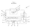
- FIG. 1 schematically shows a conventional air conditioner 1.
- a conventional air conditioner with a dehumidification function includes a compressor unit 10 for compressing coolant, an outdoor heat exchanger unit 20, an indoor heat exchanger unit 30 and an expansion unit 40 disposed between the outdoor heat exchanger unit 20 and the indoor heat exchanger unit 30.
- the outdoor heat exchanger unit 20 has a heat exchanger 21 and a fan 22 to enable heat exchange between coolant and outdoor air.
- the indoor heat exchanger unit 30 has a first heat exchanger 31, a second heat exchanger 32 and indoor expanders 33 and 34 disposed between the first and the second heat exchangers 31 and 32.
- the compressor unit 10 has a compressor 11 for converting low temperature and pressure gas coolant dispensed from the outdoor heat exchanger unit 20 or the indoor heat exchanger unit 30 into high temperature and pressure gas coolant, and a four-way valve 12 for regulating the dispensing direction of the compressor 11.
- the four-way valve 12 switches suction and exhaust ducts of the compressor 11 so that the indoor heat exchanger unit 30 may operate as an evaporator in the event of cooling the indoor or as a condenser in the event of heating the indoor.
- the outdoor heat exchanger unit 20 naturally operates as the condenser or the evaporator correspondingly.
- the outdoor heat exchanger unit 20 serves to convert high temperature and pressure gas coolant generated in the compressor unit 10 into middle temperature and high pressure liquid coolant, and is equipped with the condenser 21 and the fan 22 to this end.
- the expansion unit 40 is means for converting middle temperature-high pressure liquid coolant dispensed from the outdoor heat exchanger unit 20 into low temperature-pressure liquid coolant.
- the expansion unit 40 includes a capillary 41 and a first valve 42 disposed parallel with the capillary 41 for regulating flow of liquid coolant through the capillary 41.
- the air conditioner operates as a dehumidifier, it is necessary to control the pass of the coolant through the capillary 41 such that the expansion cycle in the expansion unit 40 does not occur.
- the first valve 42 is opened such that the liquid coolant passes through the first valve 42, so that the expansion unit 40 will not perform an expansion cycle.
- the expansion cycle is not performed as above, middle temperature-high pressure coolant is introduced into the indoor heat exchanger unit 30. Then, since the indoor heat exchanger unit 30 includes the first heat exchanger 31, the second heat exchanger 32 and the indoor expanders 33 and 34 between the first and second heat exchangers 31 and 32, the first heat exchanger 31 performs a condensing action once more while the indoor expander 33 performs the expansion cycle.
- middle temperature-high pressure liquid coolant is converted into low temperature-pressure liquid coolant, and the converted low temperature-pressure liquid coolant in the second heat exchanger 32 absorbs surrounding heat to be evaporated into low temperature-pressure gas coolant and the evaporated low temperature-pressure gas coolant is then introduced into the compressor unit 10.
- the expansion unit 40 performs the expansion cycle and the first heat exchanger 31 operates as an evaporator like the second heat exchanger 32. At this time, of course, the second valve 34 of the indoor expander 33 is opened to disable the indoor expander 33.
- the second heat exchanger 32 As the temperature drops owing to evaporation of coolant, ambient moisture is condensed. Thus condensed moisture is discharged to the outside to carry out the dehumidification operation.
- the first heat exchanger 31 operates as a condenser to have temperature balance, thereby preventing the indoor temperature from dropping.
- the conventional air conditioner performs the dehumidification operation regardless of the humidity difference between the set humidity and the indoor humidity, and the outdoor load, so that it fails to optimize the operation of the compressor and causes waste of the power to operate the air conditioner.
- the present invention is directed to a power saving dehumidification method of an air conditioner that substantially obviates one or more problems due to limitations and disadvantages of the related art.
- An object of the present invention is to provide a power saving dehumidification method of an air conditioner in which revolution rates of the indoor fan and the outdoor fan are adjusted and the frequency of the compressor is determined according to a humidity difference between a set humidity and an indoor humidity to optimize the operation of the compressor according to an outdoor load in the air conditioner and remarkably save the power required for driving the air conditioner.
- a power saving dehumidification method of an air conditioner comprises the steps of: (a) detecting an indoor humidity by an indoor humidity sensor installed in the air conditioner and comparing the detected indoor humidity with a set humidity (which is set by a controller including a remote controller) to obtain a humidity difference between the detected indoor humidity and the set humidity; (b) setting a revolution rate of an indoor fan according to the humidity difference between the detected indoor humidity and the set humidity obtained in the step (a); (c) setting a frequency of a compressor by a compressor-operating algorithm according to the humidity difference between the detected indoor humidity and the set humidity obtained in the step (a); (d) setting a revolution rate of an outdoor fan by an outdoor pan-operating algorithm according to the humidity difference between the detected indoor humidity and the frequency of the compressor obtained in the step (c) and the indoor humidity; and (e) operating the indoor and outdoor fans and the compressor according to the
- the method further comprises the feedback control step of: judging whether the indoor humidity is in a comfortable range and the indoor temperature is maintained to be uniform and if the indoor humidity is not in a comfortable range or the indoor temperature is changed, repeating the steps (a) to (e) until the indoor humidity is in the comfortable range and the indoor temperature is maintained to be uniform.
- the step (b) comprises the steps of: (b-1) if the humidity difference between the indoor humidity and the set humidity is less than or equal to 10 % of the set humidity, setting the revolution rate of the indoor fan to be weak wind; and (b-2) if the humidity difference between the indoor humidity and the set humidity is greater than 10 % of the set humidity, setting the revolution rate of the indoor fan to be strong wind.
- FIG. 1 is a schematic view of the conventional air conditioner
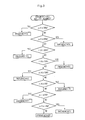
- FIG. 2 is a flowchart illustrating a power saving dehumidification method of an air conditioner according to the present invention
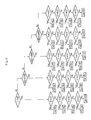
- FIG. 3 is a flowchart illustrating that the frequency of the compressor is set through dehumidification determination in a power saving dehumidification method of an air conditioner according to the present invention.
- FIG. 4 is a flowchart illustrates that the frequency of the compressor is set through constant temperature maintaining determination in a power saving dehumidification method of an air conditioner according to the present invention.
- FIG. 2 is a flowchart illustrating a power saving dehumidification method of an air conditioner according to the present invention.
- a power saving dehumidification method of an air conditioner comprises the steps of: (a) detecting an indoor humidity by an indoor humidity sensor installed in the air conditioner and comparing the detected indoor humidity with a set humidity (which is set by a controller including a remote controller) to obtain a humidity difference between the detected indoor humidity and the set humidity; (b) setting a revolution rate of an indoor fan according to the humidity difference between the detected indoor humidity and the set humidity obtained in the step (a); (c) setting a frequency of a compressor by a compressor-operating algorithm according to the humidity difference between the detected indoor humidity and the set humidity obtained in the step (a); (d) setting a revolution rate of an outdoor fan by an outdoor pan-operating algorithm according to the humidity difference between the detected indoor humidity and the frequency of the compressor obtained in the step (c) and the indoor humidity; and (e) operating the indoor and outdoor fans and the compressor according to the revolution rates of the indoor and outdoor fans and the frequency of the compressor set in the steps (b) to (d), whereby indoor dehumidification operation is continuously performed and uniform
- the method further comprises the feedback control step of: judging whether the indoor humidity is in a comfortable range and the indoor temperature is maintained to be uniform and if the indoor humidity is not in a comfortable range or the indoor temperature is changed, repeating the steps (a) to (e) until the indoor humidity is in the comfortable range and the indoor temperature is maintained to be uniform.
- the step (b) comprises the steps of: (b-1) if the humidity difference between the indoor humidity and the set humidity is less than or equal to 10 % of the set humidity, setting the revolution rate of the indoor fan to be weak wind; and (b-2) if the humidity difference between the indoor humidity and the set humidity is greater than 10 % of the set humidity, setting the revolution rate of the indoor fan to be strong wind.
- the indoor humidity sensor installed in the air conditioner 1 detects an indoor humidity, and the indoor humidity is compared with a set humidity (which is set by a controller including a remote controller) to obtain the humidity difference (S201).
- the revolution rate of the indoor fan is set according to the humidity difference between the indoor humidity and the set humidity. It is judged whether the humidity difference ⁇ H is greater than 10 % (S202). If the humidity difference ⁇ H is greater than 10 % of the set humidity, the revolution rate of the indoor fan is set to be strong wind mode (S203). If the humidity difference between the indoor humidity and the set humidity is less than 10 % of the set humidity, the revolution rate of the indoor fan is set to be weak wind mode (S204).
- a subroutine process for judging dehumidification ability is performed in which the frequency of the compressor 11 is set through a compressor-operating algorithm according to the humidity difference between the obtained indoor humidity and the set humidity (S205).
- the revolution rate of the outdoor fan 22 is determined according to a subroutine process for uniform temperature (S206).
- the frequency of the compressor 11 and the revolution rates of the indoor fan 35 and the outdoor fan 22 are set through the steps S202 to S206, and the compressor 11, the indoor fan 35 and the outdoor fan 22 are operated according to the set values so that the indoor dehumidification and uniform indoor temperature are maintained continuously in a comfortable range, thereby allowing users to feel the comfortable indoor environment (S207).
- the indoor fan, the outdoor fan and the compressor are operated so as to satisfy the uniform indoor temperature and indoor dehumidification target, and a feedback system checks whether the uniform indoor temperature and indoor dehumidification target are satisfied. If it is judged that the uniform indoor temperature and indoor dehumidification target are satisfied, the power saving dehumidification method of an air conditioner according to the present invention is ended.
- FIG. 3 is a flowchart illustrating that the frequency of the compressor is set through dehumidification determination in a power saving dehumidification method of an air conditioner according to the present invention.
- the compressor-operating algorithm includes the steps of: a first step of detecting the indoor humidity by the indoor humidity sensor (not shown) installed in the air conditioner 1 and comparing the detected indoor humidity with the set humidity (which is set by a controller such as a remote controller) to obtain the humidity difference between the detected indoor humidity and the set humidity; a second step of comparing the humidity difference obtained in the first step with the set humidity to obtain a fraction of the humidity difference with respect to the set humidity; and a third step of setting the frequency of the compressor 11 corresponding to the fraction of the humidity difference (indoor humidity - set humidity) obtained in the second step.
- H Set humidity - indoor humidity COMP F (Dehumidification Ability) H F H ⁇ 30% F5 25% ⁇ H ⁇ 29% F4 20% ⁇ H ⁇ 24% F3 15% ⁇ H ⁇ 19% F2 10% ⁇ H ⁇ 14% F2 5% ⁇ H ⁇ 9% F1 0% ⁇ H ⁇ 4% F1 -5% ⁇ H ⁇ -1% F1 H ⁇ -6% OFF
- Table 1 illustrates that the frequency of the compressor 11 is controlled variably according to the humidity difference between the indoor humidity and the set humidity (which is set by a controller such as remote controller) by a compressor-operating algorithm, in which ⁇ H is the humidity difference between the indoor humidity and the set humidity, and F is the rotation frequency of the compressor.
- the frequency of the compressor 11 is set to a first compressor frequency F5.
- the frequency of the compressor is set to a second compressor frequency F4 which is lower than the first compressor frequency F5 by one step.
- the frequency of the compressor is set to a third compressor frequency F3 which is lower than the second compressor frequency F4 by one step.
- the frequency of the compressor is set to a fourth compressor frequency F2 which is lower than the third compressor frequency F3 by one step.
- the frequency of the compressor is set to a fifth compressor frequency F1 which is lower than the fourth compressor frequency F2 by one step.
- the frequency of the compressor is set to 0 (OFF).
- FIG. 4 is a flowchart illustrates that the frequency of the compressor is set through constant temperature maintaining determination in a power saving dehumidification method of an air conditioner according to the present invention.
- the outdoor fan-operating algorithm includes (d-1) comparing the frequency of the compressor controlled variably by the compressor-operating algorithm with the indoor humidity detected by the indoor humidity sensor installed in the air conditioner 1; and (d-2) setting the revolution rate of the outdoor fan 22 proportional to the variably controlled frequency of the compressor, whereby the indoor dehumidification operation can be performed in a comfortable condition using the variably controlled frequency of the compressor.
- Table 2 illustrates that the revolution rate of the outdoor fan 22 is controlled variably according to the frequency of the compressor 11 set depending on Table 1 and the indoor humidity through an outdoor fan-operating algorithm.
- F is a rotation frequency of the compressor 11.
- the revolution rate of the outdoor fan is controlled variably according compressor frequency and indoor humidity set by Table 1.
- the revolution rate of the outdoor fan is set to 100%.
- the revolution rate of the outdoor fan is set to 98 %.
- the revolution rate of the outdoor fan is set to 96 %.
- the revolution rate of the outdoor fan is set to 92 %.
- the revolution rate of the outdoor fan is set to 86 %.
- the revolution rate of the outdoor fan is set to 85 %.
- the indoor humidity is greater than or equal to 65% and less than or equal to 74% and the frequency of the compressor set by Table 1 is F2
- setting the revolution rate of the outdoor fan is set to 86 %.
- the indoor humidity is greater than or equal to 65% and less than or equal to 74% and the frequency of the compressor set by Table 1 is F3
- the revolution rate of the outdoor fan is set to 90 %.
- the revolution rate of the outdoor fan is set to 85 %.
- the revolution rate of the outdoor fan is set to 80 %.
- the revolution rate of the outdoor fan is set to 70 %.
- the revolution rate of the outdoor fan is set to 76 %.
- the revolution rate of the outdoor fan is set to 81 %.
- the revolution rate of the outdoor fan is set to 78 %.
- the revolution rate of the outdoor fan is set to 54 %.
- the revolution rate of the outdoor fan is set to 63 %.
- the revolution rate of the outdoor fan is set to 71 %.
- the revolution rate of the outdoor fan is set to 71 %.
- the revolution rate of the outdoor fan is set to 39 %.
- the revolution rate of the outdoor fan is set to 51 %.
- the revolution rate of the outdoor fan is set to 63 %.
- the revolution rate of the outdoor fan is set to 63 %.
- the revolution rate of the outdoor fan is set to 63 %.
- the revolution rate of the outdoor fan is set to 63 %.
- the revolution rate of the outdoor fan is set to 63 %.
- the revolution rate of the outdoor fan is set to 63 %.
- the revolution rate of the outdoor fan is set to 63 %.
- the rotation of velocity of the outdoor fan depends on the humidity difference step.
- the process is controlled as follows:
- the humidity difference between the indoor humidity and the set humidity set in the air conditioner 1 is compared with the set humidity and judged.
- the indoor humidity is detected by the indoor humidity sensor (not shown) installed in the air conditioner and the detected indoor humidity is compared with a set humidity (which is set by a controller such as a remote controller) to obtain a humidity difference between the detected indoor humidity and the set humidity.
- a revolution rate of the indoor fan 35 is set according to the humidity difference between the detected indoor humidity and the set humidity obtained in the previous step.
- a frequency of the compressor corresponding to the humidity difference (indoor humidity - set humidity) is set by a compressor-operating algorithm by comparing the humidity difference with the set humidity set in the air conditioner 1.
- the revolution rate of the outdoor fan 22 corresponding to the humidity difference is set by an outdoor pan-operating algorithm by comparing frequency of the compressor 1 with the indoor humidity.
- the indoor fan 35, the outdoor fan 22 and the compressor 11 set to the aforementioned revolution rate and frequency are operated so that the indoor dehumidification operation is continuously performed and uniform indoor temperature is maintained in such comfortable condition that a user feels a comfortable indoor atmosphere. It is checked whether the indoor humidity is in a comfortable range and the indoor temperature is maintained to be uniform. If the indoor humidity is not in the comfortable range or the indoor temperature is changed, the steps described above are repeated until the indoor humidity is in the comfortable range and the indoor temperature is maintained to be uniform.
- a power saving dehumidification method of an air conditioner 1 optimizes operation of the compressor, the indoor fan and the outdoor fan according to outdoor load in the air conditioner.
- the compressor, the indoor fan and the outdoor fan are operated to perform dehumidification indoor in response to the outdoor load so that power consumed to drive the air conditioner is greatly saved by 20% to 25 % compared with the conventional air conditioner.
Landscapes
- Engineering & Computer Science (AREA)
- Mechanical Engineering (AREA)
- General Engineering & Computer Science (AREA)
- Chemical & Material Sciences (AREA)
- Combustion & Propulsion (AREA)
- Physics & Mathematics (AREA)
- Fluid Mechanics (AREA)
- Fuzzy Systems (AREA)
- Mathematical Physics (AREA)
- Signal Processing (AREA)
- Thermal Sciences (AREA)
- Air Conditioning Control Device (AREA)
Applications Claiming Priority (2)
| Application Number | Priority Date | Filing Date | Title |
|---|---|---|---|
| KR2003006084 | 2003-01-30 | ||
| KR10-2003-0006084A KR100512280B1 (ko) | 2003-01-30 | 2003-01-30 | 냉난방기의 절전 제습 운전방법 |
Publications (2)
| Publication Number | Publication Date |
|---|---|
| EP1443280A1 true EP1443280A1 (de) | 2004-08-04 |
| EP1443280B1 EP1443280B1 (de) | 2007-04-04 |
Family
ID=32653316
Family Applications (1)
| Application Number | Title | Priority Date | Filing Date |
|---|---|---|---|
| EP03292763A Expired - Lifetime EP1443280B1 (de) | 2003-01-30 | 2003-11-04 | Entfeuchtungsverfahren einer Klimaanlage |
Country Status (4)
| Country | Link |
|---|---|
| EP (1) | EP1443280B1 (de) |
| JP (1) | JP4468682B2 (de) |
| KR (1) | KR100512280B1 (de) |
| CN (1) | CN100366984C (de) |
Cited By (6)
| Publication number | Priority date | Publication date | Assignee | Title |
|---|---|---|---|---|
| WO2006110208A2 (en) | 2005-04-08 | 2006-10-19 | Carrier Corporation | Refrigerant system with variable speed compressor and reheat function |
| CN103375418A (zh) * | 2012-04-27 | 2013-10-30 | 上海宝钢工业技术服务有限公司 | 应用再制造技术后风机节能率的测量方法 |
| US20150039137A1 (en) * | 2007-04-30 | 2015-02-05 | Emerson Electric Co. | Two Mode Thermostat With Set-Back Temperature and Humidity Set-Point Feature |
| CN115235063A (zh) * | 2022-04-13 | 2022-10-25 | 青岛海尔空调器有限总公司 | 空调器的控制方法 |
| CN118729507A (zh) * | 2024-07-11 | 2024-10-01 | 南京晓庄学院 | 一种全新风机组的控制方法及系统 |
| WO2025001143A1 (zh) * | 2023-06-30 | 2025-01-02 | 佛山市顺德区美的电子科技有限公司 | 除湿控制方法、存储介质、除湿控制器和除湿设备 |
Families Citing this family (32)
| Publication number | Priority date | Publication date | Assignee | Title |
|---|---|---|---|---|
| KR101502096B1 (ko) * | 2008-07-22 | 2015-03-12 | 삼성전자 주식회사 | 공기 조화기의 제어 방법 |
| KR101689724B1 (ko) * | 2010-06-21 | 2017-01-02 | 엘지전자 주식회사 | 공기조화기 및 그 제어방법 |
| CN102619771B (zh) * | 2012-03-29 | 2015-05-06 | 美的集团股份有限公司 | 一种风扇舒适风的控制方法 |
| KR102234780B1 (ko) * | 2014-02-03 | 2021-04-01 | 삼성전자주식회사 | 제습기 및 그의 제어 방법 |
| CN106461259B (zh) * | 2014-08-06 | 2019-12-17 | 三菱电机株式会社 | 除湿机 |
| WO2016052245A1 (ja) * | 2014-10-03 | 2016-04-07 | 三菱電機株式会社 | 除湿機 |
| CN105222295A (zh) * | 2015-11-06 | 2016-01-06 | 广东美的制冷设备有限公司 | 空调遥控器、空调器、空调器系统、空调器的控制方法 |
| CN105605741B (zh) * | 2016-01-26 | 2019-04-19 | 广东美的制冷设备有限公司 | 空调的除湿控制方法及装置 |
| US10955164B2 (en) | 2016-07-14 | 2021-03-23 | Ademco Inc. | Dehumidification control system |
| CN106247552B (zh) * | 2016-08-12 | 2019-05-31 | 青岛海尔空调器有限总公司 | 一种用于空调的控制方法、装置及空调 |
| CN106839333A (zh) * | 2017-03-06 | 2017-06-13 | 海信科龙电器股份有限公司 | 一种空调器及其温湿度调节方法 |
| CN107084490B (zh) * | 2017-04-26 | 2020-02-04 | 青岛海尔空调器有限总公司 | 空调器的控制方法和空调器 |
| CN107178835B (zh) * | 2017-06-12 | 2020-06-05 | 广东美的暖通设备有限公司 | 空调器除湿的控制方法、控制装置和空调器 |
| CN107525244B (zh) * | 2017-08-28 | 2020-02-11 | 广东美的暖通设备有限公司 | 空调器的风速控制方法、空调器及存储介质 |
| PL3677850T3 (pl) * | 2017-09-04 | 2024-03-18 | Haier Group Corporation | Sposób sterowania i urządzenie do samoczyszczenia klimatyzatorów i klimatyzator |
| JP7002918B2 (ja) * | 2017-11-08 | 2022-02-04 | 三菱電機株式会社 | 換気システム、空調システム、換気方法及びプログラム |
| CN107883547A (zh) * | 2017-11-10 | 2018-04-06 | 广东美的制冷设备有限公司 | 控制方法、控制系统、计算机可读存储介质和移动空调 |
| CN107642875A (zh) * | 2017-11-10 | 2018-01-30 | 广东美的制冷设备有限公司 | 控制方法、控制系统、计算机可读存储介质和移动空调 |
| CN107883546A (zh) * | 2017-11-10 | 2018-04-06 | 广东美的制冷设备有限公司 | 控制方法、控制系统、计算机可读存储介质和移动空调 |
| CN107676942A (zh) * | 2017-11-10 | 2018-02-09 | 广东美的制冷设备有限公司 | 控制方法、控制系统、计算机可读存储介质和移动空调 |
| US11287172B2 (en) * | 2018-01-29 | 2022-03-29 | Tippmann Companies Llc | Freezer dehumidification system |
| CN111397146B (zh) * | 2020-04-17 | 2022-03-01 | 宁波奥克斯电气股份有限公司 | 空调湿度控制方法、装置、空调器及计算机可读存储介质 |
| CN112128944B (zh) * | 2020-09-07 | 2022-06-28 | 青岛海尔空调器有限总公司 | 用于空调湿度控制的方法、装置及空调 |
| WO2022145694A1 (ko) * | 2020-12-29 | 2022-07-07 | 삼성전자주식회사 | 공기 조화기 및 공기 조화기 제어방법 |
| CN112842218B (zh) * | 2021-01-20 | 2022-09-30 | 宁波方太厨具有限公司 | 一种清洗机烘干方法及应用该方法的清洗机 |
| CN216132007U (zh) * | 2021-03-22 | 2022-03-25 | 青岛海尔空调电子有限公司 | 用于调湿的装置 |
| CN114110974B (zh) * | 2021-11-10 | 2023-03-31 | 珠海格力电器股份有限公司 | 一种空调器的控制方法及空调器 |
| CN114017893B (zh) * | 2021-11-26 | 2023-03-28 | 宁波奥克斯电气股份有限公司 | 一种空调器除湿控制方法及装置和空调器 |
| CN114811831A (zh) * | 2022-04-19 | 2022-07-29 | 青岛海尔空调器有限总公司 | 空调恒温除湿的控制方法、控制系统、电子设备和介质 |
| CN115076971A (zh) * | 2022-05-06 | 2022-09-20 | 重庆海尔空调器有限公司 | 空调器的控制方法、控制装置及空调器 |
| CN115307262B (zh) * | 2022-07-04 | 2024-06-14 | 珠海格力电器股份有限公司 | 一种空调恒温除湿方法、装置及空调系统 |
| CN116358110B (zh) * | 2023-03-29 | 2025-09-16 | 青岛海尔空调器有限总公司 | 空调器的节能控制方法、控制装置、空调器及电子设备 |
Citations (9)
| Publication number | Priority date | Publication date | Assignee | Title |
|---|---|---|---|---|
| JPS5792635A (en) * | 1980-11-29 | 1982-06-09 | Toshiba Corp | Method of controlling air conditioner |
| JPS5927145A (ja) * | 1982-08-03 | 1984-02-13 | Toshiba Corp | 空気調和機 |
| JPS60169039A (ja) * | 1984-02-13 | 1985-09-02 | Mitsubishi Heavy Ind Ltd | 空気調和機の除湿運転制御装置 |
| US4744223A (en) * | 1985-11-29 | 1988-05-17 | Kabushiki Kaisha Toshiba | Air conditioning apparatus |
| US4813474A (en) * | 1986-12-26 | 1989-03-21 | Kabushiki Kaisha Toshiba | Air conditioner apparatus with improved dehumidification control |
| US5062276A (en) * | 1990-09-20 | 1991-11-05 | Electric Power Research Institute, Inc. | Humidity control for variable speed air conditioner |
| US5345776A (en) * | 1992-10-13 | 1994-09-13 | Kabushiki Kaisha Toshiba | Air conditioning apparatus capable of performing a dehumidifying operation |
| US5353862A (en) * | 1992-08-26 | 1994-10-11 | Kabushiki Kaisha Toshiba | Humidity control device of air conditioner |
| EP0893657A1 (de) * | 1997-06-23 | 1999-01-27 | Carrier Corporation | Thermostat und Verfahren zur Feuchtigkeitsregelung für eine Klimaanlage |
Family Cites Families (8)
| Publication number | Priority date | Publication date | Assignee | Title |
|---|---|---|---|---|
| JP3110570B2 (ja) * | 1992-10-26 | 2000-11-20 | 東芝キヤリア株式会社 | 空気調和装置 |
| JPH06241534A (ja) * | 1993-02-12 | 1994-08-30 | Mitsubishi Heavy Ind Ltd | 空気調和機 |
| JP3242729B2 (ja) * | 1993-02-18 | 2001-12-25 | 東芝キヤリア株式会社 | 空気調和装置の制御装置 |
| JPH09280629A (ja) * | 1996-04-10 | 1997-10-31 | Hitachi Ltd | 空気調和機の制御方法およびその装置 |
| JPH11304285A (ja) * | 1998-04-17 | 1999-11-05 | Hitachi Ltd | 空気調和機 |
| JP2001201207A (ja) * | 2000-01-18 | 2001-07-27 | Mitsubishi Heavy Ind Ltd | 空気調和装置 |
| JP2002089933A (ja) * | 2000-09-18 | 2002-03-27 | Matsushita Electric Ind Co Ltd | 空気調和機の制御装置 |
| JP3633560B2 (ja) * | 2002-01-23 | 2005-03-30 | タイガー魔法瓶株式会社 | 除湿機 |
-
2003
- 2003-01-30 KR KR10-2003-0006084A patent/KR100512280B1/ko not_active Expired - Fee Related
- 2003-11-04 EP EP03292763A patent/EP1443280B1/de not_active Expired - Lifetime
- 2003-12-01 CN CNB200310118872XA patent/CN100366984C/zh not_active Expired - Fee Related
- 2003-12-04 JP JP2003405720A patent/JP4468682B2/ja not_active Expired - Fee Related
Patent Citations (9)
| Publication number | Priority date | Publication date | Assignee | Title |
|---|---|---|---|---|
| JPS5792635A (en) * | 1980-11-29 | 1982-06-09 | Toshiba Corp | Method of controlling air conditioner |
| JPS5927145A (ja) * | 1982-08-03 | 1984-02-13 | Toshiba Corp | 空気調和機 |
| JPS60169039A (ja) * | 1984-02-13 | 1985-09-02 | Mitsubishi Heavy Ind Ltd | 空気調和機の除湿運転制御装置 |
| US4744223A (en) * | 1985-11-29 | 1988-05-17 | Kabushiki Kaisha Toshiba | Air conditioning apparatus |
| US4813474A (en) * | 1986-12-26 | 1989-03-21 | Kabushiki Kaisha Toshiba | Air conditioner apparatus with improved dehumidification control |
| US5062276A (en) * | 1990-09-20 | 1991-11-05 | Electric Power Research Institute, Inc. | Humidity control for variable speed air conditioner |
| US5353862A (en) * | 1992-08-26 | 1994-10-11 | Kabushiki Kaisha Toshiba | Humidity control device of air conditioner |
| US5345776A (en) * | 1992-10-13 | 1994-09-13 | Kabushiki Kaisha Toshiba | Air conditioning apparatus capable of performing a dehumidifying operation |
| EP0893657A1 (de) * | 1997-06-23 | 1999-01-27 | Carrier Corporation | Thermostat und Verfahren zur Feuchtigkeitsregelung für eine Klimaanlage |
Non-Patent Citations (3)
| Title |
|---|
| PATENT ABSTRACTS OF JAPAN vol. 006, no. 184 (M - 157) 21 September 1982 (1982-09-21) * |
| PATENT ABSTRACTS OF JAPAN vol. 008, no. 124 (M - 301) 9 June 1984 (1984-06-09) * |
| PATENT ABSTRACTS OF JAPAN vol. 010, no. 006 (M - 445) 11 January 1986 (1986-01-11) * |
Cited By (8)
| Publication number | Priority date | Publication date | Assignee | Title |
|---|---|---|---|---|
| WO2006110208A2 (en) | 2005-04-08 | 2006-10-19 | Carrier Corporation | Refrigerant system with variable speed compressor and reheat function |
| EP1866578A4 (de) * | 2005-04-08 | 2011-10-19 | Carrier Corp | Kühlsystem mit kompressor mit variabler drehzahl und aufwärmfunktion |
| US20150039137A1 (en) * | 2007-04-30 | 2015-02-05 | Emerson Electric Co. | Two Mode Thermostat With Set-Back Temperature and Humidity Set-Point Feature |
| US10001291B2 (en) * | 2007-04-30 | 2018-06-19 | Emerson Electric Co. | Two mode thermostat with set-back temperature and humidity set-point feature |
| CN103375418A (zh) * | 2012-04-27 | 2013-10-30 | 上海宝钢工业技术服务有限公司 | 应用再制造技术后风机节能率的测量方法 |
| CN115235063A (zh) * | 2022-04-13 | 2022-10-25 | 青岛海尔空调器有限总公司 | 空调器的控制方法 |
| WO2025001143A1 (zh) * | 2023-06-30 | 2025-01-02 | 佛山市顺德区美的电子科技有限公司 | 除湿控制方法、存储介质、除湿控制器和除湿设备 |
| CN118729507A (zh) * | 2024-07-11 | 2024-10-01 | 南京晓庄学院 | 一种全新风机组的控制方法及系统 |
Also Published As
| Publication number | Publication date |
|---|---|
| JP4468682B2 (ja) | 2010-05-26 |
| CN1519515A (zh) | 2004-08-11 |
| CN100366984C (zh) | 2008-02-06 |
| KR20040069613A (ko) | 2004-08-06 |
| EP1443280B1 (de) | 2007-04-04 |
| KR100512280B1 (ko) | 2005-09-02 |
| JP2004233034A (ja) | 2004-08-19 |
Similar Documents
| Publication | Publication Date | Title |
|---|---|---|
| EP1443280B1 (de) | Entfeuchtungsverfahren einer Klimaanlage | |
| EP1443278A1 (de) | Entfeuchtungsverfahren einer Klimaanlage | |
| EP1443279B1 (de) | Entfeuchtungsverfahren einer Klimaanlage | |
| EP1398576B1 (de) | Verfahren zum Betrieb einer Klimaanlage und System unter Verwendung desselben | |
| US7240502B2 (en) | Method for controlling operation of air-conditioner | |
| CN113757936B (zh) | 空调控制系统、空调器及空调器的控制方法 | |
| JP4849095B2 (ja) | 空気調和装置 | |
| KR20020075393A (ko) | 공기 조화 장치 | |
| JP2010133589A (ja) | 空気調和機 | |
| JP3835453B2 (ja) | 空気調和装置 | |
| US5209081A (en) | Air conditioner for vehicle | |
| CN111928432B (zh) | 空调器的控制方法 | |
| JPH1096545A (ja) | 空気調和機およびその制御方法 | |
| KR100408468B1 (ko) | 공기 조화용 열 펌프 장치 | |
| JP4074422B2 (ja) | 空調機とその制御方法 | |
| JP2018136074A (ja) | 空気調和システム | |
| JP4288979B2 (ja) | 空気調和装置、及び空気調和装置の運転制御方法 | |
| JPH09318140A (ja) | 空気調和装置 | |
| JP2019163907A (ja) | 空気調和装置及び空気調和システム | |
| JP2008082637A (ja) | 超臨界冷凍サイクル | |
| KR100197684B1 (ko) | 공기조화기의 냉매제어회로 | |
| CN212457128U (zh) | 空气调节系统及空调器 | |
| KR20040033802A (ko) | 제습용 에어컨 제어 방법 | |
| JP2002277019A (ja) | 空気調和装置 | |
| CN118129234A (zh) | 新风除湿机控制方法、装置、存储介质及新风除湿机 |
Legal Events
| Date | Code | Title | Description |
|---|---|---|---|
| PUAI | Public reference made under article 153(3) epc to a published international application that has entered the european phase |
Free format text: ORIGINAL CODE: 0009012 |
|
| AK | Designated contracting states |
Kind code of ref document: A1 Designated state(s): AT BE BG CH CY CZ DE DK EE ES FI FR GB GR HU IE IT LI LU MC NL PT RO SE SI SK TR |
|
| AX | Request for extension of the european patent |
Extension state: AL LT LV MK |
|
| 17P | Request for examination filed |
Effective date: 20050126 |
|
| AKX | Designation fees paid |
Designated state(s): FR GB IT |
|
| REG | Reference to a national code |
Ref country code: DE Ref legal event code: 8566 |
|
| RBV | Designated contracting states (corrected) |
Designated state(s): FR GB IT |
|
| GRAP | Despatch of communication of intention to grant a patent |
Free format text: ORIGINAL CODE: EPIDOSNIGR1 |
|
| GRAS | Grant fee paid |
Free format text: ORIGINAL CODE: EPIDOSNIGR3 |
|
| GRAA | (expected) grant |
Free format text: ORIGINAL CODE: 0009210 |
|
| RAP1 | Party data changed (applicant data changed or rights of an application transferred) |
Owner name: LG ELECTRONICS INC. |
|
| AK | Designated contracting states |
Kind code of ref document: B1 Designated state(s): FR GB IT |
|
| REG | Reference to a national code |
Ref country code: GB Ref legal event code: FG4D |
|
| ET | Fr: translation filed | ||
| PLBE | No opposition filed within time limit |
Free format text: ORIGINAL CODE: 0009261 |
|
| STAA | Information on the status of an ep patent application or granted ep patent |
Free format text: STATUS: NO OPPOSITION FILED WITHIN TIME LIMIT |
|
| 26N | No opposition filed |
Effective date: 20080107 |
|
| REG | Reference to a national code |
Ref country code: FR Ref legal event code: PLFP Year of fee payment: 13 |
|
| REG | Reference to a national code |
Ref country code: FR Ref legal event code: PLFP Year of fee payment: 14 |
|
| PGFP | Annual fee paid to national office [announced via postgrant information from national office to epo] |
Ref country code: FR Payment date: 20161011 Year of fee payment: 14 Ref country code: GB Payment date: 20161006 Year of fee payment: 14 |
|
| PGFP | Annual fee paid to national office [announced via postgrant information from national office to epo] |
Ref country code: IT Payment date: 20161116 Year of fee payment: 14 |
|
| GBPC | Gb: european patent ceased through non-payment of renewal fee |
Effective date: 20171104 |
|
| REG | Reference to a national code |
Ref country code: FR Ref legal event code: ST Effective date: 20180731 |
|
| PG25 | Lapsed in a contracting state [announced via postgrant information from national office to epo] |
Ref country code: FR Free format text: LAPSE BECAUSE OF NON-PAYMENT OF DUE FEES Effective date: 20171130 Ref country code: IT Free format text: LAPSE BECAUSE OF NON-PAYMENT OF DUE FEES Effective date: 20171104 |
|
| PG25 | Lapsed in a contracting state [announced via postgrant information from national office to epo] |
Ref country code: GB Free format text: LAPSE BECAUSE OF NON-PAYMENT OF DUE FEES Effective date: 20171104 |