EP1440835A1 - Angetriebenes Zusatzelement an einem Kraftfahrzeug - Google Patents
Angetriebenes Zusatzelement an einem Kraftfahrzeug Download PDFInfo
- Publication number
- EP1440835A1 EP1440835A1 EP03001461A EP03001461A EP1440835A1 EP 1440835 A1 EP1440835 A1 EP 1440835A1 EP 03001461 A EP03001461 A EP 03001461A EP 03001461 A EP03001461 A EP 03001461A EP 1440835 A1 EP1440835 A1 EP 1440835A1
- Authority
- EP
- European Patent Office
- Prior art keywords
- additional element
- element according
- drive shaft
- gear
- shaft
- Prior art date
- Legal status (The legal status is an assumption and is not a legal conclusion. Google has not performed a legal analysis and makes no representation as to the accuracy of the status listed.)
- Granted
Links
Images
Classifications
-
- B—PERFORMING OPERATIONS; TRANSPORTING
- B60—VEHICLES IN GENERAL
- B60K—ARRANGEMENT OR MOUNTING OF PROPULSION UNITS OR OF TRANSMISSIONS IN VEHICLES; ARRANGEMENT OR MOUNTING OF PLURAL DIVERSE PRIME-MOVERS IN VEHICLES; AUXILIARY DRIVES FOR VEHICLES; INSTRUMENTATION OR DASHBOARDS FOR VEHICLES; ARRANGEMENTS IN CONNECTION WITH COOLING, AIR INTAKE, GAS EXHAUST OR FUEL SUPPLY OF PROPULSION UNITS IN VEHICLES
- B60K25/00—Auxiliary drives
- B60K25/06—Auxiliary drives from the transmission power take-off
Definitions
- the invention relates to an additional element for a Motor vehicle, especially trucks, with the Features of the preamble of claim 1.
- Trucks must be in addition to those for motor vehicles generally common devices still with Supply units such as compressors, pumps, Hydraulic pumps or generators can be equipped. Such devices are for example for loading and unloading the truck necessary and become preferably mechanically by the engine of the truck driven. Otherwise it would be another engine required. Such an additional engine would have increased costs and would be through Dead weight reduce the maximum loadable weight. Therefore, such a solution is not economical meaningful.
- Chassis between the front and rear axles are due to the short wheelbase as well the central drive shaft for the rear axle here too, comparatively little space. This is especially because of this area in addition to the additional elements, the largest possible Fuel tank and a lubricant tank attached Need to become.
- the additional elements are usually driven in the way that the additional element is a cardan shaft has that with an output flange of the transmission connected is.
- a cardan shaft is among others therefore required on the one hand the additional element vibrationally from the rest of the vehicle too decouple and on the other hand a comparatively simple To enable assembly or disassembly of the additional element.
- the invention therefore has the technical problem based on an additional element according to the preamble of Provide claim 1 that saves as much space as possible and at a short distance from the gearbox a propeller shaft can be connected to it and mechanically driven by the engine of the motor vehicle becomes.
- the additional element can also be easily adapted to the structural conditions of different vehicle types. Designing the traction mechanism transmission as a belt transmission with a first belt pulley and a second belt pulley connected to the drive shaft initially leads to a simple and therefore inexpensive solution. In addition, the additional element can be easily adapted to different vehicle types by changing the length of the V-belt or toothed belt.
- the traction mechanism can also be used as a Chain gear should be designed.
- the arranged in the additional element Supply units can be a compressor, a pump, especially hydraulic pump and a generator.
- a fan wheel is provided that is driven with. This cools the gearbox to prevent the temperature of the gear oil exceeds a critical value and that Angular gearbox is damaged.
- housing to provide the angular gear with cooling fins.
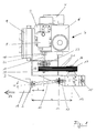
- Fig. 1 is a transmission 1 schematically one Truck shown with an output flange 2, the is provided on the end of an output shaft 3.
- the output shaft 3 provided with the output flange 2 runs in a direction parallel to the direction of travel of the Truck.
- Supply unit can also be a pump, a Act hydraulic pump or a generator.
- the Compressor 5 is together with an air filter 6 Intake damper 7, a pressure silencer 8 and one Air-air cooler 9 on a compressor console 10 arranged.
- the additional element 4 has an articulated shaft 11 and Angular gear 12 on.
- One end of the propeller shaft 11 is connected to the output flange 2 of the transmission 1 and the other end of the propeller shaft 11 is with the Input member 13 of the bevel gear 12 via a Flange 14 connected, the propeller shaft 11 with both the output shaft 3 as well as with the input member 13 of the Angular gear 12 includes a diffraction angle ⁇ .
- the diffraction angle ⁇ is chosen so that it is 15 ° and in particular does not exceed 10 °.
- the diffraction angle ⁇ is chosen so that it is 15 ° and in particular does not exceed 10 °.
- a fan wheel 15 is provided, the is connected to the input member 13 such that it rotates with a rotation of the input member 13 and ensures that the bevel gear 12 is cooled.
- the angular gear 12 has an output member 16 on, which points in the direction of the compressor 5 and thus perpendicular to the output shaft 3 and the Output flange 2 stands.
- a first pulley 17 is provided on the output member 16 on the output member 16 on the output member 16 .
- the Axis of rotation of the drive shaft 19 is perpendicular to Output shaft 3 and thus also perpendicular to the axis of rotation of the output flange 2.
- the Output flange 2, the output member 16 of the Angular gear 12 and the drive shaft 19 such arranged relative to each other that the distance a of Axis of rotation of the output member 16 from the output flange 2 is greater than the distance b of the axis of rotation Drive shaft 19 from the output flange 2.
- first pulley 17 and the second pulley 20 via three V-belts 21 are interconnected.
- the first and the second Form pulley 17 and 20 and the V-belt 21 thus a traction mechanism through which the output member 16 and the drive shaft 19 are connected to each other.
- the traction mechanism can also be used as Chain gear should be designed, instead of Pulleys 17, 20 sprockets are provided are connected to each other via at least one chain.
- the output member 16 is located from the viewpoint of the transmission 1 seen behind the drive shaft 19. With this arrangement of the angular gear 12 relative to the drive shaft 19 together with the pulley 17, 20 and V-belt 21 formed traction mechanism gear runs the cardan shaft 11 almost completely within by the rest Parts of the additional element 4 occupied space.
- the propeller shaft 11 has a sufficient length by the distance between the output flange 2 and Input member 13 perpendicular to the output shaft 3 bridge without the diffraction angle ⁇ a critical area reached above 10 °.
- the transmission 1 If the transmission 1 is operated such that the Turn output shaft 3 and output flange 2, transmits the propeller shaft 11 to the rotary motion Angular gear 12, the output member 15 also in Rotation is offset. About the traction mechanism formed from the pulleys 17, 20 and the V-belts 21, the rotational movement on the drive shaft 19 transferred and thus the compressor 5 driven.
Landscapes
- Engineering & Computer Science (AREA)
- Chemical & Material Sciences (AREA)
- Combustion & Propulsion (AREA)
- Transportation (AREA)
- Mechanical Engineering (AREA)
- Auxiliary Drives, Propulsion Controls, And Safety Devices (AREA)
- Control Of Electric Motors In General (AREA)
- Control Of Multiple Motors (AREA)
- Power Steering Mechanism (AREA)
- Arrangement Or Mounting Of Propulsion Units For Vehicles (AREA)
Abstract
Description
Das Zugmittelgetriebe als Riemengetriebe mit einer ersten Riemenscheibe und einer zweiten, mit der Antriebswelle verbundenen Riemenscheibe auszubilden, führt zunächst zu einer einfachen und damit kostengünstigen Lösung. Außerdem kann das Zusatzelement durch Längenänderung des Keilriemens oder Zahnriemens leicht an unterschiedliche Fahrzeugtypen angepasst werden.
- Fig. 1
- die Draufsicht auf ein erfindungsgemäßes Zusatzelement.
Claims (15)
- Zusatzelement (4) für ein Kraftfahrzeug, das einen Motor und ein einen Abtriebsflansch (2) aufweisendes Getriebe (1) aufweist,dadurch gekennzeichnet,mit einem versorgungsaggregat (5),mit einer Gelenkwelle (11) undmit einer Antriebswelle(19),wobei die Antriebswelle(19) eine Drehbewegung auf das Versorgungsaggregat (5) überträgt,dass die Drehachse des Abtriebsflansches (2) und die Drehachse der Antriebswelle (19) im Wesentlichen senkrecht zueinander ausgerichtet und beabstandet zueinander angeordnet sind,dass ein Winkelgetriebe (12) vorgesehen ist,dass die Gelenkwelle (11) das Getriebe (1) mit dem Eingangsglied (13) des Winkelgetriebes (12) verbindet,dass die Antriebswelle (19) und das Ausgangsglied (16) des Winkelgetriebes (12) über ein Zugmittelgetriebe (17, 20, 21) miteinander verbunden sind,dass das Winkelgetriebe (12) und das Zugmittelgetriebe (17, 20, 21) die Drehbewegung der Gelenkwelle (11) auf die Antriebswelle (19) übertragen unddass der Abstand (a) der Drehachse des Ausgangsglieds (16) des Winkelgetriebes (12) vom Abtriebsflansch (2) größer als der Abstand (b) der Drehachse der Antriebswelle (19) vom Abtriebsflansch (2) ist.
- Zusatzelement nach Anspruch 1,
dadurch gekennzeichnet, dass das Zugmittelgetriebe (17, 20, 21) als Riemengetriebe ausgebildet ist. - Zusatzelement nach Anspruch 2,
dadurch gekennzeichnet, dass das Riemengetriebe am Ausgangsglied (16) des Winkelgetriebes (12) eine erste Riemenscheibe (17) und auf der Antriebswelle (19) eine zweite Riemenscheibe (20) aufweist. - Zusatzelement nach Anspruch 3,
dadurch gekennzeichnet, dass die erste und die zweite Riemenscheibe (17, 20) mit mindestens einem Keilriemen (21) miteinander verbunden sind. - Zusatzelement nach Anspruch 3,
dadurch gekennzeichnet, dass die erste und die zweite Riemenscheibe (17, 20) mit mindestens einem Zahnriemen miteinander verbunden sind. - Zusatzelement nach Anspruch 1,
dadurch gekennzeichnet, dass das Zugmittelgetriebe als Kettengetriebe ausgebildet ist. - Zusatzelement nach Anspruch 6,
dadurch gekennzeichnet, dass das Kettengetriebe am Ausgangsglied (16) des Winkelgetriebes (12) ein erstes Kettenrad und auf der Antriebswelle (19) ein zweites Kettenrad aufweist. - Zusatzelement nach Anspruch 7,
dadurch gekennzeichnet, dass das erste und das zweite Kettenrad mit mindestens einer Kette miteinander verbunden sind. - Zusatzelement nach einem der Ansprüche 1 bis 8,
dadurch gekennzeichnet, dass das Versorgungsaggregat als Kompressor (5) ausgebildet ist. - Zusatzelement nach einem der Ansprüche 1 bis 8,
dadurch gekennzeichnet, dass das Versorgungsaggregat als Pumpe, insbesondere Hydraulikpumpe, ausgebildet ist. - Zusatzelement nach einem der Ansprüche 1 bis 8,
dadurch gekennzeichnet, dass das Versorgungsaggregat als Generator ausgebildet ist. - Zusatzelement nach einem der Ansprüche 1 bis 11,
dadurch gekennzeichnet, dass das Winkelgetriebe (12) an der dem Eingangsglied (13) gegenüberliegenden Seite ein Lüfterrad (15) aufweist. - Zusatzelement nach einem der Ansprüche 1 bis 12,
dadurch gekennzeichnet, dass das Winkelgetriebe (12) Kühlrippen aufweist. - Zusatzelement nach einem der Ansprüche 1 bis 13,
dadurch gekennzeichnet, dass der Beugungswinkel α der Gelenkwelle (11) kleiner als 15° ist, vorzugsweise kleiner 10° ist. - Zusatzelement nach einem der Ansprüche 1 bis 14,
dadurch gekennzeichnet, dass ein Lager (23) für die Antriebswelle (19) nahe dem Zugmittelgetriebe vorgesehen ist.
Priority Applications (5)
| Application Number | Priority Date | Filing Date | Title |
|---|---|---|---|
| DE50301607T DE50301607D1 (de) | 2003-01-22 | 2003-01-22 | Angetriebenes Zusatzelement an einem Kraftfahrzeug |
| AT03001461T ATE309108T1 (de) | 2003-01-22 | 2003-01-22 | Angetriebenes zusatzelement an einem kraftfahrzeug |
| EP03001461A EP1440835B1 (de) | 2003-01-22 | 2003-01-22 | Angetriebenes Zusatzelement an einem Kraftfahrzeug |
| ES03001461T ES2256599T3 (es) | 2003-01-22 | 2003-01-22 | Elemento adicional accionado para un automovil. |
| GB0305193A GB2389087B (en) | 2003-01-22 | 2003-03-06 | Powered auxiliary element on a motor vehicle |
Applications Claiming Priority (1)
| Application Number | Priority Date | Filing Date | Title |
|---|---|---|---|
| EP03001461A EP1440835B1 (de) | 2003-01-22 | 2003-01-22 | Angetriebenes Zusatzelement an einem Kraftfahrzeug |
Publications (2)
| Publication Number | Publication Date |
|---|---|
| EP1440835A1 true EP1440835A1 (de) | 2004-07-28 |
| EP1440835B1 EP1440835B1 (de) | 2005-11-09 |
Family
ID=8185865
Family Applications (1)
| Application Number | Title | Priority Date | Filing Date |
|---|---|---|---|
| EP03001461A Expired - Lifetime EP1440835B1 (de) | 2003-01-22 | 2003-01-22 | Angetriebenes Zusatzelement an einem Kraftfahrzeug |
Country Status (5)
| Country | Link |
|---|---|
| EP (1) | EP1440835B1 (de) |
| AT (1) | ATE309108T1 (de) |
| DE (1) | DE50301607D1 (de) |
| ES (1) | ES2256599T3 (de) |
| GB (1) | GB2389087B (de) |
Families Citing this family (2)
| Publication number | Priority date | Publication date | Assignee | Title |
|---|---|---|---|---|
| ITUB20159734A1 (it) | 2015-12-22 | 2017-06-22 | Pierangelo Vercellino | Veicolo con rimorchio, collegato operativamente a esso mediante un cardano |
| RU2688106C1 (ru) * | 2017-06-20 | 2019-05-17 | Дамир Мугаллимович Хабибуллин | Отбор мощности от раздаточной коробки |
Citations (3)
| Publication number | Priority date | Publication date | Assignee | Title |
|---|---|---|---|---|
| US2766628A (en) * | 1954-11-15 | 1956-10-16 | Wilson John Hart | Power take-off for trucks |
| US5563541A (en) | 1994-05-19 | 1996-10-08 | Sony/Tektronix Corporation | Load current detection circuit |
| DE20214999U1 (de) * | 2002-03-22 | 2002-12-19 | Schuebler Fahrzeugtechnik Gmbh | Angetriebenes Zusatzelement an einem Kraftfahrzeug |
Family Cites Families (1)
| Publication number | Priority date | Publication date | Assignee | Title |
|---|---|---|---|---|
| CA2146394A1 (en) * | 1995-04-05 | 1996-10-06 | Kazutoshi Furukawa | Power supply apparatus installed under a carrier of a vehicle |
-
2003
- 2003-01-22 DE DE50301607T patent/DE50301607D1/de not_active Expired - Lifetime
- 2003-01-22 AT AT03001461T patent/ATE309108T1/de not_active IP Right Cessation
- 2003-01-22 EP EP03001461A patent/EP1440835B1/de not_active Expired - Lifetime
- 2003-01-22 ES ES03001461T patent/ES2256599T3/es not_active Expired - Lifetime
- 2003-03-06 GB GB0305193A patent/GB2389087B/en not_active Expired - Fee Related
Patent Citations (3)
| Publication number | Priority date | Publication date | Assignee | Title |
|---|---|---|---|---|
| US2766628A (en) * | 1954-11-15 | 1956-10-16 | Wilson John Hart | Power take-off for trucks |
| US5563541A (en) | 1994-05-19 | 1996-10-08 | Sony/Tektronix Corporation | Load current detection circuit |
| DE20214999U1 (de) * | 2002-03-22 | 2002-12-19 | Schuebler Fahrzeugtechnik Gmbh | Angetriebenes Zusatzelement an einem Kraftfahrzeug |
Also Published As
| Publication number | Publication date |
|---|---|
| DE50301607D1 (de) | 2005-12-15 |
| GB2389087B (en) | 2004-06-02 |
| GB0305193D0 (en) | 2003-04-09 |
| ATE309108T1 (de) | 2005-11-15 |
| GB2389087A (en) | 2003-12-03 |
| EP1440835B1 (de) | 2005-11-09 |
| ES2256599T3 (es) | 2006-07-16 |
Similar Documents
| Publication | Publication Date | Title |
|---|---|---|
| DE60104318T2 (de) | Antriebsstrang | |
| DE1963019A1 (de) | Antrieb fuer Kraftfahrzeuge | |
| DE102005017754A1 (de) | Baumaschine insbesondere Strassenfräsmaschine, Recycler oder Stabilisierer, sowie Antriebsstrang für derartige Baumaschinen | |
| DE1967064U (de) | Antriebsanordnung fuer kraftfahrzeuge. | |
| DE4027901A1 (de) | Allradangetriebenes motorfahrzeug vom typ mit querliegendem motor | |
| EP3647097A1 (de) | Motorfahrzeugantrieb | |
| DE4207193A1 (de) | Montagestruktur fuer eine fahrzeug-kraftuebertragungseinheit | |
| DE2106366A1 (de) | Durch einen Motor mit rotierendem Kolben angetriebenes Kraftfahrzeug | |
| DE60223643T2 (de) | Horizontales Getriebe- und Schmierölsystem für Teleskopkräne | |
| DE102018204910A1 (de) | Nebenabtriebsanordnung | |
| DE2948195A1 (de) | Getriebe als hauptantrieb fuer ein von einer verbrennungskraftmaschine angetriebenes fahrzeug | |
| DE4143102A1 (de) | Kraftuebertragungsteil fuer ein kraftfahrzeug | |
| EP1346867B1 (de) | Angetriebene Zusatzeinrichtung an einem Kraftfahrzeug | |
| EP1440835B1 (de) | Angetriebenes Zusatzelement an einem Kraftfahrzeug | |
| EP3115242B1 (de) | Lüfterantrieb für ein kraftfahrzeug | |
| DE2659282A1 (de) | Kraftfahrzeug mit einer brennkraftmaschine | |
| DE2803840A1 (de) | Triebwerk fuer ein kraftfahrzeug | |
| EP3831635A1 (de) | Antriebsstrang für eine landwirtschaftliche arbeitsmaschine | |
| DE19841590A1 (de) | Anordnung und antriebsmäßige Anbindung von Nebenaggregaten an einer Brennkraftmaschine | |
| DE102011118111A1 (de) | Antriebsstrang für einen Kraftwagen | |
| DE69919958T2 (de) | Traktor mit Schmierungssystem | |
| DE102015220888A1 (de) | Nebenabtriebskopf | |
| EP0648638B1 (de) | Antriebskombination | |
| DE4111983B4 (de) | Antriebseinheit für ein Fahrzeug | |
| DE4118266A1 (de) | Allradantrieb |
Legal Events
| Date | Code | Title | Description |
|---|---|---|---|
| PUAI | Public reference made under article 153(3) epc to a published international application that has entered the european phase |
Free format text: ORIGINAL CODE: 0009012 |
|
| AK | Designated contracting states |
Kind code of ref document: A1 Designated state(s): AT BE BG CH CY CZ DE DK EE ES FI FR GB GR HU IE IT LI LU MC NL PT SE SI SK TR |
|
| AX | Request for extension of the european patent |
Extension state: AL LT LV MK RO |
|
| RAP1 | Party data changed (applicant data changed or rights of an application transferred) |
Owner name: PONTE VECCHIO CONSULT SAGL |
|
| 17P | Request for examination filed |
Effective date: 20041004 |
|
| 17Q | First examination report despatched |
Effective date: 20041208 |
|
| AKX | Designation fees paid |
Designated state(s): AT BE BG CH CY CZ DE DK EE ES FI FR GB GR HU IE IT LI LU MC NL PT SE SI SK TR |
|
| GRAP | Despatch of communication of intention to grant a patent |
Free format text: ORIGINAL CODE: EPIDOSNIGR1 |
|
| GRAS | Grant fee paid |
Free format text: ORIGINAL CODE: EPIDOSNIGR3 |
|
| GRAA | (expected) grant |
Free format text: ORIGINAL CODE: 0009210 |
|
| AK | Designated contracting states |
Kind code of ref document: B1 Designated state(s): AT BE BG CH CY CZ DE DK EE ES FI FR GB GR HU IE IT LI LU MC NL PT SE SI SK TR |
|
| PG25 | Lapsed in a contracting state [announced via postgrant information from national office to epo] |
Ref country code: SI Free format text: LAPSE BECAUSE OF FAILURE TO SUBMIT A TRANSLATION OF THE DESCRIPTION OR TO PAY THE FEE WITHIN THE PRESCRIBED TIME-LIMIT Effective date: 20051109 Ref country code: FI Free format text: LAPSE BECAUSE OF FAILURE TO SUBMIT A TRANSLATION OF THE DESCRIPTION OR TO PAY THE FEE WITHIN THE PRESCRIBED TIME-LIMIT Effective date: 20051109 Ref country code: IE Free format text: LAPSE BECAUSE OF FAILURE TO SUBMIT A TRANSLATION OF THE DESCRIPTION OR TO PAY THE FEE WITHIN THE PRESCRIBED TIME-LIMIT Effective date: 20051109 Ref country code: GB Free format text: LAPSE BECAUSE OF FAILURE TO SUBMIT A TRANSLATION OF THE DESCRIPTION OR TO PAY THE FEE WITHIN THE PRESCRIBED TIME-LIMIT Effective date: 20051109 Ref country code: SK Free format text: LAPSE BECAUSE OF FAILURE TO SUBMIT A TRANSLATION OF THE DESCRIPTION OR TO PAY THE FEE WITHIN THE PRESCRIBED TIME-LIMIT Effective date: 20051109 Ref country code: CZ Free format text: LAPSE BECAUSE OF FAILURE TO SUBMIT A TRANSLATION OF THE DESCRIPTION OR TO PAY THE FEE WITHIN THE PRESCRIBED TIME-LIMIT Effective date: 20051109 Ref country code: IT Free format text: LAPSE BECAUSE OF FAILURE TO SUBMIT A TRANSLATION OF THE DESCRIPTION OR TO PAY THE FEE WITHIN THE PRESCRIBED TIME-LIMIT;WARNING: LAPSES OF ITALIAN PATENTS WITH EFFECTIVE DATE BEFORE 2007 MAY HAVE OCCURRED AT ANY TIME BEFORE 2007. THE CORRECT EFFECTIVE DATE MAY BE DIFFERENT FROM THE ONE RECORDED. Effective date: 20051109 |
|
| REG | Reference to a national code |
Ref country code: GB Ref legal event code: FG4D Free format text: NOT ENGLISH |
|
| REG | Reference to a national code |
Ref country code: CH Ref legal event code: EP |
|
| REG | Reference to a national code |
Ref country code: IE Ref legal event code: FG4D Free format text: LANGUAGE OF EP DOCUMENT: GERMAN |
|
| REF | Corresponds to: |
Ref document number: 50301607 Country of ref document: DE Date of ref document: 20051215 Kind code of ref document: P |
|
| PG25 | Lapsed in a contracting state [announced via postgrant information from national office to epo] |
Ref country code: MC Free format text: LAPSE BECAUSE OF NON-PAYMENT OF DUE FEES Effective date: 20060131 Ref country code: LU Free format text: LAPSE BECAUSE OF NON-PAYMENT OF DUE FEES Effective date: 20060131 |
|
| PG25 | Lapsed in a contracting state [announced via postgrant information from national office to epo] |
Ref country code: SE Free format text: LAPSE BECAUSE OF FAILURE TO SUBMIT A TRANSLATION OF THE DESCRIPTION OR TO PAY THE FEE WITHIN THE PRESCRIBED TIME-LIMIT Effective date: 20060209 Ref country code: GR Free format text: LAPSE BECAUSE OF FAILURE TO SUBMIT A TRANSLATION OF THE DESCRIPTION OR TO PAY THE FEE WITHIN THE PRESCRIBED TIME-LIMIT Effective date: 20060209 Ref country code: DK Free format text: LAPSE BECAUSE OF FAILURE TO SUBMIT A TRANSLATION OF THE DESCRIPTION OR TO PAY THE FEE WITHIN THE PRESCRIBED TIME-LIMIT Effective date: 20060209 Ref country code: BG Free format text: LAPSE BECAUSE OF FAILURE TO SUBMIT A TRANSLATION OF THE DESCRIPTION OR TO PAY THE FEE WITHIN THE PRESCRIBED TIME-LIMIT Effective date: 20060209 |
|
| PG25 | Lapsed in a contracting state [announced via postgrant information from national office to epo] |
Ref country code: PT Free format text: LAPSE BECAUSE OF FAILURE TO SUBMIT A TRANSLATION OF THE DESCRIPTION OR TO PAY THE FEE WITHIN THE PRESCRIBED TIME-LIMIT Effective date: 20060410 |
|
| REG | Reference to a national code |
Ref country code: CH Ref legal event code: NV Representative=s name: TROESCH SCHEIDEGGER WERNER AG |
|
| PG25 | Lapsed in a contracting state [announced via postgrant information from national office to epo] |
Ref country code: HU Free format text: LAPSE BECAUSE OF FAILURE TO SUBMIT A TRANSLATION OF THE DESCRIPTION OR TO PAY THE FEE WITHIN THE PRESCRIBED TIME-LIMIT Effective date: 20060510 |
|
| GBV | Gb: ep patent (uk) treated as always having been void in accordance with gb section 77(7)/1977 [no translation filed] |
Effective date: 20051109 |
|
| REG | Reference to a national code |
Ref country code: IE Ref legal event code: FD4D |
|
| REG | Reference to a national code |
Ref country code: ES Ref legal event code: FG2A Ref document number: 2256599 Country of ref document: ES Kind code of ref document: T3 |
|
| ET | Fr: translation filed | ||
| PLBE | No opposition filed within time limit |
Free format text: ORIGINAL CODE: 0009261 |
|
| STAA | Information on the status of an ep patent application or granted ep patent |
Free format text: STATUS: NO OPPOSITION FILED WITHIN TIME LIMIT |
|
| 26N | No opposition filed |
Effective date: 20060810 |
|
| PGFP | Annual fee paid to national office [announced via postgrant information from national office to epo] |
Ref country code: CH Payment date: 20080129 Year of fee payment: 6 Ref country code: ES Payment date: 20080201 Year of fee payment: 6 |
|
| PGFP | Annual fee paid to national office [announced via postgrant information from national office to epo] |
Ref country code: NL Payment date: 20080130 Year of fee payment: 6 |
|
| PG25 | Lapsed in a contracting state [announced via postgrant information from national office to epo] |
Ref country code: EE Free format text: LAPSE BECAUSE OF FAILURE TO SUBMIT A TRANSLATION OF THE DESCRIPTION OR TO PAY THE FEE WITHIN THE PRESCRIBED TIME-LIMIT Effective date: 20051109 |
|
| PGFP | Annual fee paid to national office [announced via postgrant information from national office to epo] |
Ref country code: AT Payment date: 20080129 Year of fee payment: 6 |
|
| PG25 | Lapsed in a contracting state [announced via postgrant information from national office to epo] |
Ref country code: TR Free format text: LAPSE BECAUSE OF FAILURE TO SUBMIT A TRANSLATION OF THE DESCRIPTION OR TO PAY THE FEE WITHIN THE PRESCRIBED TIME-LIMIT Effective date: 20051109 |
|
| PGFP | Annual fee paid to national office [announced via postgrant information from national office to epo] |
Ref country code: FR Payment date: 20080129 Year of fee payment: 6 |
|
| PGFP | Annual fee paid to national office [announced via postgrant information from national office to epo] |
Ref country code: BE Payment date: 20080304 Year of fee payment: 6 |
|
| PG25 | Lapsed in a contracting state [announced via postgrant information from national office to epo] |
Ref country code: CY Free format text: LAPSE BECAUSE OF FAILURE TO SUBMIT A TRANSLATION OF THE DESCRIPTION OR TO PAY THE FEE WITHIN THE PRESCRIBED TIME-LIMIT Effective date: 20051109 |
|
| REG | Reference to a national code |
Ref country code: CH Ref legal event code: PL |
|
| NLV4 | Nl: lapsed or anulled due to non-payment of the annual fee |
Effective date: 20090801 |
|
| PG25 | Lapsed in a contracting state [announced via postgrant information from national office to epo] |
Ref country code: CH Free format text: LAPSE BECAUSE OF NON-PAYMENT OF DUE FEES Effective date: 20090131 Ref country code: LI Free format text: LAPSE BECAUSE OF NON-PAYMENT OF DUE FEES Effective date: 20090131 Ref country code: AT Free format text: LAPSE BECAUSE OF NON-PAYMENT OF DUE FEES Effective date: 20090122 |
|
| REG | Reference to a national code |
Ref country code: FR Ref legal event code: ST Effective date: 20091030 |
|
| PG25 | Lapsed in a contracting state [announced via postgrant information from national office to epo] |
Ref country code: NL Free format text: LAPSE BECAUSE OF NON-PAYMENT OF DUE FEES Effective date: 20090801 |
|
| PG25 | Lapsed in a contracting state [announced via postgrant information from national office to epo] |
Ref country code: BE Free format text: LAPSE BECAUSE OF NON-PAYMENT OF DUE FEES Effective date: 20090131 |
|
| REG | Reference to a national code |
Ref country code: ES Ref legal event code: FD2A Effective date: 20090123 |
|
| PG25 | Lapsed in a contracting state [announced via postgrant information from national office to epo] |
Ref country code: ES Free format text: LAPSE BECAUSE OF NON-PAYMENT OF DUE FEES Effective date: 20090123 Ref country code: FR Free format text: LAPSE BECAUSE OF NON-PAYMENT OF DUE FEES Effective date: 20090202 |
|
| PGFP | Annual fee paid to national office [announced via postgrant information from national office to epo] |
Ref country code: DE Payment date: 20100122 Year of fee payment: 8 |
|
| REG | Reference to a national code |
Ref country code: DE Ref legal event code: R119 Ref document number: 50301607 Country of ref document: DE Effective date: 20110802 |
|
| PG25 | Lapsed in a contracting state [announced via postgrant information from national office to epo] |
Ref country code: DE Free format text: LAPSE BECAUSE OF NON-PAYMENT OF DUE FEES Effective date: 20110802 |