EP1440835A1 - Auxiliary drive for a vehicle - Google Patents
Auxiliary drive for a vehicle Download PDFInfo
- Publication number
- EP1440835A1 EP1440835A1 EP03001461A EP03001461A EP1440835A1 EP 1440835 A1 EP1440835 A1 EP 1440835A1 EP 03001461 A EP03001461 A EP 03001461A EP 03001461 A EP03001461 A EP 03001461A EP 1440835 A1 EP1440835 A1 EP 1440835A1
- Authority
- EP
- European Patent Office
- Prior art keywords
- additional element
- element according
- drive shaft
- gear
- shaft
- Prior art date
- Legal status (The legal status is an assumption and is not a legal conclusion. Google has not performed a legal analysis and makes no representation as to the accuracy of the status listed.)
- Granted
Links
Images
Classifications
-
- B—PERFORMING OPERATIONS; TRANSPORTING
- B60—VEHICLES IN GENERAL
- B60K—ARRANGEMENT OR MOUNTING OF PROPULSION UNITS OR OF TRANSMISSIONS IN VEHICLES; ARRANGEMENT OR MOUNTING OF PLURAL DIVERSE PRIME-MOVERS IN VEHICLES; AUXILIARY DRIVES FOR VEHICLES; INSTRUMENTATION OR DASHBOARDS FOR VEHICLES; ARRANGEMENTS IN CONNECTION WITH COOLING, AIR INTAKE, GAS EXHAUST OR FUEL SUPPLY OF PROPULSION UNITS IN VEHICLES
- B60K25/00—Auxiliary drives
- B60K25/06—Auxiliary drives from the transmission power take-off
Definitions
- the invention relates to an additional element for a Motor vehicle, especially trucks, with the Features of the preamble of claim 1.
- Trucks must be in addition to those for motor vehicles generally common devices still with Supply units such as compressors, pumps, Hydraulic pumps or generators can be equipped. Such devices are for example for loading and unloading the truck necessary and become preferably mechanically by the engine of the truck driven. Otherwise it would be another engine required. Such an additional engine would have increased costs and would be through Dead weight reduce the maximum loadable weight. Therefore, such a solution is not economical meaningful.
- Chassis between the front and rear axles are due to the short wheelbase as well the central drive shaft for the rear axle here too, comparatively little space. This is especially because of this area in addition to the additional elements, the largest possible Fuel tank and a lubricant tank attached Need to become.
- the additional elements are usually driven in the way that the additional element is a cardan shaft has that with an output flange of the transmission connected is.
- a cardan shaft is among others therefore required on the one hand the additional element vibrationally from the rest of the vehicle too decouple and on the other hand a comparatively simple To enable assembly or disassembly of the additional element.
- the invention therefore has the technical problem based on an additional element according to the preamble of Provide claim 1 that saves as much space as possible and at a short distance from the gearbox a propeller shaft can be connected to it and mechanically driven by the engine of the motor vehicle becomes.
- the additional element can also be easily adapted to the structural conditions of different vehicle types. Designing the traction mechanism transmission as a belt transmission with a first belt pulley and a second belt pulley connected to the drive shaft initially leads to a simple and therefore inexpensive solution. In addition, the additional element can be easily adapted to different vehicle types by changing the length of the V-belt or toothed belt.
- the traction mechanism can also be used as a Chain gear should be designed.
- the arranged in the additional element Supply units can be a compressor, a pump, especially hydraulic pump and a generator.
- a fan wheel is provided that is driven with. This cools the gearbox to prevent the temperature of the gear oil exceeds a critical value and that Angular gearbox is damaged.
- housing to provide the angular gear with cooling fins.
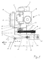
- Fig. 1 is a transmission 1 schematically one Truck shown with an output flange 2, the is provided on the end of an output shaft 3.
- the output shaft 3 provided with the output flange 2 runs in a direction parallel to the direction of travel of the Truck.
- Supply unit can also be a pump, a Act hydraulic pump or a generator.
- the Compressor 5 is together with an air filter 6 Intake damper 7, a pressure silencer 8 and one Air-air cooler 9 on a compressor console 10 arranged.
- the additional element 4 has an articulated shaft 11 and Angular gear 12 on.
- One end of the propeller shaft 11 is connected to the output flange 2 of the transmission 1 and the other end of the propeller shaft 11 is with the Input member 13 of the bevel gear 12 via a Flange 14 connected, the propeller shaft 11 with both the output shaft 3 as well as with the input member 13 of the Angular gear 12 includes a diffraction angle ⁇ .
- the diffraction angle ⁇ is chosen so that it is 15 ° and in particular does not exceed 10 °.
- the diffraction angle ⁇ is chosen so that it is 15 ° and in particular does not exceed 10 °.
- a fan wheel 15 is provided, the is connected to the input member 13 such that it rotates with a rotation of the input member 13 and ensures that the bevel gear 12 is cooled.
- the angular gear 12 has an output member 16 on, which points in the direction of the compressor 5 and thus perpendicular to the output shaft 3 and the Output flange 2 stands.
- a first pulley 17 is provided on the output member 16 on the output member 16 on the output member 16 .
- the Axis of rotation of the drive shaft 19 is perpendicular to Output shaft 3 and thus also perpendicular to the axis of rotation of the output flange 2.
- the Output flange 2, the output member 16 of the Angular gear 12 and the drive shaft 19 such arranged relative to each other that the distance a of Axis of rotation of the output member 16 from the output flange 2 is greater than the distance b of the axis of rotation Drive shaft 19 from the output flange 2.
- first pulley 17 and the second pulley 20 via three V-belts 21 are interconnected.
- the first and the second Form pulley 17 and 20 and the V-belt 21 thus a traction mechanism through which the output member 16 and the drive shaft 19 are connected to each other.
- the traction mechanism can also be used as Chain gear should be designed, instead of Pulleys 17, 20 sprockets are provided are connected to each other via at least one chain.
- the output member 16 is located from the viewpoint of the transmission 1 seen behind the drive shaft 19. With this arrangement of the angular gear 12 relative to the drive shaft 19 together with the pulley 17, 20 and V-belt 21 formed traction mechanism gear runs the cardan shaft 11 almost completely within by the rest Parts of the additional element 4 occupied space.
- the propeller shaft 11 has a sufficient length by the distance between the output flange 2 and Input member 13 perpendicular to the output shaft 3 bridge without the diffraction angle ⁇ a critical area reached above 10 °.
- the transmission 1 If the transmission 1 is operated such that the Turn output shaft 3 and output flange 2, transmits the propeller shaft 11 to the rotary motion Angular gear 12, the output member 15 also in Rotation is offset. About the traction mechanism formed from the pulleys 17, 20 and the V-belts 21, the rotational movement on the drive shaft 19 transferred and thus the compressor 5 driven.
Landscapes
- Engineering & Computer Science (AREA)
- Chemical & Material Sciences (AREA)
- Combustion & Propulsion (AREA)
- Transportation (AREA)
- Mechanical Engineering (AREA)
- Auxiliary Drives, Propulsion Controls, And Safety Devices (AREA)
- Control Of Electric Motors In General (AREA)
- Control Of Multiple Motors (AREA)
- Power Steering Mechanism (AREA)
- Arrangement Or Mounting Of Propulsion Units For Vehicles (AREA)
Abstract
Description
Die Erfindung betrifft ein Zusatzelement für ein
Kraftfahrzeug, insbesondere Lastkraftwagen, mit den
Merkmalen des Oberbegriffes des Anspruches 1.The invention relates to an additional element for a
Motor vehicle, especially trucks, with the
Features of the preamble of
Lastkraftwagen müssen neben den für Kraftfahrzeuge allgemein üblichen Vorrichtungen häufig noch mit Versorgungsaggregaten wie etwa Kompressoren, Pumpen, Hydraulikpumpen oder Generatoren ausgerüstet werden. Derartige Vorrichtungen sind beispielsweise für das Be- und Entladen des Lastkraftwagens notwendig und werden bevorzugt von dem Motor des Lastkraftwagens mechanisch angetrieben. Ansonsten wäre ein weiterer Motor erforderlich. Ein solcher zusätzlicher Motor hätte erhöhte Kosten zur Folge und würde durch sein Eigengewicht das maximal zuladbare Gewicht reduzieren. Daher ist eine derartige Lösung wirtschaftlich nicht sinnvoll.Trucks must be in addition to those for motor vehicles generally common devices still with Supply units such as compressors, pumps, Hydraulic pumps or generators can be equipped. Such devices are for example for loading and unloading the truck necessary and become preferably mechanically by the engine of the truck driven. Otherwise it would be another engine required. Such an additional engine would have increased costs and would be through Dead weight reduce the maximum loadable weight. Therefore, such a solution is not economical meaningful.
Aus der US 5,563,541 ist bekannt, einen Abtriebsflansch des Getriebes direkt mit der Antriebsflansch eines Generators über eine Gelenkwelle zu verbinden. Diese Anordnung setzt einen vergleichsweise großen Abstand zwischen Abtriebsflansch und Antriebsflansch und damit auch der Antriebswelle selbst voraus.From US 5,563,541 it is known an output flange of the gearbox directly with the drive flange To connect the generator via a cardan shaft. This Arrangement sets a comparatively large distance between output flange and drive flange and thus also ahead of the drive shaft itself.
Insbesondere bei Sattelschleppern ergibt sich das Problem, dass der Raum an dem Chassis der Zugmaschine für das Anbringen derartiger Zusatzelemente eng begrenzt ist. Der Raum oberhalb des Chassis hinter der Fahrerkabine wird von dem Auflieger eingenommen, so dass an dieser Stelle keine Zusatzelemente angebracht werden können.This is particularly the case with articulated lorries Problem that the space on the chassis of the tractor for the attachment of such additional elements is narrowly limited. The space above the chassis behind the driver's cabin is taken up by the trailer, so that on this Place no additional elements can be attached.
Der einzig verbleibende Raum ist der unterhalb des Chassis zwischen der Vorder- und der Hinterachse. Allerdings ist bedingt durch den kurzen Radstand sowie die mittig verlaufende Antriebswelle für die Hinterachse auch hier nur vergleichsweise wenig Platz. Dies ist insbesondere auch deswegen der Fall, da in diesem Bereich neben den Zusatzelementen noch ein möglichst großer Kraftstofftank sowie ein Schmierstofftank angebracht werden müssen.The only remaining space is the one below Chassis between the front and rear axles. However, is due to the short wheelbase as well the central drive shaft for the rear axle here too, comparatively little space. This is especially because of this area in addition to the additional elements, the largest possible Fuel tank and a lubricant tank attached Need to become.
Verstärkt wird das Platzproblem, wenn die Hinterachse der Zugmaschine als Zwillingsachse ausgeführt ist, was der Fall ist, wenn das zulässige Gesamtgewicht des Sattelzuges bei über 40 Tonnen liegt. Dann verringert sich der zwischen den Achsen zur Verfügung stehende Raum weiter, da in einem solchen Fall die Gesamtlänge der Zugmaschine nahezu unverändert bleibt.The problem of space is exacerbated when the rear axle of the Tractor is designed as a twin axle, what the The case is when the permissible total weight of the Tractor unit is over 40 tons. Then decreased the space available between the axes further, because in such a case the total length of the Tractor remains almost unchanged.
Der Antrieb der Zusatzelemente erfolgt in der Regel in der Weise, dass das Zusatzelement eine Gelenkwelle aufweist, die mit einem Abtriebsflansch des Getriebes verbunden ist. Eine solche Gelenkwelle ist u.a. deswegen erforderlich, um einerseits das Zusatzelement schwingungstechnisch von dem Rest des Fahrzeugs zu entkoppeln und andererseits eine vergleichsweise einfache Montage bzw. Demontage des Zusatzelements zu ermöglichen.The additional elements are usually driven in the way that the additional element is a cardan shaft has that with an output flange of the transmission connected is. Such a cardan shaft is among others therefore required on the one hand the additional element vibrationally from the rest of the vehicle too decouple and on the other hand a comparatively simple To enable assembly or disassembly of the additional element.
Bei dem Einsatz von Gelenkwellen ist es aber zwingend erforderlich, dass bestimmte Randbedingungen eingehalten werden, da sich sonst die Lebensdauer der Gelenkwellen drastisch reduziert. Insbesondere ist darauf zu achten, dass der sogenannte Beugungswinkel der Gelenkwelle in Abhängigkeit von der Drehzahl einen bestimmten Wert nicht überschreitet.When using cardan shafts, however, it is imperative required that certain boundary conditions are met otherwise the life of the cardan shafts drastically reduced. Particular attention should be paid to that the so-called diffraction angle of the propeller shaft in Dependence on the speed does not have a certain value exceeds.
Aus dieser winkelbedingten Randbedingung ergibt sich Folgendes. Bei einem bestimmten Abstand zwischen der Drehachse des Abtriebsflansches am Getriebe und der Drehachse des Antriebsflansches am Zusatzelement ist ein Mindestabstand zwischen dem Abtriebsflansch und dem Antriebsflansch in Richtung der Drehachse des Antriebsflansches, also in der Regel in Fahrtrichtung des Fahrzeuges, festgelegt. Dieser Mindestabstand führt aber häufig zu Konflikten mit dem zur Verfügung stehenden Platz unterhalb des Chassis. Außerdem wird durch die Gelenkwelle weiterer Raum verbaut, der sonst anderweitig genutzt werden könnte.From this angular constraint results A. At a certain distance between the Axis of rotation of the output flange on the gearbox and the The axis of rotation of the drive flange on the additional element is a Minimum distance between the output flange and the Drive flange in the direction of the axis of rotation of the Drive flange, so usually in the direction of travel Vehicle. This minimum distance leads often conflicts with the available Space below the chassis. In addition, the PTO shaft installed more space that otherwise otherwise could be used.
Der Erfindung liegt daher das technische Problem
zugrunde, ein Zusatzelement gemäß dem Oberbegriff des
Anspruchs 1 bereitzustellen, das möglichst platzsparend
und in einem geringen Abstand zu dem Getriebe mittels
einer Gelenkwelle mit diesem verbunden werden kann und
durch den Motor des Kraftfahrzeugs mechanisch angetrieben
wird.The invention therefore has the technical problem
based on an additional element according to the preamble of
Dieses technische Problem wird dadurch gelöst, dass die Drehachse des Abtriebsflansches und die Drehachse der Antriebswelle im Wesentlichen senkrecht zueinander ausgerichtet und beabstandet zueinander angeordnet sind, dass ein Winkelgetriebe vorgesehen ist, dass die Gelenkwelle das Getriebe mit dem Eingangsglied des Winkelgetriebes verbindet, dass die Antriebswelle und das Ausgangsglied des Winkelgetriebes über ein Zugmittelgetriebe miteinander verbunden sind, dass das Winkelgetriebe und das Zugmittelgetriebe die Drehbewegung der Gelenkwelle auf die Antriebswelle übertragen und dass der Abstand der Drehachse des Ausgangsglieds des Winkelgetriebes vom Abtriebsflansch größer als der Abstand der Drehachse der Antriebswelle vom Abtriebsflansch ist.This technical problem is solved in that the Axis of rotation of the output flange and the axis of rotation of the Drive shaft essentially perpendicular to each other aligned and spaced from each other, that an angular gear is provided that the PTO shaft the transmission with the input member of the Angular gear connects that the drive shaft and that Output element of the angular gear via Traction gearboxes are interconnected that the Angular gear and the traction mechanism the rotary movement the PTO shaft to the drive shaft and that the distance of the axis of rotation of the output member of the Angular gear from the output flange larger than that Distance of the axis of rotation of the drive shaft from Output flange is.
Erfindungsgemäß ist erkannt worden, dass durch diese Anordnung des Winkelgetriebes relativ zur Antriebswelle zusammen mit dem Zugmittelgetriebe die Gelenkwelle nahezu vollständig innerhalb des durch die restlichen Teile des Zusatzelementes eingenommenen Raumes verläuft und nicht seitlich darüber oder daneben hinausragt. Es bleibt damit gewährleistet, dass die Gelenkwelle eine hinreichende Länge hat, um den Abstand des Abtriebsflansches und des Eingangsgliedes senkrecht zu der Drehachse des Abtriebsflansches zu überbrücken, ohne dass der Beugungswinkel einen kritischen Bereich größer 10°, insbesondere größer 15°, erreicht.According to the invention, it has been recognized that through this Arrangement of the bevel gear relative to the drive shaft almost together with the traction mechanism gearbox completely within the through the remaining parts of the Additional element occupied space runs and not protrudes laterally above or next to it. It stays that way ensures that the propeller shaft is adequate Length has to the distance between the output flange and Input member perpendicular to the axis of rotation of the To bridge the output flange without the Diffraction angle a critical area greater than 10 °, in particular greater than 15 °.
Dadurch, dass die Antriebswelle des Versorgungsaggregats senkrecht zum Abtriebsflansch des Getriebes, also quer zur Drehachse des Abtriebsflansches angeordnet ist und damit senkrecht zur Fahrtrichtung steht, ist ein platzsparender Einbau des Versorgungsaggregats möglich. Der durch das Zusatzelement eingenommene Raum kann minimiert werden, da die Längserstreckung des Versorgungsaggregates in der Regel größer als die Quererstreckung ist.The fact that the drive shaft of the supply unit perpendicular to the gearbox output flange, i.e. across is arranged to the axis of rotation of the output flange and so that it is perpendicular to the direction of travel is a space-saving installation of the supply unit possible. The space occupied by the additional element can be minimized since the longitudinal extension of the Supply units are generally larger than that Is transverse extension.
Durch eine Variation der Länge der Antriebswelle des
Versorgungsaggregats und der Länge des Zugmittels
(Riemen, Kette) kann zudem in einfacher Weise das
Zusatzelement an die baulichen Gegebenheiten
unterschiedlicher Fahrzeugtypen angepasst werden.
Das Zugmittelgetriebe als Riemengetriebe mit einer ersten
Riemenscheibe und einer zweiten, mit der Antriebswelle
verbundenen Riemenscheibe auszubilden, führt zunächst zu
einer einfachen und damit kostengünstigen Lösung.
Außerdem kann das Zusatzelement durch Längenänderung des
Keilriemens oder Zahnriemens leicht an unterschiedliche
Fahrzeugtypen angepasst werden.By varying the length of the drive shaft of the supply unit and the length of the traction means (belt, chain), the additional element can also be easily adapted to the structural conditions of different vehicle types.
Designing the traction mechanism transmission as a belt transmission with a first belt pulley and a second belt pulley connected to the drive shaft initially leads to a simple and therefore inexpensive solution. In addition, the additional element can be easily adapted to different vehicle types by changing the length of the V-belt or toothed belt.
Ist ein großer Kraftschluss zwischen dem Getriebe auf der einen Seite und dem Zusatzelement auf der anderen Seite erforderlich, kann das Zugmittelgetriebe auch als ein Kettengetriebe ausgebildet sein.There is a large frictional connection between the gearbox on the one side and the additional element on the other side required, the traction mechanism can also be used as a Chain gear should be designed.
Die in dem Zusatzelement angeordneten Versorgungsaggregate können ein Kompressor, eine Pumpe, insbesondere Hydraulikpumpe sowie ein Generator sein.The arranged in the additional element Supply units can be a compressor, a pump, especially hydraulic pump and a generator.
Insbesondere bei hohen Drehzahlen ist es vorteilhaft, wenn an der dem Eingangsglied des Winkelgetriebes gegenüberliegenden Seite ein Lüfterrad vorgesehen ist, das mit angetrieben wird. Damit wird das Getriebe gekühlt um zu verhindern, dass die Temperatur des Getriebeöls einen kritischen Wert überschreitet und das Winkelgetriebe Schaden nimmt.Especially at high speeds, it is advantageous if on the input member of the bevel gear opposite side a fan wheel is provided that is driven with. This cools the gearbox to prevent the temperature of the gear oil exceeds a critical value and that Angular gearbox is damaged.
Um eine hinreichende Kühlung des Getriebeöls zu gewährleisten, ist es außerdem vorteilhaft, dass Gehäuse des Winkelgetriebes mit Kühlrippen zu versehen.To ensure adequate cooling of the gear oil ensure, it is also beneficial that housing to provide the angular gear with cooling fins.
Um große Belastungen der Antriebswelle senkrecht zu ihrer Erstreckungsrichtung zu vermeiden und zwar insbesondere dann, wenn diese eine große Länge aufweist, ist es vorteilhaft, ein Lager nahe des Zugmittelgetriebes vorzusehen.To large loads on the drive shaft perpendicular to it Avoid extension direction and in particular then if it is long, it is advantageous, a camp near the traction mechanism provided.
Die vorliegende Erfindung wird nachfolgend anhand einer nur ein bevorzugtes Ausführungsbeispiel darstellenden Zeichnung erläutert. Dabei zeigt die
- Fig. 1
- die Draufsicht auf ein erfindungsgemäßes Zusatzelement.
- Fig. 1
- the top view of an additional element according to the invention.
In der Fig. 1 ist schematisch ein Getriebe 1 eines
Lastkraftwagens gezeigt mit einem Abtriebsflansch 2, der
auf dem Ende einer Abtriebswelle 3 vorgesehen ist. Die
mit dem Abtriebsflansch 2 versehene Abtriebswelle 3
verläuft in einer Richtung parallel zur Fahrtrichtung des
Lastkraftwagens. Seitlich versetzt zu dem Getriebe 1 ist
das Zusatzelement 4 vorgesehen, das als
Versorgungsaggregat einen Kompressor 5 aufweist. Bei dem
Versorgungsaggregat kann es sich auch um eine Pumpe, eine
Hydraulikpumpe oder einen Generator handeln. Der
Kompressor 5 ist zusammen mit einem Luftfilter 6, einem
Ansaugdämpfer 7, einem Druckschalldämpfer 8 und einem
Luft-Luftkühler 9 auf einer Kompressorkonsole 10
angeordnet.In Fig. 1 is a
Das Zusatzelement 4 weist eine Gelenkwelle 11 und ein
Winkelgetriebe 12 auf. Das eine Ende der Gelenkwelle 11
ist mit dem Abtriebsflansch 2 des Getriebes 1 verbunden
und das andere Ende der Gelenkwelle 11 ist mit dem
Eingangsglied 13 des Winkelgetriebes 12 über einen
Flansch 14 verbunden, wobei die Gelenkwelle 11 sowohl mit
der Abtriebswelle 3 als auch mit dem Eingangsglied 13 des
Winkelgetriebes 12 einen Beugungswinkel α einschließt. The
Der Beugungswinkel α ist dabei so gewählt, dass er 15°
und insbesondere 10° nicht überschreitet. Durch die
Gelenkwelle 11 wird eine schwingungstechnische
Entkoppelung von Zusatzelement 4 und Motorblock
einschließlich Getriebe 1 erreicht. Außerdem wird durch
die Gelenkwelle 11 eine einfache Montage des
Zusatzelements 4 an einem Lastkraftwagen ermöglicht.The diffraction angle α is chosen so that it is 15 °
and in particular does not exceed 10 °. Through the
PTO shaft 11 becomes a vibration
Decoupling
An der dem Eingangsglied 13 gegenüberliegenden Seite des
Winkelgetriebes 12 ist ein Lüfterrad 15 vorgesehen, das
derart mit dem Eingangsglied 13 verbunden ist, dass es
bei einer Drehung des Eingangsgliedes 13 mitdreht und
dafür sorgt, dass das Winkelgetriebe 12 gekühlt wird.
Außerdem weist das Winkelgetriebe 12 ein Ausgangsglied 16
auf, das in die Richtung des Kompressors 5 weist und
damit senkrecht zur Abtriebswelle 3 und dem
Abtriebsflansch 2 steht. Auf dem Ausgangsglied 16 ist
eine erste Riemenscheibe 17 vorgesehen.On the side of the
Mit dem Kompressor 5 über eine Kupplung 18 verbunden ist
eine Antriebswelle 19, wobei die Antriebswelle 19 eine
Drehbewegung auf den Kompressor 5 übertragen kann. Die
Drehachse der Antriebswelle 19 steht senkrecht zur
Abtriebswelle 3 und damit auch senkrecht zur Drehachse
des Abtriebsflansches 2. Außerdem sind der
Abtriebsflansch 2, das Ausgangsglied 16 des
Winkelgetriebes 12 und die Antriebswelle 19 derart
relativ zueinander angeordnet, dass der Abstand a der
Drehachse des Ausgangsgliedes 16 vom Abtriebsflansch 2
größer ist, als der Abstand b der Drehachse der
Antriebswelle 19 vom Abtriebsflansch 2. Is connected to the
Auf dem von dem Kompressor 5 abgewandten Ende der
Antriebswelle 19 ist eine zweite Riemenscheibe 20
vorgesehen, wobei die erste Riemenscheibe 17 und die
zweite Riemenscheibe 20 über drei Keilriemen 21
miteinander verbunden sind. Die erste und die zweite
Riemenscheibe 17 und 20 und die Keilriemen 21 bilden
damit ein Zugmittelgetriebe, durch das das Ausgangsglied
16 und die Antriebswelle 19 miteinander verbunden sind.
Alternativ kann das Zugmittelgetriebe auch als
Kettengetriebe ausgebildet sein, wobei statt der
Riemenscheiben 17, 20 Kettenräder vorgesehen sind, die
über wenigstens eine Kette miteinander verbunden sind.On the end facing away from the
Durch das Zugmittelgetriebe kann der Abstand zwischen
Abtriebsflansch 2 und Antriebswelle 19 an
unterschiedliche Fahrzeugtypen in der Weise angepasst
werden, dass die Länge des Zugmittels (Keilriemen 21)
variiert wird.The distance between
Das Ausgangsglied 16 liegt aus Sicht des Getriebes 1
gesehen hinter der Antriebswelle 19. Bei dieser Anordnung
des Winkelgetriebes 12 relativ zur Antriebswelle 19
zusammen mit dem aus Riemenscheiben 17, 20 und Keilriemen
21 gebildeten Zugmittelgetriebe verläuft die Gelenkwelle
11 nahezu vollständig innerhalb des durch die restlichen
Teile des Zusatzelementes 4 eingenommenen Raumes.
Außerdem hat die Gelenkwelle 11 eine hinreichende Länge,
um den Abstand des Abtriebsflansches 2 und des
Eingangsgliedes 13 senkrecht zur Abtriebswelle 3 zu
überbrücken, ohne dass der Beugungswinkel α einen
kritischen Bereich oberhalb von 10° erreicht. The
Durch das Winkelgetriebe 12 und das Zugmittelgetriebe
kann die Welle 22 des Kompressors 5 senkrecht zur
Abtriebswelle und damit senkrecht zur Fahrtrichtung
(Pfeil A) verlaufen. Dies ermöglicht den Einbau des
Kompressors 5 senkrecht zur Fahrtrichtung A, was zu einer
weiteren Platzersparnis führt, da die Längserstreckung
des Kompressors 5 geringer als die Quererstreckung ist.Through the
Auf der Kompressorkonsole 10 ist außerdem ein Lager 23
für die Antriebswelle 19 vorgesehen, durch das die
Antriebswelle 19 nahe der zweiten Riemenscheibe 20
gelagert wird, um Belastungen senkrecht zur Antriebswelle
19 aufgrund der Spannung der Keilriemen 21 zu vermeiden.There is also a
Wird das Getriebe 1 derart betätigt, dass sich die
Abtriebswelle 3 und der Abtriebsflansch 2 drehen,
überträgt die Gelenkwelle 11 die Drehbewegung auf das
Winkelgetriebe 12, dessen Ausgangsglied 15 ebenfalls in
Drehung versetzt wird. Über das Zugmittelgetriebe
gebildet aus den Riemenscheiben 17, 20 und den Keilriemen
21 wird die Drehbewegung auf die Antriebswelle 19
übertragen und damit der Kompressor 5 angetrieben.If the
Claims (15)
dadurch gekennzeichnet, dass das Zugmittelgetriebe (17, 20, 21) als Riemengetriebe ausgebildet ist.Additional element according to claim 1,
characterized in that the traction mechanism transmission (17, 20, 21) is designed as a belt transmission.
dadurch gekennzeichnet, dass das Riemengetriebe am Ausgangsglied (16) des Winkelgetriebes (12) eine erste Riemenscheibe (17) und auf der Antriebswelle (19) eine zweite Riemenscheibe (20) aufweist.Additional element according to claim 2,
characterized in that the belt transmission has a first belt pulley (17) on the output member (16) of the angular transmission (12) and a second belt pulley (20) on the drive shaft (19).
dadurch gekennzeichnet, dass die erste und die zweite Riemenscheibe (17, 20) mit mindestens einem Keilriemen (21) miteinander verbunden sind.Additional element according to claim 3,
characterized in that the first and second pulleys (17, 20) are connected to one another by at least one V-belt (21).
dadurch gekennzeichnet, dass die erste und die zweite Riemenscheibe (17, 20) mit mindestens einem Zahnriemen miteinander verbunden sind. Additional element according to claim 3,
characterized in that the first and the second pulley (17, 20) are connected to one another by at least one toothed belt.
dadurch gekennzeichnet, dass das Zugmittelgetriebe als Kettengetriebe ausgebildet ist.Additional element according to claim 1,
characterized in that the traction mechanism gear is designed as a chain gear.
dadurch gekennzeichnet, dass das Kettengetriebe am Ausgangsglied (16) des Winkelgetriebes (12) ein erstes Kettenrad und auf der Antriebswelle (19) ein zweites Kettenrad aufweist.Additional element according to claim 6,
characterized in that the chain gear has a first sprocket on the output member (16) of the angular gear (12) and a second sprocket on the drive shaft (19).
dadurch gekennzeichnet, dass das erste und das zweite Kettenrad mit mindestens einer Kette miteinander verbunden sind.Additional element according to claim 7,
characterized in that the first and second sprockets are connected to each other with at least one chain.
dadurch gekennzeichnet, dass das Versorgungsaggregat als Kompressor (5) ausgebildet ist.Additional element according to one of claims 1 to 8,
characterized in that the supply unit is designed as a compressor (5).
dadurch gekennzeichnet, dass das Versorgungsaggregat als Pumpe, insbesondere Hydraulikpumpe, ausgebildet ist.Additional element according to one of claims 1 to 8,
characterized in that the supply unit is designed as a pump, in particular a hydraulic pump.
dadurch gekennzeichnet, dass das Versorgungsaggregat als Generator ausgebildet ist. Additional element according to one of claims 1 to 8,
characterized in that the supply unit is designed as a generator.
dadurch gekennzeichnet, dass das Winkelgetriebe (12) an der dem Eingangsglied (13) gegenüberliegenden Seite ein Lüfterrad (15) aufweist.Additional element according to one of claims 1 to 11,
characterized in that the angular gear (12) has a fan wheel (15) on the side opposite the input member (13).
dadurch gekennzeichnet, dass das Winkelgetriebe (12) Kühlrippen aufweist.Additional element according to one of claims 1 to 12,
characterized in that the angular gear (12) has cooling fins.
dadurch gekennzeichnet, dass der Beugungswinkel α der Gelenkwelle (11) kleiner als 15° ist, vorzugsweise kleiner 10° ist.Additional element according to one of claims 1 to 13,
characterized in that the diffraction angle α of the propeller shaft (11) is less than 15 °, preferably less than 10 °.
dadurch gekennzeichnet, dass ein Lager (23) für die Antriebswelle (19) nahe dem Zugmittelgetriebe vorgesehen ist.Additional element according to one of claims 1 to 14,
characterized in that a bearing (23) for the drive shaft (19) is provided near the traction mechanism.
Priority Applications (5)
| Application Number | Priority Date | Filing Date | Title |
|---|---|---|---|
| ES03001461T ES2256599T3 (en) | 2003-01-22 | 2003-01-22 | ADDITIONAL ELEMENT ACTUATED FOR A CAR. |
| DE50301607T DE50301607D1 (en) | 2003-01-22 | 2003-01-22 | Powered additional element on a motor vehicle |
| EP03001461A EP1440835B1 (en) | 2003-01-22 | 2003-01-22 | Auxiliary drive for a vehicle |
| AT03001461T ATE309108T1 (en) | 2003-01-22 | 2003-01-22 | DRIVEN ADDITIONAL ELEMENT ON A MOTOR VEHICLE |
| GB0305193A GB2389087B (en) | 2003-01-22 | 2003-03-06 | Powered auxiliary element on a motor vehicle |
Applications Claiming Priority (1)
| Application Number | Priority Date | Filing Date | Title |
|---|---|---|---|
| EP03001461A EP1440835B1 (en) | 2003-01-22 | 2003-01-22 | Auxiliary drive for a vehicle |
Publications (2)
| Publication Number | Publication Date |
|---|---|
| EP1440835A1 true EP1440835A1 (en) | 2004-07-28 |
| EP1440835B1 EP1440835B1 (en) | 2005-11-09 |
Family
ID=8185865
Family Applications (1)
| Application Number | Title | Priority Date | Filing Date |
|---|---|---|---|
| EP03001461A Expired - Lifetime EP1440835B1 (en) | 2003-01-22 | 2003-01-22 | Auxiliary drive for a vehicle |
Country Status (5)
| Country | Link |
|---|---|
| EP (1) | EP1440835B1 (en) |
| AT (1) | ATE309108T1 (en) |
| DE (1) | DE50301607D1 (en) |
| ES (1) | ES2256599T3 (en) |
| GB (1) | GB2389087B (en) |
Families Citing this family (2)
| Publication number | Priority date | Publication date | Assignee | Title |
|---|---|---|---|---|
| ITUB20159734A1 (en) * | 2015-12-22 | 2017-06-22 | Pierangelo Vercellino | Vehicle with trailer, operatively connected to it by means of a cardan shaft |
| RU2688106C1 (en) * | 2017-06-20 | 2019-05-17 | Дамир Мугаллимович Хабибуллин | Power take-off from transfer gearbox |
Citations (3)
| Publication number | Priority date | Publication date | Assignee | Title |
|---|---|---|---|---|
| US2766628A (en) * | 1954-11-15 | 1956-10-16 | Wilson John Hart | Power take-off for trucks |
| US5563541A (en) | 1994-05-19 | 1996-10-08 | Sony/Tektronix Corporation | Load current detection circuit |
| DE20214999U1 (en) * | 2002-03-22 | 2002-12-19 | Schuebler Fahrzeugtechnik Gmbh | Driven additional element on a motor vehicle |
Family Cites Families (1)
| Publication number | Priority date | Publication date | Assignee | Title |
|---|---|---|---|---|
| CA2146394A1 (en) * | 1995-04-05 | 1996-10-06 | Kazutoshi Furukawa | Power supply apparatus installed under a carrier of a vehicle |
-
2003
- 2003-01-22 ES ES03001461T patent/ES2256599T3/en not_active Expired - Lifetime
- 2003-01-22 AT AT03001461T patent/ATE309108T1/en not_active IP Right Cessation
- 2003-01-22 EP EP03001461A patent/EP1440835B1/en not_active Expired - Lifetime
- 2003-01-22 DE DE50301607T patent/DE50301607D1/en not_active Expired - Lifetime
- 2003-03-06 GB GB0305193A patent/GB2389087B/en not_active Expired - Fee Related
Patent Citations (3)
| Publication number | Priority date | Publication date | Assignee | Title |
|---|---|---|---|---|
| US2766628A (en) * | 1954-11-15 | 1956-10-16 | Wilson John Hart | Power take-off for trucks |
| US5563541A (en) | 1994-05-19 | 1996-10-08 | Sony/Tektronix Corporation | Load current detection circuit |
| DE20214999U1 (en) * | 2002-03-22 | 2002-12-19 | Schuebler Fahrzeugtechnik Gmbh | Driven additional element on a motor vehicle |
Also Published As
| Publication number | Publication date |
|---|---|
| GB0305193D0 (en) | 2003-04-09 |
| GB2389087B (en) | 2004-06-02 |
| ATE309108T1 (en) | 2005-11-15 |
| DE50301607D1 (en) | 2005-12-15 |
| GB2389087A (en) | 2003-12-03 |
| ES2256599T3 (en) | 2006-07-16 |
| EP1440835B1 (en) | 2005-11-09 |
Similar Documents
| Publication | Publication Date | Title |
|---|---|---|
| DE60104318T2 (en) | DRIVE TRAIN | |
| DE1963019A1 (en) | Drive for motor vehicles | |
| DE102005017754A1 (en) | Construction machine, in particular road milling machine, recycler or stabilizer, and drive train for such construction machines | |
| DE4027901A1 (en) | ALL-WHEEL DRIVE MOTOR VEHICLE OF THE TYPE WITH CROSS-MOUNTED ENGINE | |
| EP3647097A1 (en) | Motor vehicle drive | |
| DE4207193A1 (en) | ASSEMBLY STRUCTURE FOR A VEHICLE POWER TRANSMISSION UNIT | |
| DE2106366A1 (en) | Motor vehicle powered by a rotating piston engine | |
| DE60223643T2 (en) | Horizontal gear and lubrication system for telescopic cranes | |
| DE102018204910A1 (en) | PTO arrangement | |
| DE2948195A1 (en) | TRANSMISSION AS MAIN DRIVE FOR A VEHICLE DRIVEN BY AN INTERNAL COMBUSTION ENGINE | |
| DE4143102A1 (en) | POWER TRANSMISSION PART FOR A MOTOR VEHICLE | |
| EP1346867B1 (en) | Driven auxiliary device on a motor vehicle | |
| EP1440835B1 (en) | Auxiliary drive for a vehicle | |
| EP3115242B1 (en) | Ventilator drive for a motor vehicle | |
| DE2659282A1 (en) | MOTOR VEHICLE WITH AN INTERNAL COMBUSTION ENGINE | |
| DE2803840A1 (en) | POWER PLANT FOR A MOTOR VEHICLE | |
| EP3831635A1 (en) | Power train for an agricultural working machine | |
| DE19841590A1 (en) | Arrangement and drive connection of auxiliary units to diesel engine has single or twin-staged planetary gear brought together with at least two different auxiliary units | |
| DE102011118111A1 (en) | Drivetrain for driving internal combustion engine of lorry, has hydraulic pump conveying hydraulic medium and driven by axle differential, which includes plate wheel for introducing rotational torque of drive motor into axle differential | |
| DE69919958T2 (en) | Tractor with lubrication system | |
| DE102015220888A1 (en) | PTO head | |
| EP0648638B1 (en) | Driving combination | |
| DE4111983B4 (en) | Drive unit for a vehicle | |
| DE4118266A1 (en) | Four wheel drive transmission system - is for transverse engine and controls distribution of power to front and rear axle | |
| EP1468861B1 (en) | Driven attachment with accessory device for motor vehicle |
Legal Events
| Date | Code | Title | Description |
|---|---|---|---|
| PUAI | Public reference made under article 153(3) epc to a published international application that has entered the european phase |
Free format text: ORIGINAL CODE: 0009012 |
|
| AK | Designated contracting states |
Kind code of ref document: A1 Designated state(s): AT BE BG CH CY CZ DE DK EE ES FI FR GB GR HU IE IT LI LU MC NL PT SE SI SK TR |
|
| AX | Request for extension of the european patent |
Extension state: AL LT LV MK RO |
|
| RAP1 | Party data changed (applicant data changed or rights of an application transferred) |
Owner name: PONTE VECCHIO CONSULT SAGL |
|
| 17P | Request for examination filed |
Effective date: 20041004 |
|
| 17Q | First examination report despatched |
Effective date: 20041208 |
|
| AKX | Designation fees paid |
Designated state(s): AT BE BG CH CY CZ DE DK EE ES FI FR GB GR HU IE IT LI LU MC NL PT SE SI SK TR |
|
| GRAP | Despatch of communication of intention to grant a patent |
Free format text: ORIGINAL CODE: EPIDOSNIGR1 |
|
| GRAS | Grant fee paid |
Free format text: ORIGINAL CODE: EPIDOSNIGR3 |
|
| GRAA | (expected) grant |
Free format text: ORIGINAL CODE: 0009210 |
|
| AK | Designated contracting states |
Kind code of ref document: B1 Designated state(s): AT BE BG CH CY CZ DE DK EE ES FI FR GB GR HU IE IT LI LU MC NL PT SE SI SK TR |
|
| PG25 | Lapsed in a contracting state [announced via postgrant information from national office to epo] |
Ref country code: SI Free format text: LAPSE BECAUSE OF FAILURE TO SUBMIT A TRANSLATION OF THE DESCRIPTION OR TO PAY THE FEE WITHIN THE PRESCRIBED TIME-LIMIT Effective date: 20051109 Ref country code: FI Free format text: LAPSE BECAUSE OF FAILURE TO SUBMIT A TRANSLATION OF THE DESCRIPTION OR TO PAY THE FEE WITHIN THE PRESCRIBED TIME-LIMIT Effective date: 20051109 Ref country code: IE Free format text: LAPSE BECAUSE OF FAILURE TO SUBMIT A TRANSLATION OF THE DESCRIPTION OR TO PAY THE FEE WITHIN THE PRESCRIBED TIME-LIMIT Effective date: 20051109 Ref country code: GB Free format text: LAPSE BECAUSE OF FAILURE TO SUBMIT A TRANSLATION OF THE DESCRIPTION OR TO PAY THE FEE WITHIN THE PRESCRIBED TIME-LIMIT Effective date: 20051109 Ref country code: SK Free format text: LAPSE BECAUSE OF FAILURE TO SUBMIT A TRANSLATION OF THE DESCRIPTION OR TO PAY THE FEE WITHIN THE PRESCRIBED TIME-LIMIT Effective date: 20051109 Ref country code: CZ Free format text: LAPSE BECAUSE OF FAILURE TO SUBMIT A TRANSLATION OF THE DESCRIPTION OR TO PAY THE FEE WITHIN THE PRESCRIBED TIME-LIMIT Effective date: 20051109 Ref country code: IT Free format text: LAPSE BECAUSE OF FAILURE TO SUBMIT A TRANSLATION OF THE DESCRIPTION OR TO PAY THE FEE WITHIN THE PRESCRIBED TIME-LIMIT;WARNING: LAPSES OF ITALIAN PATENTS WITH EFFECTIVE DATE BEFORE 2007 MAY HAVE OCCURRED AT ANY TIME BEFORE 2007. THE CORRECT EFFECTIVE DATE MAY BE DIFFERENT FROM THE ONE RECORDED. Effective date: 20051109 |
|
| REG | Reference to a national code |
Ref country code: GB Ref legal event code: FG4D Free format text: NOT ENGLISH |
|
| REG | Reference to a national code |
Ref country code: CH Ref legal event code: EP |
|
| REG | Reference to a national code |
Ref country code: IE Ref legal event code: FG4D Free format text: LANGUAGE OF EP DOCUMENT: GERMAN |
|
| REF | Corresponds to: |
Ref document number: 50301607 Country of ref document: DE Date of ref document: 20051215 Kind code of ref document: P |
|
| PG25 | Lapsed in a contracting state [announced via postgrant information from national office to epo] |
Ref country code: MC Free format text: LAPSE BECAUSE OF NON-PAYMENT OF DUE FEES Effective date: 20060131 Ref country code: LU Free format text: LAPSE BECAUSE OF NON-PAYMENT OF DUE FEES Effective date: 20060131 |
|
| PG25 | Lapsed in a contracting state [announced via postgrant information from national office to epo] |
Ref country code: SE Free format text: LAPSE BECAUSE OF FAILURE TO SUBMIT A TRANSLATION OF THE DESCRIPTION OR TO PAY THE FEE WITHIN THE PRESCRIBED TIME-LIMIT Effective date: 20060209 Ref country code: GR Free format text: LAPSE BECAUSE OF FAILURE TO SUBMIT A TRANSLATION OF THE DESCRIPTION OR TO PAY THE FEE WITHIN THE PRESCRIBED TIME-LIMIT Effective date: 20060209 Ref country code: DK Free format text: LAPSE BECAUSE OF FAILURE TO SUBMIT A TRANSLATION OF THE DESCRIPTION OR TO PAY THE FEE WITHIN THE PRESCRIBED TIME-LIMIT Effective date: 20060209 Ref country code: BG Free format text: LAPSE BECAUSE OF FAILURE TO SUBMIT A TRANSLATION OF THE DESCRIPTION OR TO PAY THE FEE WITHIN THE PRESCRIBED TIME-LIMIT Effective date: 20060209 |
|
| PG25 | Lapsed in a contracting state [announced via postgrant information from national office to epo] |
Ref country code: PT Free format text: LAPSE BECAUSE OF FAILURE TO SUBMIT A TRANSLATION OF THE DESCRIPTION OR TO PAY THE FEE WITHIN THE PRESCRIBED TIME-LIMIT Effective date: 20060410 |
|
| REG | Reference to a national code |
Ref country code: CH Ref legal event code: NV Representative=s name: TROESCH SCHEIDEGGER WERNER AG |
|
| PG25 | Lapsed in a contracting state [announced via postgrant information from national office to epo] |
Ref country code: HU Free format text: LAPSE BECAUSE OF FAILURE TO SUBMIT A TRANSLATION OF THE DESCRIPTION OR TO PAY THE FEE WITHIN THE PRESCRIBED TIME-LIMIT Effective date: 20060510 |
|
| GBV | Gb: ep patent (uk) treated as always having been void in accordance with gb section 77(7)/1977 [no translation filed] |
Effective date: 20051109 |
|
| REG | Reference to a national code |
Ref country code: IE Ref legal event code: FD4D |
|
| REG | Reference to a national code |
Ref country code: ES Ref legal event code: FG2A Ref document number: 2256599 Country of ref document: ES Kind code of ref document: T3 |
|
| ET | Fr: translation filed | ||
| PLBE | No opposition filed within time limit |
Free format text: ORIGINAL CODE: 0009261 |
|
| STAA | Information on the status of an ep patent application or granted ep patent |
Free format text: STATUS: NO OPPOSITION FILED WITHIN TIME LIMIT |
|
| 26N | No opposition filed |
Effective date: 20060810 |
|
| PGFP | Annual fee paid to national office [announced via postgrant information from national office to epo] |
Ref country code: CH Payment date: 20080129 Year of fee payment: 6 Ref country code: ES Payment date: 20080201 Year of fee payment: 6 |
|
| PGFP | Annual fee paid to national office [announced via postgrant information from national office to epo] |
Ref country code: NL Payment date: 20080130 Year of fee payment: 6 |
|
| PG25 | Lapsed in a contracting state [announced via postgrant information from national office to epo] |
Ref country code: EE Free format text: LAPSE BECAUSE OF FAILURE TO SUBMIT A TRANSLATION OF THE DESCRIPTION OR TO PAY THE FEE WITHIN THE PRESCRIBED TIME-LIMIT Effective date: 20051109 |
|
| PGFP | Annual fee paid to national office [announced via postgrant information from national office to epo] |
Ref country code: AT Payment date: 20080129 Year of fee payment: 6 |
|
| PG25 | Lapsed in a contracting state [announced via postgrant information from national office to epo] |
Ref country code: TR Free format text: LAPSE BECAUSE OF FAILURE TO SUBMIT A TRANSLATION OF THE DESCRIPTION OR TO PAY THE FEE WITHIN THE PRESCRIBED TIME-LIMIT Effective date: 20051109 |
|
| PGFP | Annual fee paid to national office [announced via postgrant information from national office to epo] |
Ref country code: FR Payment date: 20080129 Year of fee payment: 6 |
|
| PGFP | Annual fee paid to national office [announced via postgrant information from national office to epo] |
Ref country code: BE Payment date: 20080304 Year of fee payment: 6 |
|
| PG25 | Lapsed in a contracting state [announced via postgrant information from national office to epo] |
Ref country code: CY Free format text: LAPSE BECAUSE OF FAILURE TO SUBMIT A TRANSLATION OF THE DESCRIPTION OR TO PAY THE FEE WITHIN THE PRESCRIBED TIME-LIMIT Effective date: 20051109 |
|
| REG | Reference to a national code |
Ref country code: CH Ref legal event code: PL |
|
| NLV4 | Nl: lapsed or anulled due to non-payment of the annual fee |
Effective date: 20090801 |
|
| PG25 | Lapsed in a contracting state [announced via postgrant information from national office to epo] |
Ref country code: CH Free format text: LAPSE BECAUSE OF NON-PAYMENT OF DUE FEES Effective date: 20090131 Ref country code: LI Free format text: LAPSE BECAUSE OF NON-PAYMENT OF DUE FEES Effective date: 20090131 Ref country code: AT Free format text: LAPSE BECAUSE OF NON-PAYMENT OF DUE FEES Effective date: 20090122 |
|
| REG | Reference to a national code |
Ref country code: FR Ref legal event code: ST Effective date: 20091030 |
|
| PG25 | Lapsed in a contracting state [announced via postgrant information from national office to epo] |
Ref country code: NL Free format text: LAPSE BECAUSE OF NON-PAYMENT OF DUE FEES Effective date: 20090801 |
|
| PG25 | Lapsed in a contracting state [announced via postgrant information from national office to epo] |
Ref country code: BE Free format text: LAPSE BECAUSE OF NON-PAYMENT OF DUE FEES Effective date: 20090131 |
|
| REG | Reference to a national code |
Ref country code: ES Ref legal event code: FD2A Effective date: 20090123 |
|
| PG25 | Lapsed in a contracting state [announced via postgrant information from national office to epo] |
Ref country code: ES Free format text: LAPSE BECAUSE OF NON-PAYMENT OF DUE FEES Effective date: 20090123 Ref country code: FR Free format text: LAPSE BECAUSE OF NON-PAYMENT OF DUE FEES Effective date: 20090202 |
|
| PGFP | Annual fee paid to national office [announced via postgrant information from national office to epo] |
Ref country code: DE Payment date: 20100122 Year of fee payment: 8 |
|
| REG | Reference to a national code |
Ref country code: DE Ref legal event code: R119 Ref document number: 50301607 Country of ref document: DE Effective date: 20110802 |
|
| PG25 | Lapsed in a contracting state [announced via postgrant information from national office to epo] |
Ref country code: DE Free format text: LAPSE BECAUSE OF NON-PAYMENT OF DUE FEES Effective date: 20110802 |