EP1440802A2 - Cylindre de sérigrafie - Google Patents
Cylindre de sérigrafie Download PDFInfo
- Publication number
- EP1440802A2 EP1440802A2 EP04101719A EP04101719A EP1440802A2 EP 1440802 A2 EP1440802 A2 EP 1440802A2 EP 04101719 A EP04101719 A EP 04101719A EP 04101719 A EP04101719 A EP 04101719A EP 1440802 A2 EP1440802 A2 EP 1440802A2
- Authority
- EP
- European Patent Office
- Prior art keywords
- cylinder
- screen
- screen printing
- printing cylinder
- section
- Prior art date
- Legal status (The legal status is an assumption and is not a legal conclusion. Google has not performed a legal analysis and makes no representation as to the accuracy of the status listed.)
- Withdrawn
Links
- 238000007650 screen-printing Methods 0.000 claims description 70
- 238000007639 printing Methods 0.000 claims description 38
- 230000002093 peripheral effect Effects 0.000 claims description 3
- 238000010276 construction Methods 0.000 description 5
- 238000012986 modification Methods 0.000 description 4
- 230000004048 modification Effects 0.000 description 4
- 239000000463 material Substances 0.000 description 2
- 239000002184 metal Substances 0.000 description 2
- 239000004033 plastic Substances 0.000 description 2
- 229910000906 Bronze Inorganic materials 0.000 description 1
- 239000004952 Polyamide Substances 0.000 description 1
- 230000004323 axial length Effects 0.000 description 1
- 239000010974 bronze Substances 0.000 description 1
- 230000000295 complement effect Effects 0.000 description 1
- KUNSUQLRTQLHQQ-UHFFFAOYSA-N copper tin Chemical compound [Cu].[Sn] KUNSUQLRTQLHQQ-UHFFFAOYSA-N 0.000 description 1
- 230000000694 effects Effects 0.000 description 1
- 230000005489 elastic deformation Effects 0.000 description 1
- 238000000034 method Methods 0.000 description 1
- 238000007645 offset printing Methods 0.000 description 1
- 239000003973 paint Substances 0.000 description 1
- 235000011837 pasties Nutrition 0.000 description 1
- 229920002647 polyamide Polymers 0.000 description 1
- 230000002028 premature Effects 0.000 description 1
- 230000003014 reinforcing effect Effects 0.000 description 1
- 230000007704 transition Effects 0.000 description 1
Images
Classifications
-
- B—PERFORMING OPERATIONS; TRANSPORTING
- B41—PRINTING; LINING MACHINES; TYPEWRITERS; STAMPS
- B41F—PRINTING MACHINES OR PRESSES
- B41F15/00—Screen printers
- B41F15/14—Details
- B41F15/34—Screens, Frames; Holders therefor
- B41F15/38—Screens, Frames; Holders therefor curved
-
- B—PERFORMING OPERATIONS; TRANSPORTING
- B41—PRINTING; LINING MACHINES; TYPEWRITERS; STAMPS
- B41F—PRINTING MACHINES OR PRESSES
- B41F15/00—Screen printers
- B41F15/08—Machines
- B41F15/0804—Machines for printing sheets
- B41F15/0809—Machines for printing sheets with cylindrical or belt-like screens
Definitions
- the invention relates to a screen printing cylinder of a printing unit according to the preamble of claim 1.
- a printing unit for a rotary printing press is known from EP 07 23 864 B1, which a screen printing cylinder and a printing nip formed by two cylinders, in which a printing material is printed.
- a screen printing cylinder of this printing unit forms a printing nip together with one Impression cylinder, which has circumferential sections with a reduced radius, in which Bow grippers are arranged.
- a squeegee device is located inside the screen printing cylinder arranged towards the printing nip, against the screen of the screen printing cylinder presses and passes paint through. To avoid deformation of the screen, if a circumferential section with a reduced radius passes through the printing nip is one Mechanism provided that moves the squeegee device from the screen at these times.
- This known printing unit is only suitable for single-sided printing.
- the mechanism to move the squeegee device is expensive.
- US 52 85 724 A discloses a screen printing cylinder with a screen, the end of which is provided with a reinforcing part.
- US 31 55 034 A discloses a screen printing machine for sheet printing, in which the Holding device for the screen is arranged in the channel of an impression cylinder.
- DE 20 40 567 A shows a screen printing machine in which one in the impression cylinder Back-up roller for the doctor blade of an associated screen printing cylinder is arranged.
- the invention has for its object to provide a screen printing cylinder.
- a device for preventing deformation of the screen is advantageous the squeegee device pressing against it on a defined circumferential section of the Siebes provided. This device prevents the sieve from being pressed against it the holding device or a pushing into one of the holding device complementary channel of the other cylinder forming the pressure gap too strong deformed and thereby worn or damaged too quickly.
- the device is a support element, which is located on the screen printing cylinder in the area of Set circumferential portion extends axially and to intercept one of the Doctor device radially outwardly exerted pressure on the specified Perimeter section serves.
- the doctor device is preferably with Provide leading and trailing edges for the doctor device, which are at an angle to one Generating the peripheral surface of the screen cylinder. Because the doctor device necessarily runs parallel to such a generator, it runs Squeegee device in each case not on its entire extent, but only selectively the support element on or from this, and possibly thereby on the Braking forces acting on screen printing cylinders remain small and are spread over one finite section of the circumference of the screen printing cylinder.
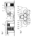
- Fig. 1 shows a schematic view, e.g. B. a sheet-fed rotary printing press in which the printing unit 4 is used, for example.
- the printing press includes one Sheet feeder 1 with a sheet stack 2, of which automatically on one constant level held top sheet individually or scaled by one Belt conveyor 3 of the printing unit 4 are fed, which the sheets individually takes over, printed and outputs to a chain conveyor 6, which in the case of Multi-color printing further printing units in the manner of printing unit 4 or, as shown here feeds a delivery stack 5 directly.
- the sheets pass through the printing unit 4 from top to bottom; its structure is in Fig. 2 in shown on a larger scale.
- Two transport cylinders 7, of which the upper one is only partially shown in the figure, are each provided at a section 8 of their circumference with bow grippers to printing sheets with register to their edge from the first belt conveyor 3 take.
- the lower of the two transport cylinders 7 rolls in contact with a first one Transfer cylinder 9 from.
- the transfer cylinder 9 is, for. B. as a blanket cylinder 9 formed and is also on a portion 11 of its circumference with a Gripper bridge for taking over the sheets from the lower transport cylinder 7 fitted.
- the first blanket cylinder 9 also rolls into contact with a first one Screen printing cylinder 12, whereby a print pattern is transferred to it, which in the gap 13 between the transport cylinder 7 and the first blanket cylinder 9 on one funded sheet is printed.
- On the structure of the first screen printing cylinder 12 is discussed in more detail later.
- one sheet to be printed After passing through the nip 13, one sheet to be printed reaches a second one Gap 14 between the first blanket cylinder 9 and a second, also as Blanket cylinder 16 formed transfer cylinder 16.
- this gap 14 is the sheet on its second side with one of a second screen printing cylinder 17 printed the second blanket cylinder 16 transferred pattern.
- the second blanket cylinder 16 has no gripper bridge; instead, he orders in a section 18 of its circumference over a channel that the passage of the Gripper bridge 11 of the blanket cylinder 9 through the gap 14 allows.
- the various cylinders 7; 9; 16; 12; 17 are in each case on their end faces Side frames 19; 21; 22 stored. These side frames 19; 21; 22 exist at in Fig. 2 shown printing unit each from a central module, which the Transport cylinder 7 and the two blanket cylinders 9; 16 bears, as well as two side Modules, each one of the screen printing cylinders 12; 17 wear.
- the face plates of a module are firmly connected to each other so that they are rigid Form frame unit, which together with the screen printing cylinder 12 or carried by them 17 is removable from the printing unit 4.
- Such a module can then, for. B. by a another module to be replaced, which a form cylinder z. B. for conventional Contains flat offset printing or the like. In this way, the printing unit conveniently adapt to documents where different needs different printing techniques for the front and back are required, register print in one go.
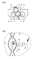
- Fig. 3 shows a simplified modification of the printing unit from Fig. 2.
- the second blanket cylinder 16 has been omitted, instead, the second screen printing cylinder 17 'forms together with the first Blanket cylinder 9 directly the second printing nip 14.
- the first blanket cylinder 9 thus takes over the function of an impression cylinder for the second Screen printing cylinder 17 '.
- the screen printing cylinder 12 has a support ring 20 at its axial ends the outer periphery of a sieve 23, for. B. from silk or polyamide gauze or Bronze wire mesh, is stretched.
- a doctor blade 24 arranged, the position in the radial direction by a curved body, here a on the end faces of the screen printing cylinder 12 formed guide slot 26, controlled through which a cylindrical guide extension 27 of the doctor blade 24 extends.
- the guide extension 27 is on both sides in the direction the axes of rotation of the two cylinders 9; 12 connecting line 28 slidably mounted.
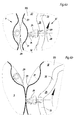
- FIG 4a shows the doctor blade 24 in a position in which the holding device 29 of the Blanket cylinder 9 the gap between the two cylinders 9; 12 passes through.
- the screen 23 has a radially inward indented section 31.
- the guide slot 26 does not have one in the figure fully illustrated, concentric with the cylindrical outer surface of the screen 23 arcuate section 33 and an inwardly indented section 32, the course of which corresponds to section 31.
- section 32 The course of section 32 is chosen so that when section 32 rotates as screen printing cylinder 12 rotates Guide extension 27 moved past, the squeegee 24 withdrawn radially inward as far is that there is only minimal pressure on the screen 23, which does not result in any significant deformation of the screen 23 in section 31, or that it causes contact completely loses with the screen 23 and thus does not exert any pressure on the section 31 thereof, that could deform it and damage it during operation.
- Fig. 4b shows the position of the squeegee 24 after the section 32 the guide extension 27 happened.
- the arcuate section 33 of the guide slot 26 holds the Doctor blade 24 pressed against the inside of the screen 23, so that one on the doctor blade 24 Color 34 is pressed through the open areas of the screen 23 and on is transferred to the blanket cylinder 9 in this way.
- FIG. 5 shows a modification of the screen printing cylinder 12 from FIG. 4a, b. Elements that correspond to those of the screen printing cylinder 12 described above, are the same Reference numerals are used and will not be described again.
- the construction of the Screen printing cylinder 12 from FIG. 5 is due to the omission of the guide slot 26 simplified.
- the doctor blade 24 is against by a spring device (not shown) Sieve 23 held down. The doctor blade 24 thus remains in contact with the screen 23, if the indented during the rotational movement of the screen printing cylinder 12 Section 31 passes the doctor blade 24. At the passage of the indented section 31 in front of the doctor blade 24, the latter against the force of the spring device to the axis of Screen printing cylinder 12 pushed back.
- the support element 36 here has the shape of an Cross-section of continuously curved shell or gutter, e.g. B. from sheet metal or a rigid plastic, and is at its two axial ends on the front sides of the Screen printing cylinder 12 anchored.
- the support element 36 can be adjustable in the radial direction (arrow 37) adjust the tension of the sieve 23.
- the support element 36 each with the holding device 29 of the blanket cylinder 9 meets and thus in the area of section 31, no ink can be taken from the screen printing cylinder 12
- the support element 36 is expediently designed as a closed plate that no ink pass through and get onto the exterior of the screen printing cylinder 12 can.
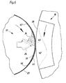
- This screen printing cylinder 17 is cylindrical over its entire circumference, without one indented section. It is therefore suitable with a second cylinder cooperate with no radially outwardly projecting elements such as Has holding devices for a printing material. Based on the printing unit 1, the second screen printing cylinder 17 may have the construction shown in FIG. 6. For this reason, the reference numerals 17 for the screen printing cylinder and 16 used for the cylinder interacting with it.
- a support element 39 is arranged radially inside the sieve 23, which is located in Circumferential direction of the screen printing cylinder 17 over a section 41 of the screen 23 extends, which corresponds to the expansion of the channel 38 on the blanket cylinder 16.
- the Support element 39 is a closed plate which is curved in the form of a cylinder segment made of metal or rigid plastic.
- the support element 39 is attached radially inside the sieve 23, and is leading End 42 and trailing end 43 of the screen 23 overlap each other in the Supporting element 39 supported section 41. In this way, the sensitive Connection between the two ends 42; 43, the z. B. can be welded before Contact with the doctor blade 24 and thus protected against premature wear.
- a spring element for an adjustment of the doctor blade 24 in the radial direction can be provided. Because with this Variant, however, the inner radius of the surface swept by the doctor blade 24, you can further simplify the construction of the screen printing cylinder 17 by clicking adjustability of the doctor blade 24 is dispensed with, so that the fluctuations in the radius alone by an elastic deformation of the elastic lip 44 touching the screen 23 Doctor blade 24 are compensated.
- edges 46; 47; preferably the edges 46; 47 each have a helix with a Pitch that is a multiple of the axial length of the screen printing cylinder 17.
Landscapes
- Engineering & Computer Science (AREA)
- Mechanical Engineering (AREA)
- Screen Printers (AREA)
Applications Claiming Priority (5)
| Application Number | Priority Date | Filing Date | Title |
|---|---|---|---|
| DE10003158 | 2000-01-25 | ||
| DE10003158 | 2000-01-25 | ||
| DE10026000A DE10026000C2 (de) | 2000-01-25 | 2000-05-25 | Siebdruckzylinder |
| DE10026000 | 2000-05-25 | ||
| EP00991089A EP1250231A1 (fr) | 2000-01-25 | 2000-12-16 | Cylindre de serigraphie |
Related Parent Applications (1)
| Application Number | Title | Priority Date | Filing Date |
|---|---|---|---|
| EP00991089A Division EP1250231A1 (fr) | 2000-01-25 | 2000-12-16 | Cylindre de serigraphie |
Publications (1)
| Publication Number | Publication Date |
|---|---|
| EP1440802A2 true EP1440802A2 (fr) | 2004-07-28 |
Family
ID=7628692
Family Applications (1)
| Application Number | Title | Priority Date | Filing Date |
|---|---|---|---|
| EP04101719A Withdrawn EP1440802A2 (fr) | 2000-01-25 | 2000-12-16 | Cylindre de sérigrafie |
Country Status (2)
| Country | Link |
|---|---|
| EP (1) | EP1440802A2 (fr) |
| DE (1) | DE10026000C2 (fr) |
Cited By (3)
| Publication number | Priority date | Publication date | Assignee | Title |
|---|---|---|---|---|
| EP1820646A3 (fr) * | 2006-02-10 | 2010-05-26 | Komori Corporation | Dispositif d'alimentation en liquide |
| EP1717028A3 (fr) * | 2005-04-27 | 2010-10-06 | Komori Corporation | Appareil d'alimentation en liquide |
| CN115583100A (zh) * | 2022-08-18 | 2023-01-10 | 泰兴市中能高科新型材料有限公司 | 一种彩色聚四氟乙烯图案的涂刷方法及其涂刷装置 |
Families Citing this family (2)
| Publication number | Priority date | Publication date | Assignee | Title |
|---|---|---|---|---|
| EP1876021A4 (fr) * | 2005-04-27 | 2009-08-05 | Komori Printing Mach | Dispositif d'alimentation en liquides |
| JP6379020B2 (ja) * | 2014-12-02 | 2018-08-22 | 株式会社セリアコーポレーション | スクリーン印刷機 |
Citations (4)
| Publication number | Priority date | Publication date | Assignee | Title |
|---|---|---|---|---|
| US3155034A (en) | 1961-11-01 | 1964-11-03 | Rineglas Inc | Silk screen printing press |
| DE2040567A1 (de) | 1969-08-15 | 1971-02-25 | Stork Amsterdam | Verfahren und Vorrichtung zum Auftragen einer Substanz auf eine sich fortbewegende Materialbahn |
| US5285724A (en) | 1990-08-31 | 1994-02-15 | Ricoh Company, Ltd. | Ink scraper for a stencil printer |
| EP0723864B1 (fr) | 1995-01-24 | 1998-08-19 | De La Rue Giori S.A. | Machine rotative de sérigraphie pour l'impression de feuilles |
-
2000
- 2000-05-25 DE DE10026000A patent/DE10026000C2/de not_active Expired - Fee Related
- 2000-12-16 EP EP04101719A patent/EP1440802A2/fr not_active Withdrawn
Patent Citations (4)
| Publication number | Priority date | Publication date | Assignee | Title |
|---|---|---|---|---|
| US3155034A (en) | 1961-11-01 | 1964-11-03 | Rineglas Inc | Silk screen printing press |
| DE2040567A1 (de) | 1969-08-15 | 1971-02-25 | Stork Amsterdam | Verfahren und Vorrichtung zum Auftragen einer Substanz auf eine sich fortbewegende Materialbahn |
| US5285724A (en) | 1990-08-31 | 1994-02-15 | Ricoh Company, Ltd. | Ink scraper for a stencil printer |
| EP0723864B1 (fr) | 1995-01-24 | 1998-08-19 | De La Rue Giori S.A. | Machine rotative de sérigraphie pour l'impression de feuilles |
Cited By (3)
| Publication number | Priority date | Publication date | Assignee | Title |
|---|---|---|---|---|
| EP1717028A3 (fr) * | 2005-04-27 | 2010-10-06 | Komori Corporation | Appareil d'alimentation en liquide |
| EP1820646A3 (fr) * | 2006-02-10 | 2010-05-26 | Komori Corporation | Dispositif d'alimentation en liquide |
| CN115583100A (zh) * | 2022-08-18 | 2023-01-10 | 泰兴市中能高科新型材料有限公司 | 一种彩色聚四氟乙烯图案的涂刷方法及其涂刷装置 |
Also Published As
| Publication number | Publication date |
|---|---|
| DE10026000A1 (de) | 2001-08-02 |
| DE10026000C2 (de) | 2002-04-11 |
Similar Documents
| Publication | Publication Date | Title |
|---|---|---|
| EP0883493B1 (fr) | Cylindre d'impression d'une machine a feuilles | |
| EP0723864B1 (fr) | Machine rotative de sérigraphie pour l'impression de feuilles | |
| EP1250226B1 (fr) | Presse pour impression en creux | |
| EP0936065B1 (fr) | Dispositif pour appliquer un liquide sur une feuille imprimé, notamment unité d'impression ou de lacquage dans une machine rotative d'impression pour feuilles | |
| EP1250228B1 (fr) | Unite imprimante | |
| EP1250230B1 (fr) | Machine a imprimer sur feuilles dotee d'un cylindre serigraphique | |
| DE10026000C2 (de) | Siebdruckzylinder | |
| EP1515848B1 (fr) | Paire de cylindres et cylindre d'un groupe d'impression d'une presse rotative offset | |
| DE3409479A1 (de) | Spannvorrichtungen fuer an deren in bogenlaufrichtung vorderen und hinteren kanten gelochte druckplatten fuer offsetdruckmaschinen | |
| DE69124383T2 (de) | Offsetdruckmaschine | |
| EP0467832B1 (fr) | Dispositif pour le transfert des feuilles seules au cylindre presseur d'une presse rotative à feuilles | |
| DE2724856A1 (de) | Bogenbrotationsdruckmaschine | |
| DE2411691C3 (de) | Kombinierte Mehrfarben-Offset- und Stichdruckrotationsmaschine | |
| EP1250231A1 (fr) | Cylindre de serigraphie | |
| DE10035354B4 (de) | Offsetdruckmaschine | |
| EP1250229B1 (fr) | Unite d'impression | |
| DE10025995C1 (de) | Druckeinheit mit zwei Siebdruckzylindern | |
| EP1515851B1 (fr) | Cylindre d'un groupe d'impression d'une presse rotative | |
| DE10025999A1 (de) | Druckeinheit | |
| DE2314302B2 (de) | Verfahren und einrichtung zum erzielen eines einwandfreien druckes in einem doppeldruckwerk einer mehrfarben- bogenrotations-offsetdruckmaschine | |
| DE10025994C1 (de) | Druckeinheit | |
| EP0455782A1 (fr) | Imprimante offset rotative a feuilles | |
| DE102016203635B4 (de) | Verfahren zum Betreiben einer Druckmaschine | |
| DE4340867A1 (de) | Einrichtung zum An- und Abstellen einer Kammerrakel an eine Auftragwalze in Rotationsdruckmaschinen | |
| DE102016215761B4 (de) | Zylinder für eine Bogen verarbeitende Maschine |
Legal Events
| Date | Code | Title | Description |
|---|---|---|---|
| PUAI | Public reference made under article 153(3) epc to a published international application that has entered the european phase |
Free format text: ORIGINAL CODE: 0009012 |
|
| AC | Divisional application: reference to earlier application |
Ref document number: 1250231 Country of ref document: EP Kind code of ref document: P |
|
| AK | Designated contracting states |
Kind code of ref document: A2 Designated state(s): AT BE CH CY DE DK ES FI FR GB GR IE IT LI LU MC NL PT SE TR |
|
| STAA | Information on the status of an ep patent application or granted ep patent |
Free format text: STATUS: THE APPLICATION HAS BEEN WITHDRAWN |
|
| 18W | Application withdrawn |
Effective date: 20050425 |