EP1440802A2 - Screen cylinder - Google Patents
Screen cylinder Download PDFInfo
- Publication number
- EP1440802A2 EP1440802A2 EP04101719A EP04101719A EP1440802A2 EP 1440802 A2 EP1440802 A2 EP 1440802A2 EP 04101719 A EP04101719 A EP 04101719A EP 04101719 A EP04101719 A EP 04101719A EP 1440802 A2 EP1440802 A2 EP 1440802A2
- Authority
- EP
- European Patent Office
- Prior art keywords
- cylinder
- screen
- screen printing
- printing cylinder
- section
- Prior art date
- Legal status (The legal status is an assumption and is not a legal conclusion. Google has not performed a legal analysis and makes no representation as to the accuracy of the status listed.)
- Withdrawn
Links
- 238000007650 screen-printing Methods 0.000 claims description 70
- 238000007639 printing Methods 0.000 claims description 38
- 230000002093 peripheral effect Effects 0.000 claims description 3
- 238000010276 construction Methods 0.000 description 5
- 238000012986 modification Methods 0.000 description 4
- 230000004048 modification Effects 0.000 description 4
- 239000000463 material Substances 0.000 description 2
- 239000002184 metal Substances 0.000 description 2
- 239000004033 plastic Substances 0.000 description 2
- 229910000906 Bronze Inorganic materials 0.000 description 1
- 239000004952 Polyamide Substances 0.000 description 1
- 230000004323 axial length Effects 0.000 description 1
- 239000010974 bronze Substances 0.000 description 1
- 230000000295 complement effect Effects 0.000 description 1
- KUNSUQLRTQLHQQ-UHFFFAOYSA-N copper tin Chemical compound [Cu].[Sn] KUNSUQLRTQLHQQ-UHFFFAOYSA-N 0.000 description 1
- 230000000694 effects Effects 0.000 description 1
- 230000005489 elastic deformation Effects 0.000 description 1
- 238000000034 method Methods 0.000 description 1
- 238000007645 offset printing Methods 0.000 description 1
- 239000003973 paint Substances 0.000 description 1
- 235000011837 pasties Nutrition 0.000 description 1
- 229920002647 polyamide Polymers 0.000 description 1
- 230000002028 premature Effects 0.000 description 1
- 230000003014 reinforcing effect Effects 0.000 description 1
- 230000007704 transition Effects 0.000 description 1
Images
Classifications
-
- B—PERFORMING OPERATIONS; TRANSPORTING
- B41—PRINTING; LINING MACHINES; TYPEWRITERS; STAMPS
- B41F—PRINTING MACHINES OR PRESSES
- B41F15/00—Screen printers
- B41F15/14—Details
- B41F15/34—Screens, Frames; Holders therefor
- B41F15/38—Screens, Frames; Holders therefor curved
-
- B—PERFORMING OPERATIONS; TRANSPORTING
- B41—PRINTING; LINING MACHINES; TYPEWRITERS; STAMPS
- B41F—PRINTING MACHINES OR PRESSES
- B41F15/00—Screen printers
- B41F15/08—Machines
- B41F15/0804—Machines for printing sheets
- B41F15/0809—Machines for printing sheets with cylindrical or belt-like screens
Definitions
- the invention relates to a screen printing cylinder of a printing unit according to the preamble of claim 1.
- a printing unit for a rotary printing press is known from EP 07 23 864 B1, which a screen printing cylinder and a printing nip formed by two cylinders, in which a printing material is printed.
- a screen printing cylinder of this printing unit forms a printing nip together with one Impression cylinder, which has circumferential sections with a reduced radius, in which Bow grippers are arranged.
- a squeegee device is located inside the screen printing cylinder arranged towards the printing nip, against the screen of the screen printing cylinder presses and passes paint through. To avoid deformation of the screen, if a circumferential section with a reduced radius passes through the printing nip is one Mechanism provided that moves the squeegee device from the screen at these times.
- This known printing unit is only suitable for single-sided printing.
- the mechanism to move the squeegee device is expensive.
- US 52 85 724 A discloses a screen printing cylinder with a screen, the end of which is provided with a reinforcing part.
- US 31 55 034 A discloses a screen printing machine for sheet printing, in which the Holding device for the screen is arranged in the channel of an impression cylinder.
- DE 20 40 567 A shows a screen printing machine in which one in the impression cylinder Back-up roller for the doctor blade of an associated screen printing cylinder is arranged.
- the invention has for its object to provide a screen printing cylinder.
- a device for preventing deformation of the screen is advantageous the squeegee device pressing against it on a defined circumferential section of the Siebes provided. This device prevents the sieve from being pressed against it the holding device or a pushing into one of the holding device complementary channel of the other cylinder forming the pressure gap too strong deformed and thereby worn or damaged too quickly.
- the device is a support element, which is located on the screen printing cylinder in the area of Set circumferential portion extends axially and to intercept one of the Doctor device radially outwardly exerted pressure on the specified Perimeter section serves.
- the doctor device is preferably with Provide leading and trailing edges for the doctor device, which are at an angle to one Generating the peripheral surface of the screen cylinder. Because the doctor device necessarily runs parallel to such a generator, it runs Squeegee device in each case not on its entire extent, but only selectively the support element on or from this, and possibly thereby on the Braking forces acting on screen printing cylinders remain small and are spread over one finite section of the circumference of the screen printing cylinder.
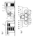
- Fig. 1 shows a schematic view, e.g. B. a sheet-fed rotary printing press in which the printing unit 4 is used, for example.
- the printing press includes one Sheet feeder 1 with a sheet stack 2, of which automatically on one constant level held top sheet individually or scaled by one Belt conveyor 3 of the printing unit 4 are fed, which the sheets individually takes over, printed and outputs to a chain conveyor 6, which in the case of Multi-color printing further printing units in the manner of printing unit 4 or, as shown here feeds a delivery stack 5 directly.
- the sheets pass through the printing unit 4 from top to bottom; its structure is in Fig. 2 in shown on a larger scale.
- Two transport cylinders 7, of which the upper one is only partially shown in the figure, are each provided at a section 8 of their circumference with bow grippers to printing sheets with register to their edge from the first belt conveyor 3 take.
- the lower of the two transport cylinders 7 rolls in contact with a first one Transfer cylinder 9 from.
- the transfer cylinder 9 is, for. B. as a blanket cylinder 9 formed and is also on a portion 11 of its circumference with a Gripper bridge for taking over the sheets from the lower transport cylinder 7 fitted.
- the first blanket cylinder 9 also rolls into contact with a first one Screen printing cylinder 12, whereby a print pattern is transferred to it, which in the gap 13 between the transport cylinder 7 and the first blanket cylinder 9 on one funded sheet is printed.
- On the structure of the first screen printing cylinder 12 is discussed in more detail later.
- one sheet to be printed After passing through the nip 13, one sheet to be printed reaches a second one Gap 14 between the first blanket cylinder 9 and a second, also as Blanket cylinder 16 formed transfer cylinder 16.
- this gap 14 is the sheet on its second side with one of a second screen printing cylinder 17 printed the second blanket cylinder 16 transferred pattern.
- the second blanket cylinder 16 has no gripper bridge; instead, he orders in a section 18 of its circumference over a channel that the passage of the Gripper bridge 11 of the blanket cylinder 9 through the gap 14 allows.
- the various cylinders 7; 9; 16; 12; 17 are in each case on their end faces Side frames 19; 21; 22 stored. These side frames 19; 21; 22 exist at in Fig. 2 shown printing unit each from a central module, which the Transport cylinder 7 and the two blanket cylinders 9; 16 bears, as well as two side Modules, each one of the screen printing cylinders 12; 17 wear.
- the face plates of a module are firmly connected to each other so that they are rigid Form frame unit, which together with the screen printing cylinder 12 or carried by them 17 is removable from the printing unit 4.
- Such a module can then, for. B. by a another module to be replaced, which a form cylinder z. B. for conventional Contains flat offset printing or the like. In this way, the printing unit conveniently adapt to documents where different needs different printing techniques for the front and back are required, register print in one go.
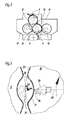
- Fig. 3 shows a simplified modification of the printing unit from Fig. 2.
- the second blanket cylinder 16 has been omitted, instead, the second screen printing cylinder 17 'forms together with the first Blanket cylinder 9 directly the second printing nip 14.
- the first blanket cylinder 9 thus takes over the function of an impression cylinder for the second Screen printing cylinder 17 '.
- the screen printing cylinder 12 has a support ring 20 at its axial ends the outer periphery of a sieve 23, for. B. from silk or polyamide gauze or Bronze wire mesh, is stretched.
- a doctor blade 24 arranged, the position in the radial direction by a curved body, here a on the end faces of the screen printing cylinder 12 formed guide slot 26, controlled through which a cylindrical guide extension 27 of the doctor blade 24 extends.
- the guide extension 27 is on both sides in the direction the axes of rotation of the two cylinders 9; 12 connecting line 28 slidably mounted.
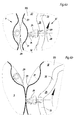
- FIG 4a shows the doctor blade 24 in a position in which the holding device 29 of the Blanket cylinder 9 the gap between the two cylinders 9; 12 passes through.
- the screen 23 has a radially inward indented section 31.
- the guide slot 26 does not have one in the figure fully illustrated, concentric with the cylindrical outer surface of the screen 23 arcuate section 33 and an inwardly indented section 32, the course of which corresponds to section 31.
- section 32 The course of section 32 is chosen so that when section 32 rotates as screen printing cylinder 12 rotates Guide extension 27 moved past, the squeegee 24 withdrawn radially inward as far is that there is only minimal pressure on the screen 23, which does not result in any significant deformation of the screen 23 in section 31, or that it causes contact completely loses with the screen 23 and thus does not exert any pressure on the section 31 thereof, that could deform it and damage it during operation.
- Fig. 4b shows the position of the squeegee 24 after the section 32 the guide extension 27 happened.
- the arcuate section 33 of the guide slot 26 holds the Doctor blade 24 pressed against the inside of the screen 23, so that one on the doctor blade 24 Color 34 is pressed through the open areas of the screen 23 and on is transferred to the blanket cylinder 9 in this way.
- FIG. 5 shows a modification of the screen printing cylinder 12 from FIG. 4a, b. Elements that correspond to those of the screen printing cylinder 12 described above, are the same Reference numerals are used and will not be described again.
- the construction of the Screen printing cylinder 12 from FIG. 5 is due to the omission of the guide slot 26 simplified.
- the doctor blade 24 is against by a spring device (not shown) Sieve 23 held down. The doctor blade 24 thus remains in contact with the screen 23, if the indented during the rotational movement of the screen printing cylinder 12 Section 31 passes the doctor blade 24. At the passage of the indented section 31 in front of the doctor blade 24, the latter against the force of the spring device to the axis of Screen printing cylinder 12 pushed back.
- the support element 36 here has the shape of an Cross-section of continuously curved shell or gutter, e.g. B. from sheet metal or a rigid plastic, and is at its two axial ends on the front sides of the Screen printing cylinder 12 anchored.
- the support element 36 can be adjustable in the radial direction (arrow 37) adjust the tension of the sieve 23.
- the support element 36 each with the holding device 29 of the blanket cylinder 9 meets and thus in the area of section 31, no ink can be taken from the screen printing cylinder 12
- the support element 36 is expediently designed as a closed plate that no ink pass through and get onto the exterior of the screen printing cylinder 12 can.
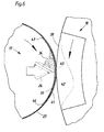
- This screen printing cylinder 17 is cylindrical over its entire circumference, without one indented section. It is therefore suitable with a second cylinder cooperate with no radially outwardly projecting elements such as Has holding devices for a printing material. Based on the printing unit 1, the second screen printing cylinder 17 may have the construction shown in FIG. 6. For this reason, the reference numerals 17 for the screen printing cylinder and 16 used for the cylinder interacting with it.
- a support element 39 is arranged radially inside the sieve 23, which is located in Circumferential direction of the screen printing cylinder 17 over a section 41 of the screen 23 extends, which corresponds to the expansion of the channel 38 on the blanket cylinder 16.
- the Support element 39 is a closed plate which is curved in the form of a cylinder segment made of metal or rigid plastic.
- the support element 39 is attached radially inside the sieve 23, and is leading End 42 and trailing end 43 of the screen 23 overlap each other in the Supporting element 39 supported section 41. In this way, the sensitive Connection between the two ends 42; 43, the z. B. can be welded before Contact with the doctor blade 24 and thus protected against premature wear.
- a spring element for an adjustment of the doctor blade 24 in the radial direction can be provided. Because with this Variant, however, the inner radius of the surface swept by the doctor blade 24, you can further simplify the construction of the screen printing cylinder 17 by clicking adjustability of the doctor blade 24 is dispensed with, so that the fluctuations in the radius alone by an elastic deformation of the elastic lip 44 touching the screen 23 Doctor blade 24 are compensated.
- edges 46; 47; preferably the edges 46; 47 each have a helix with a Pitch that is a multiple of the axial length of the screen printing cylinder 17.
Landscapes
- Engineering & Computer Science (AREA)
- Mechanical Engineering (AREA)
- Screen Printers (AREA)
Abstract
Description
Die Erfindung betrifft einen Siebdruckzylinder einer Druckeinheit gemäß dem Oberbegriff des Anspruches 1.The invention relates to a screen printing cylinder of a printing unit according to the preamble of claim 1.
Aus der EP 07 23 864 B1 ist eine Druckeinheit für eine Rotationsdruckmaschine bekannt, die einen Siebdruckzylinder und einen von zwei Zylindern gebildeten Druckspalt, in dem ein Bedruckstoff bedruckt wird, aufweist.A printing unit for a rotary printing press is known from EP 07 23 864 B1, which a screen printing cylinder and a printing nip formed by two cylinders, in which a printing material is printed.
Ein Siebdruckzylinder dieser Druckeinheit bildet einen Druckspalt zusammen mit einem Gegendruckzylinder, der Umfangsabschnitte mit verringertem Radius aufweist, in denen Bogengreifer angeordnet sind. Im Innern des Siebdruckzylinders ist eine Rakeleinrichtung dem Druckspalt zugewandt angeordnet, die gegen das Sieb des Siebdruckzylinders drückt und Farbe hindurchstreicht. Um eine Verformung des Siebes zu vermeiden, wenn ein Umfangsabschnitt mit verringertem Radius den Druckspalt durchläuft, ist ein Mechanismus vorgesehen, der zu diesen Zeiten die Rakeleinrichtung vom Sieb abrückt.A screen printing cylinder of this printing unit forms a printing nip together with one Impression cylinder, which has circumferential sections with a reduced radius, in which Bow grippers are arranged. A squeegee device is located inside the screen printing cylinder arranged towards the printing nip, against the screen of the screen printing cylinder presses and passes paint through. To avoid deformation of the screen, if a circumferential section with a reduced radius passes through the printing nip is one Mechanism provided that moves the squeegee device from the screen at these times.
Diese bekannte Druckeinheit ist nur zum einseitigen Drucken geeignet. Der Mechanismus zum Abrücken der Rakeleinrichtung ist aufwendig.This known printing unit is only suitable for single-sided printing. The mechanism to move the squeegee device is expensive.
Die US 52 85 724 A offenbart einen Siebdruckzylinder mit einem Sieb, dessen Ende mit einem Verstärkungsteil versehen ist.US 52 85 724 A discloses a screen printing cylinder with a screen, the end of which is provided with a reinforcing part.
Die US 31 55 034 A offenbart eine Siebdruckmaschine für Bogendruck, bei der die Halteeinrichtung für das Sieb im Kanal eines Gegendruckzylinders angeordnet ist.US 31 55 034 A discloses a screen printing machine for sheet printing, in which the Holding device for the screen is arranged in the channel of an impression cylinder.
Die DE 20 40 567 A zeigt eine Siebdruckmaschine, bei der im Gegendruckzylinder eine Stützwalze für die Rakel eines zugeordneten Siebdruckzylinders angeordnet ist.DE 20 40 567 A shows a screen printing machine in which one in the impression cylinder Back-up roller for the doctor blade of an associated screen printing cylinder is arranged.
Der Erfindung liegt die Aufgabe zugrunde, einen Siebdruckzylinder zu schaffen.The invention has for its object to provide a screen printing cylinder.
Die Aufgabe wird erfindungsgemäß durch die Merkmale des Anspruches 1 gelöst.The object is achieved by the features of claim 1.
Vorteilhafterweise ist eine Einrichtung zum Verhindern einer Verformung des Siebs durch die dagegen drückende Rakeleinrichtung auf einem festgelegten Umfangsabschnitt des Siebes vorgesehen. Diese Einrichtung verhindert, dass das Sieb durch ein Andrücken an die Halteeinrichtung oder ein Hineindrücken in einen zu der Halteeinrichtung komplementären Kanal des jeweils anderen den Druckspalt bildenden Zylinders zu stark verformt und dadurch zu schnell abgenutzt oder beschädigt wird.A device for preventing deformation of the screen is advantageous the squeegee device pressing against it on a defined circumferential section of the Siebes provided. This device prevents the sieve from being pressed against it the holding device or a pushing into one of the holding device complementary channel of the other cylinder forming the pressure gap too strong deformed and thereby worn or damaged too quickly.
Die Einrichtung ist ein Stützelement, das sich am Siebdruckzylinder im Bereich des festgelegten Umfangsabschnitts axial erstreckt und zum Abfangen eines von der Rakeleinrichtung radial nach außen ausgeübten Drucks auf den festgelegten Umfangsabschnitt dient.The device is a support element, which is located on the screen printing cylinder in the area of Set circumferential portion extends axially and to intercept one of the Doctor device radially outwardly exerted pressure on the specified Perimeter section serves.
Um Gleichlaufstörungen des Siebdruckzylinders zu vermeiden, wenn die Rakeleinrichtung auf das Stützelement trifft und/oder sich von diesem trennt, ist letzteres vorzugsweise mit Auf- und Ablaufkanten für die Rakeleinrichtung versehen, die unter einem Winkel zu einer Erzeugenden der Umfangsfläche des Siebzylinders verlaufen. Da die Rakeleinrichtung notwendigerweise parallel zu einer solchen Erzeugenden verläuft, läuft die Rakeleinrichtung jeweils nicht auf ihrer gesamten Ausdehnung, sondern nur punktuell auf das Stützelement auf oder von diesem ab, und eventuell dadurch auf den Siebdruckzylinder wirkende Bremskräfte bleiben klein und verteilen sich auf einen endlichen Abschnitt des Umfangs des Siebdruckzylinders.To avoid synchronism of the screen printing cylinder when the doctor device meets and / or separates from the support element, the latter is preferably with Provide leading and trailing edges for the doctor device, which are at an angle to one Generating the peripheral surface of the screen cylinder. Because the doctor device necessarily runs parallel to such a generator, it runs Squeegee device in each case not on its entire extent, but only selectively the support element on or from this, and possibly thereby on the Braking forces acting on screen printing cylinders remain small and are spread over one finite section of the circumference of the screen printing cylinder.
Ausführungsbeispiele der Erfindung sind in den Zeichnungen dargestellt und werden im folgenden näher beschrieben.Embodiments of the invention are shown in the drawings and are in following described in more detail.
Es zeigen:
- Fig. 1
- eine schematische Darstellung einer Druckmaschine mit einer Druckeinheit;
- Fig. 2
- die Druckeinheit der Maschine aus Fig. 1 in einem schematischen Schnitt;
- Fig. 3
- eine Druckeinheit gemäß einer zweiten Ausgestaltung der Erfindung in einem schematischen Schnitt;
- Fig. 4a und Fig. 4b
- jeweils einen Ausschnitt eines Siebdruckzylinders und eines mit diesem zusammenwirkenden Übertragungszylinders in zwei Phasen der Drehbewegung der Zylinder;
- Fig. 5
- eine Abwandlung des Siebdruckzylinders aus Fig. 4a;
- Fig. 6
- einen Ausschnitt eines Siebdruckzylinders und eines Übertragungszylinders gemäß einer abgewandelten Ausgestaltung.
- Fig. 1
- a schematic representation of a printing press with a printing unit;
- Fig. 2
- the printing unit of the machine of Figure 1 in a schematic section.
- Fig. 3
- a printing unit according to a second embodiment of the invention in a schematic section;
- 4a and 4b
- in each case a section of a screen printing cylinder and a transfer cylinder interacting with it in two phases of the rotary movement of the cylinders;
- Fig. 5
- a modification of the screen printing cylinder from Fig. 4a;
- Fig. 6
- a section of a screen printing cylinder and a transfer cylinder according to a modified embodiment.
Fig. 1 zeigt eine schematische Ansicht, z. B. einer Bogenrotationsdruckmaschine, in der
die Druckeinheit 4 beispielsweise eingesetzt ist. Die Druckmaschine umfasst einen
Bogenanleger 1 mit einem Bogenstapel 2, von dessen automatisch auf einem
gleichbleibenden Niveau gehaltener Oberseite Bogen einzeln oder geschuppt von einem
Bandförderer 3 der Druckeinheit 4 zugeführt werden, welche die Bögen einzeln
übernimmt, bedruckt und an einen Kettenförderer 6 ausgibt, der diese im Fall von
Mehrfarbdruck weiteren Druckeinheiten in Art der Druckeinheit 4 oder, wie hier gezeigt,
direkt einem Auslagestapel 5 zuführt.Fig. 1 shows a schematic view, e.g. B. a sheet-fed rotary printing press in which
the
Die Bogen durchlaufen die Druckeinheit 4 von oben nach unten; ihr Aufbau ist in Fig. 2 in
größerem Maßstab dargestellt.The sheets pass through the
Zwei Transportzylinder 7, von denen die obere in der Figur nur teilweise dargestellt ist,
sind jeweils an einem Abschnitt 8 ihres Umfangs mit Bogengreifern versehen, um zu
bedruckende Bogen passerhaltig zu deren Rand von dem ersten Bandförderer 3 zu
übernehmen. Der untere der zwei Transportzylinder 7 rollt in Kontakt mit einem ersten
Übertragungszylinder 9 ab. Der Übertragungszylinder 9 ist, z. B. als Gummituchzylinder 9
ausgebildet und ist ebenfalls an einem Abschnitt 11 seines Umfangs mit einer
Greiferbrücke zum Übernehmen der Bogen von dem unteren Transportzylinder 7
ausgestattet. Der erste Gummituchzylinder 9 rollt ferner in Kontakt mit einem ersten
Siebdruckzylinder 12 ab, wodurch auf ihn ein Druckmuster übertragen wird, welches in
dem Spalt 13 zwischen Transportzylinder 7 und erstem Gummituchzylinder 9 auf einen
geförderten Bogen gedruckt wird. Auf den Aufbau des ersten Siebdruckzylinders 12 wird
später noch genauer eingegangen.Two
Nach Durchgang durch den Spalt 13 erreicht ein zu bedruckender Bogen einen zweiten
Spalt 14 zwischen dem ersten Gummituchzylinder 9 und einem zweiten, ebenfalls als
Gummituchzylinder 16 ausgebildeten Übertragungszylinder 16. In diesem Spalt 14 wird
der Bogen auf seiner zweiten Seite mit einem von einem zweiten Siebdruckzylinder 17 auf
den zweiten Gummituchzylinder 16 übertragenen Muster bedruckt.After passing through the
Der zweite Gummituchzylinder 16 besitzt keine Greiferbrücke; stattdessen verfügt er in
einem Abschnitt 18 seines Umfangs über einen Kanal, der den Durchgang der
Greiferbrücke 11 des Gummituchzylinders 9 durch den Spalt 14 ermöglicht.The
Da die zwei Gummituchzylinder 9; 16 und mit ihnen auch die Siebdruckzylinder 12; 17
gekoppelt rotieren können, ist es durch eine manuelle oder automatische Feineinstellung
der auf den Siebdruckzylindern 12; 17 montierten Druckformen relativ zu einander in
axialer Richtung und in Umfangsrichtung der Zylinder 9; 16; 12; 17 auf einfache Weise
möglich, eine exakte und dauerhafte Passerhaltigkeit des Drucks auf Vorder- und
Rückseite der Bögen zu erreichen.Since the two
Die diversen oben erwähnten Zylinder 7; 9; 16; 12; 17 sind jeweils an ihren Stirnseiten in
Seitengestellen 19; 21; 22 gelagert. Diese Seitengestelle 19; 21; 22 bestehen bei der in
Fig. 2 gezeigten Druckeinheit jeweils aus einem zentralen Modul, welches die
Transportzylinder 7 und die zwei Gummituchzylinder 9; 16 trägt, sowie zwei seitliche
Modulen, die jeweils einen der Siebdruckzylinder 12; 17 tragen. Die stirnseitigen Platten
eines Moduls sind jeweils fest miteinander verbunden, so dass sie eine starre
Rahmeneinheit bilden, die mitsamt dem von ihnen getragenen Siebdruckzylinder 12 bzw.
17 von der Druckeinheit 4 abnehmbar ist. Ein solches Modul kann dann z. B. durch ein
anderes Modul ersetzt werden, welches einen Formzylinder z. B. für herkömmlichen
Flach-Offsetdruck oder dergleichen enthält. Auf diese Weise lässt sich die Druckeinheit
bequem unterschiedlichen Bedürfnissen anpassen, um Dokumente, bei denen
unterschiedliche Drucktechniken für Vorder- und Rückseite verlangt werden, passerhaltig
in einem Durchgang zu drucken.The
Fig. 3 zeigt eine vereinfachte Abwandlung der Druckeinheit aus Fig. 2. Bei dieser
Abwandlung sind Elemente, die denen der Druckeinheit aus Fig. 2 entsprechen, mit
gleichen Bezugszeichen bezeichnet. Der zweite Gummituchzylinder 16 ist entfallen,
stattdessen bildet der zweite Siebdruckzylinder 17' zusammen mit dem ersten
Gummituchzylinder 9 direkt den zweiten Druckspalt 14. Der erste Gummituchzylinder 9
übernimmt somit die Funktion eines Gegendruckzylinders für den zweiten
Siebdruckzylinder 17'.Fig. 3 shows a simplified modification of the printing unit from Fig. 2. In this
Modification are elements which correspond to those of the printing unit from FIG. 2 with
the same reference numerals. The
Beispiele für den Aufbau der Siebdruckzylinder werden nachfolgend mit Bezug auf die Fig. 4a, 4b sowie 5 beschrieben.Examples of the structure of the screen printing cylinder are given below with reference to the 4a, 4b and 5 described.
Die Fig. 4a, 4b zeigen jeweils einen Teilbereich des ersten Siebdruckzylinders 12 in der
Umgebung des Spalts, den dieser mit dem ersten Gummituchzylinder 9 bildet. Die hier
beschriebenen Strukturen sind allerdings auch in gleicher Weise für den Aufbau des
zweiten Siebdruckzylinders 17 brauchbar. 4a, 4b each show a portion of the first
Der Siebdruckzylinder 12 besitzt jeweils an seinen axialen Enden einen Stützring 20, auf
dessen Außenumfang ein Sieb 23, z. B. aus Seiden- oder Polyamidgaze oder
Bronzedrahtgeflecht, aufgespannt ist. Im Innern des Siebdruckzylinders 12 ist eine Rakel
24 angeordnet, deren Position in radialer Richtung durch einen Kurvenkörper, hier einen
an den Stirnseiten des Siebdruckzylinders 12 ausgebildeten Führungsschlitz 26, gesteuert
ist, durch den ein zylindrischer Führungsfortsatz 27 der Rakel 24 hindurchgreift.
Außerhalb des Siebdruckzylinders 12 ist der Führungsfortsatz 27 beiderseits in Richtung
der die Drehachsen der zwei Zylinder 9; 12 verbindenden Linie 28 verschiebbar gelagert.
Fig. 4a zeigt die Rakel 24 in einer Stellung, in der die Halteeinrichtung 29 des
Gummituchzylinders 9 den Spalt zwischen den zwei Zylindern 9; 12 durchläuft.
Gegenüber der Halteeinrichtung 29 weist das Sieb 23 einen radial nach innen
eingebuchteten Abschnitt 31 auf. Der Führungsschlitz 26 weist einen in der Figur nicht
vollständig dargestellten, zur zylindrischen Außenfläche des Siebes 23 konzentrischen
kreisbogenförmigen Abschnitt 33 und einen nach innen eingebuchteten Abschnitt 32 auf,
dessen Verlauf dem Abschnitt 31 entspricht. Der Verlauf des Abschnitts 32 ist so gewählt,
dass, wenn sich der Abschnitt 32 bei der Rotation des Siebdruckzylinders 12 am
Führungsfortsatz 27 vorbeibewegt, die Rakel 24 so weit radial nach innen zurückgezogen
wird, dass es nur noch einen minimalen Druck auf das Sieb 23 ausübt, der zu keiner
nennenswerten Verformung des Siebs 23 im Abschnitt 31 führt, oder dass es den Kontakt
mit dem Sieb 23 gänzlich verliert und somit keinen Druck auf dessen Abschnitt 31 ausübt,
der diesen verformen und im Laufe des Betriebs beschädigen könnte.The
Fig. 4b zeigt die Stellung der Rakel 24, nachdem der Abschnitt 32 den Führungsfortsatz
27 passiert hat. Der kreisbogenförmige Abschnitt 33 des Führungsschlitzes 26 hält die
Rakel 24 gegen die Innenseite des Siebes 23 gedrückt, so dass eine auf der Rakel 24
befindliche Farbe 34 durch die offenen Bereiche des Siebes 23 hindurchgedrückt und auf
diese Weise auf den Gummituchzylinder 9 übertragen wird.Fig. 4b shows the position of the
Fig. 5 zeigt eine Abwandlung des Siebdruckzylinders 12 aus Fig. 4a, b. Elemente, die
denen des oben beschriebenen Siebdruckzylinders 12 entsprechen, sind mit gleichen
Bezugszeichen bezeichnet und werden nicht erneut beschrieben. Die Konstruktion des
Siebdruckzylinders 12 aus Fig. 5 ist durch den Fortfall des Führungsschlitzes 26
vereinfacht. Die Rakel 24 wird durch eine (nicht dargestellte) Federeinrichtung gegen das
Sieb 23 gedrückt gehalten. Die Rakel 24 bleibt somit auch dann in Kontakt mit dem Sieb
23, wenn sich im Laufe der Drehbewegung des Siebdruckzylinders 12 der eingebuchtete
Abschnitt 31 die Rakel 24 passiert. Bei der Passage des eingebuchteten Abschnitts 31
vor der Rakel 24 wird letzteres entgegen der Kraft der Federeinrichtung zur Achse des
Siebdruckzylinders 12 hin zurückgedrängt. Um dabei eine Verformung des Siebes 23 in
dem Abschnitt 31 durch die Rakel 24 zu vermeiden, ist das Sieb 23 an seiner Außenseite
durch ein Stützelement 36 abgestützt. Das Stützelement 36 hat hier die Form einer im
Querschnitt kontinuierlich gewölbten Schale oder Rinne, z. B. aus Blech oder einem
steifen Kunststoff, und ist an seinen beiden axialen Enden an den Stirnseiten des
Siebdruckzylinders 12 verankert. Vorteilhafterweise befinden sich auch führendes und
nacheilendes Ende des Siebes 23 in dem von dem Stützelement 36 überdeckten
Abschnitt 31. Das Stützelement 36 kann in radialer Richtung (Pfeil 37) justierbar sein, um
die Spannung des Siebes 23 einzustellen.FIG. 5 shows a modification of the
Da bei der Drehung der Zylinder 9; 12 der Druckeinheit das Stützelement 36 jeweils mit
der Halteeinrichtung 29 des Gummituchzylinders 9 zusammentrifft und somit im Bereich
des Abschnitt 31 keine Farbe vom Siebdruckzylinder 12 abgenommen werden kann, ist
das Stützelement 36 zweckmäßigerweise als eine geschlossene Platte ausgebildet, durch
die keine Farbe hindurchtreten und auf das Äußere des Siebdruckzylinders 12 gelangen
kann.Since when the
Fig. 6 zeigt anhand eines Ausschnitts einen alternativen Aufbau eines Siebdruckzylinders 17.6 shows an alternative construction of a screen printing cylinder on the basis of a detail 17th
Dieser Siebdruckzylinder 17 ist auf seinem gesamten Umfang zylindrisch, ohne einen
eingebuchteten Abschnitt. Er ist daher geeignet, mit einem zweiten Zylinder
zusammenzuwirken, der keine radial nach außen vorstehenden Elemente wie etwa
Haltevorrichtungen für einen Bedruckstoff aufweist. Bezogen auf die Druckeinheit aus
Fig. 1 kann der zweite Siebdruckzylinder 17 die in Fig. 6 gezeigte Konstruktion aufweisen.
Deshalb werden im Folgenden die Bezugszeichen 17 für den Siebdruckzylinder und 16
für den mit ihm zusammenwirkenden Zylinder verwendet.This
Wie im Fall der Siebdruckzylinders aus Fig. 4a, b und 5 ist im Innern des hier gezeigten
Siebdruckzylinders 17 eine Rakel 24 angeordnet, das eine pastenartige Farbe 34 durch
das auf dem Siebdruckzylinder 17 gespannte Sieb 23 streicht und dabei einen Druck
radial nach außen auf das Sieb 23 ausübt. Solange bei der gemeinsamen Rotation von
Siebdruckzylinder 17 und Gummituchzylinder 16 das Sieb 23 die Oberfläche des
Gummituchzylinders 16 berührt, liefert dieser einen Gegendruck, der eine Verformung des
Siebs 23 durch die Rakel 24 verhindert. Um eine solche Verformung auch im Bereich des
Kanals 38 zu verhindern, wo das Sieb 23 nicht im Kontakt mit dem Gummituchzylinder 16
steht, ist radial innerhalb des Siebs 23 ein Stützelement 39 angeordnet, das sich in
Umfangsrichtung des Siebdruckzylinders 17 über einen Abschnitt 41 des Siebes 23
erstreckt, der der Ausdehnung des Kanals 38 am Gummituchzylinder 16 entspricht. Das
Stützelement 39 ist eine in Form eines Zylindersegments gewölbte geschlossene Platte
aus Metall oder steifem Kunststoff.As in the case of the screen printing cylinder of Fig. 4a, b and 5 is inside of what is shown here
Screen printing cylinder 17 a
Das Stützelement 39 ist hier radial innerhalb des Siebes 23 angebracht, und führendes
Ende 42 und nacheilendes Ende 43 des Siebes 23 überlappen einander in dem vom
Stützelement 39 abgestützten Abschnitt 41. Auf diese Weise ist die empfindliche
Verbindung zwischen den beiden Enden 42; 43, die z. B. geschweißt sein kann, vor dem
Kontakt mit der Rakel 24 und damit vor vorzeitigem Verschleiß geschützt.The
Auch bei dieser Ausgestaltung eines Siebdruckzylinders 17 könnte ein Federelement für
eine Verstellung der Rakel 24 in radialer Richtung vorgesehen werden. Da bei dieser
Variante jedoch der innere Radius der Fläche, die von der Rakel 24 überstrichen wird,
kann man die Konstruktion des Siebdruckzylinders 17 weiter vereinfachen, indem man auf
eine Verstellbarkeit der Rakel 24 verzichtet, so dass die Schwankungen des Radius allein
durch eine elastische Verformung der das Sieb 23 berührenden, elastischen Lippe 44 der
Rakel 24 kompensiert werden.In this embodiment of a
Um bei einer solchen Konstruktion den Übergang der Rakel 24 vom Sieb 23 auf das
Stützelement 39 und wieder zurück auf das Sieb 23 zu erleichtern und
Gleichlaufstörungen des Siebdruckzylinders 17 zu vermeiden, ist das Stützelement 39 mit
einer Auflaufkante 46 und einer Ablaufkante 47 versehen, die in der Umfangsrichtung des
Siebdruckzylinders 17 abgeschrägt sind. Zusätzlich ist vorgesehen, dass diese Kanten
46; 47 nicht exakt parallel zu einer Erzeugenden der Außenfläche des Siebdruckzylinders
17 bzw. zur Lippe 44 der Rakel 24 verlaufen, sondern unter einem geringen Winkel
hierzu. Denkbar ist z. B. ein sägezahn-, sparren- oder sinusförmiger Verlauf der Kanten
46; 47; vorzugsweise bilden die Kanten 46; 47 jeweils eine Schraubenlinie mit einer
Ganghöhe, die ein Vielfaches der axialen Länge des Siebdruckzylinders 17 beträgt. Durch
einen solchen Verlauf der Kanten 46; 47 wird vermieden, dass beim Auf- oder Ablaufen
der Rakel 24 auf den Siebdruckzylinder 17 einwirkende Brems- oder
Beschleunigungskräfte jeweils nur punktuell, bei einer bestimmten Winkelstellung des
Siebdruckzylinders 17, wirksam werden, statt dessen werden sie auf einen
Umfangsabschnitt des Siebdruckzylinders 17 verteilt, der je nach Abmessungen des
Siebdruckzylinders 17 eine Ausdehnung von einigen Millimetern bis wenige Zentimeter
haben kann. Das zum Antreiben des Siebdruckzylinders 17 erforderliche Drehmoment
wird somit vergleichmäßigt, und Gleichlaufstörungen werden vermieden.In such a construction, the transition of the
In allen Ausführungsvarianten stützt das Stützelement 36; 39 das Sieb 23 in radialer
Richtung des Siebdruckzylinders 12; 17 ab. In all design variants, the
- 11
- Bogenanlegersheet feeder
- 22
- Bogenstapelsheet pile
- 33
- Bandfördererbelt conveyors
- 44
- Druckeinheitprinting unit
- 55
- Auslagestapeldelivery pile
- 66
- Kettenfördererchain conveyors
- 77
- Transportzylindertransport cylinder
- 88th
- Abschnittsection
- 99
- Übertragungszylinder, GummituchzylinderTransfer cylinder, blanket cylinder
- 1010
- --
- 1111
- Abschnittsection
- 1212
- Siebdruckzylinderscreen printing cylinder
- 1313
- Spaltgap
- 1414
- Spaltgap
- 1515
- --
- 1616
- Übertragungszylinder, GummituchzylinderTransfer cylinder, blanket cylinder
- 1717
- Siebdruckzylinderscreen printing cylinder
- 17'17 '
- Siebdruckzylinderscreen printing cylinder
- 1818
- Abschnittsection
- 1919
- Seitengestellside frame
- 2020
- Stützringsupport ring
- 2121
- Seitengestellside frame
- 2222
- Seitengestellside frame
- 2323
- Siebscree
- 2424
- Rakeldoctor
- 2525
- --
- 2626
- Führungsschlitz guide slot
- 2727
- FührungsfortsatzGuide extension
- 2828
- Linieline
- 2929
- Halteeinrichtungholder
- 3030
- --
- 3131
- Abschnitt (23)Section (23)
- 3232
- Abschnitt (26)Section (26)
- 3333
- Abschnitt (26)Section (26)
- 3434
- Farbecolour
- 3535
- --
- 3636
- Stützelementsupport element
- 3737
- Pfeilarrow
- 3838
- Kanalchannel
- 3939
- Stützelementsupport element
- 4040
- --
- 4141
- Abschnitt (23)Section (23)
- 4242
- Ende, führendEnd, leading
- 4343
- Ende, nacheilendEnd, lagging
- 4444
- Lippelip
- 4545
- --
- 4646
- Auflaufkanterun-up edge
- 4747
- Ablaufkantetrailing edge
Claims (1)
Applications Claiming Priority (5)
| Application Number | Priority Date | Filing Date | Title |
|---|---|---|---|
| DE10003158 | 2000-01-25 | ||
| DE10003158 | 2000-01-25 | ||
| DE10026000A DE10026000C2 (en) | 2000-01-25 | 2000-05-25 | screen printing cylinder |
| DE10026000 | 2000-05-25 | ||
| EP00991089A EP1250231A1 (en) | 2000-01-25 | 2000-12-16 | Screen cylinder |
Related Parent Applications (1)
| Application Number | Title | Priority Date | Filing Date |
|---|---|---|---|
| EP00991089A Division EP1250231A1 (en) | 2000-01-25 | 2000-12-16 | Screen cylinder |
Publications (1)
| Publication Number | Publication Date |
|---|---|
| EP1440802A2 true EP1440802A2 (en) | 2004-07-28 |
Family
ID=7628692
Family Applications (1)
| Application Number | Title | Priority Date | Filing Date |
|---|---|---|---|
| EP04101719A Withdrawn EP1440802A2 (en) | 2000-01-25 | 2000-12-16 | Screen cylinder |
Country Status (2)
| Country | Link |
|---|---|
| EP (1) | EP1440802A2 (en) |
| DE (1) | DE10026000C2 (en) |
Cited By (3)
| Publication number | Priority date | Publication date | Assignee | Title |
|---|---|---|---|---|
| EP1820646A3 (en) * | 2006-02-10 | 2010-05-26 | Komori Corporation | Liquid supply apparatus |
| EP1717028A3 (en) * | 2005-04-27 | 2010-10-06 | Komori Corporation | Liquid supply apparatus |
| CN115583100A (en) * | 2022-08-18 | 2023-01-10 | 泰兴市中能高科新型材料有限公司 | Method and device for brushing color polytetrafluoroethylene pattern |
Families Citing this family (2)
| Publication number | Priority date | Publication date | Assignee | Title |
|---|---|---|---|---|
| EP1876021A4 (en) * | 2005-04-27 | 2009-08-05 | Komori Printing Mach | LIQUID SUPPLY DEVICE |
| JP6379020B2 (en) * | 2014-12-02 | 2018-08-22 | 株式会社セリアコーポレーション | Screen printing machine |
Citations (4)
| Publication number | Priority date | Publication date | Assignee | Title |
|---|---|---|---|---|
| US3155034A (en) | 1961-11-01 | 1964-11-03 | Rineglas Inc | Silk screen printing press |
| DE2040567A1 (en) | 1969-08-15 | 1971-02-25 | Stork Amsterdam | Method and device for applying a substance to a moving web of material |
| US5285724A (en) | 1990-08-31 | 1994-02-15 | Ricoh Company, Ltd. | Ink scraper for a stencil printer |
| EP0723864B1 (en) | 1995-01-24 | 1998-08-19 | De La Rue Giori S.A. | Rotary screen printing machine for sheet printing |
-
2000
- 2000-05-25 DE DE10026000A patent/DE10026000C2/en not_active Expired - Fee Related
- 2000-12-16 EP EP04101719A patent/EP1440802A2/en not_active Withdrawn
Patent Citations (4)
| Publication number | Priority date | Publication date | Assignee | Title |
|---|---|---|---|---|
| US3155034A (en) | 1961-11-01 | 1964-11-03 | Rineglas Inc | Silk screen printing press |
| DE2040567A1 (en) | 1969-08-15 | 1971-02-25 | Stork Amsterdam | Method and device for applying a substance to a moving web of material |
| US5285724A (en) | 1990-08-31 | 1994-02-15 | Ricoh Company, Ltd. | Ink scraper for a stencil printer |
| EP0723864B1 (en) | 1995-01-24 | 1998-08-19 | De La Rue Giori S.A. | Rotary screen printing machine for sheet printing |
Cited By (3)
| Publication number | Priority date | Publication date | Assignee | Title |
|---|---|---|---|---|
| EP1717028A3 (en) * | 2005-04-27 | 2010-10-06 | Komori Corporation | Liquid supply apparatus |
| EP1820646A3 (en) * | 2006-02-10 | 2010-05-26 | Komori Corporation | Liquid supply apparatus |
| CN115583100A (en) * | 2022-08-18 | 2023-01-10 | 泰兴市中能高科新型材料有限公司 | Method and device for brushing color polytetrafluoroethylene pattern |
Also Published As
| Publication number | Publication date |
|---|---|
| DE10026000A1 (en) | 2001-08-02 |
| DE10026000C2 (en) | 2002-04-11 |
Similar Documents
| Publication | Publication Date | Title |
|---|---|---|
| EP0883493B1 (en) | Impression cylinder of a sheet-fed machine | |
| EP0723864B1 (en) | Rotary screen printing machine for sheet printing | |
| EP1250226B1 (en) | Intaglio printer | |
| EP0936065B1 (en) | Apparatus for applying a liquid on a printed sheet, particularly printing or coating unit in rotary sheet printing machine | |
| EP1250228B1 (en) | Printing unit | |
| EP1250230B1 (en) | Sheet-fed printing press with screen-printing cylinder | |
| DE10026000C2 (en) | screen printing cylinder | |
| EP1515848B1 (en) | Cylinder pair and cylinder of a printing unit of a rotary offset printing machine | |
| DE3409479A1 (en) | TENSIONING DEVICES FOR THE PRESSURE PLATES FOR THE OFFSET PRINTING MACHINES WITH HOLES IN THE FRONT AND REAR EDGES IN THE CURVING ORIENTATION | |
| DE69124383T2 (en) | OFFSET PRINTING MACHINE | |
| EP0467832B1 (en) | Device for transferring single sheets to the offset cylinder of a rotary sheet-fed printing press | |
| DE2724856A1 (en) | BOW BROTHER PRINTING MACHINE | |
| DE2411691C3 (en) | Combined multi-color offset and engraving rotary press | |
| EP1250231A1 (en) | Screen cylinder | |
| DE10035354B4 (en) | Offset | |
| EP1250229B1 (en) | Printing unit | |
| DE10025995C1 (en) | Printing unit with two screen printing cylinders | |
| EP1515851B1 (en) | Cylinder of a printing unit of a rotary printing machine | |
| DE10025999A1 (en) | Printing unit | |
| DE2314302B2 (en) | METHOD AND EQUIPMENT FOR ACHIEVING A PERFECT PRINT IN A DOUBLE PRINTING UNIT OF A MULTI-COLOR SHEET ROTATION OFFSET PRINTING MACHINE | |
| DE10025994C1 (en) | Printing unit | |
| EP0455782A1 (en) | Rotary sheet offset printing machine | |
| DE102016203635B4 (en) | Method of operating a printing press | |
| DE4340867A1 (en) | Wiper-actuating mechanism for printing-press application roller | |
| DE102016215761B4 (en) | Cylinder for a sheet processing machine |
Legal Events
| Date | Code | Title | Description |
|---|---|---|---|
| PUAI | Public reference made under article 153(3) epc to a published international application that has entered the european phase |
Free format text: ORIGINAL CODE: 0009012 |
|
| AC | Divisional application: reference to earlier application |
Ref document number: 1250231 Country of ref document: EP Kind code of ref document: P |
|
| AK | Designated contracting states |
Kind code of ref document: A2 Designated state(s): AT BE CH CY DE DK ES FI FR GB GR IE IT LI LU MC NL PT SE TR |
|
| STAA | Information on the status of an ep patent application or granted ep patent |
Free format text: STATUS: THE APPLICATION HAS BEEN WITHDRAWN |
|
| 18W | Application withdrawn |
Effective date: 20050425 |