EP1515851B1 - Cylinder of a printing unit of a rotary printing machine - Google Patents
Cylinder of a printing unit of a rotary printing machine Download PDFInfo
- Publication number
- EP1515851B1 EP1515851B1 EP03737930A EP03737930A EP1515851B1 EP 1515851 B1 EP1515851 B1 EP 1515851B1 EP 03737930 A EP03737930 A EP 03737930A EP 03737930 A EP03737930 A EP 03737930A EP 1515851 B1 EP1515851 B1 EP 1515851B1
- Authority
- EP
- European Patent Office
- Prior art keywords
- cylinder
- packings
- channel
- base bodies
- filling elements
- Prior art date
- Legal status (The legal status is an assumption and is not a legal conclusion. Google has not performed a legal analysis and makes no representation as to the accuracy of the status listed.)
- Expired - Lifetime
Links
- 230000004323 axial length Effects 0.000 claims description 2
- 238000002347 injection Methods 0.000 claims description 2
- 239000007924 injection Substances 0.000 claims description 2
- 239000004033 plastic Substances 0.000 claims description 2
- 238000012856 packing Methods 0.000 claims 35
- 238000012546 transfer Methods 0.000 description 13
- 239000000725 suspension Substances 0.000 description 5
- 239000000463 material Substances 0.000 description 4
- 238000013461 design Methods 0.000 description 3
- 238000004519 manufacturing process Methods 0.000 description 3
- 239000000945 filler Substances 0.000 description 2
- 230000000284 resting effect Effects 0.000 description 2
- 239000000243 solution Substances 0.000 description 2
- 229910000838 Al alloy Inorganic materials 0.000 description 1
- 230000006978 adaptation Effects 0.000 description 1
- 238000005452 bending Methods 0.000 description 1
- 238000011161 development Methods 0.000 description 1
- 230000018109 developmental process Effects 0.000 description 1
- 230000002349 favourable effect Effects 0.000 description 1
- 210000003746 feather Anatomy 0.000 description 1
- 238000012545 processing Methods 0.000 description 1
- 238000004904 shortening Methods 0.000 description 1
- 238000012549 training Methods 0.000 description 1
Images


Classifications
-
- B—PERFORMING OPERATIONS; TRANSPORTING
- B41—PRINTING; LINING MACHINES; TYPEWRITERS; STAMPS
- B41F—PRINTING MACHINES OR PRESSES
- B41F27/00—Devices for attaching printing elements or formes to supports
- B41F27/12—Devices for attaching printing elements or formes to supports for attaching flexible printing formes
Definitions
- the invention relates to a cylinder of a printing unit of a rotary printing machine with one or more elevators according to the preamble of claim 1.
- a printing unit of a rotary printing machine with at least one transfer cylinder and at least one forme cylinder is known, wherein the transfer cylinder has a channel for receiving one or more blankets and the forme cylinder at least two circumferentially successively arranged channels for receiving one or more printing plates, wherein at least one of the channels of Form cylinder is at least partially covered by a printing plate and wherein the at least partially covered channel of the forme cylinder in the region of a channel for receiving one or more blankets of the cooperating transfer cylinder rolls.
- the printing plates can be arranged with their ends offset in the circumferential direction to each other in different channels or that the forme cylinder in the axial direction next to each other at least two printing plates or a plurality of circumferentially successively arranged printing plates may have, wherein in the case of several over the entire circumference arranged printing plates these can be arranged with their ends in the circumferential direction alternately offset from each other.
- the DE 22 20 652 A1 describes a device for securing flexible printing plates on the plate cylinder of a rotary printing press, the device having arranged on the same axis clamping jaw pairs, which are arranged about an axis parallel to the cylinder axis, extending over the entire length of the cylinder pivotally mounted in a cylinder channel in the cylinder body ,
- a clamping jaw pair consists of a jaw and a Jaw, wherein both the clamping jaw and cooperating with their clamping jaw about an axis parallel to the cylinder axis and pivotally mounted from the front side of the cylinder can be actuated.
- each cylinder channel two coaxially arranged connecting shafts are provided, which are rigidly connected to a arranged in one half of the cylinder length clamping jaw pair and make a torque of the other half belonging end face of the cylinder on the connected to the connecting shafts clamping jaw pair transferable.
- the connecting shafts are therefore also pivotally mounted in the cylinder channel as the associated with them clamping jaw pair.
- a device for clamping and / or clamping of flexible plates with folded Einkornbringeln which protrude into a mounting slot of a cylinder supporting the plates, the mounting slot in the radial direction of the cylinder with an axis-parallel cylinder pit in conjunction, wherein in the cylinder pit in Moving clamping and / or clamping elements are provided within the interior of the base body, wherein the base body may consist of a plurality of shorter mutually detachable base bodies.
- the one or more arranged in a row in the cylinder pit base bodies are rotatably connected to each other, for example by means of a toothing, wherein a first and a last of the base body rotationally fixed in each case with an Endkuppel founded is connected, which is fastened with its cylinder pit covering parts on the flanks of the cylinder, for example by screwing.
- the invention has for its object to provide a cylinder of a printing unit of a rotary printing machine with one or more elevators.
- the advantages that can be achieved with the invention are, in particular, that inexpensive base bodies and filling elements can be arranged in an easy-to-install manner in the channels of the cylinder.
- the filling elements can be assembled to almost any desired length.
- An opening provided with a channel, which is partially covered by an elevator, holds for this elevator the risk of breakage when unrolling on a counter-cylinder in a printing unit. This danger does not exist with a cylinder with channels which have an opening only in those sections where this opening is required for mounting an elevator on the lateral surface of the cylinder.
- a cylinder 01 of a printing unit of a rotary printing machine is exemplified.
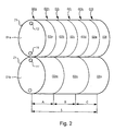
- This cylinder 01 may be configured as a forme cylinder 01 a or as a transfer cylinder 01 b and may be arranged in the circumferential direction next to each other with z.
- the elevators are preferably designed as plate-shaped printing plates; in the case of a transfer cylinder, the elevators are preferably rubber blankets each applied to a carrier plate.
- the printing unit can, for. Example, be designed as a 9-cylinder satellite printing unit in which four pairs each consisting of a forme cylinder 01 a and a transfer cylinder 01b are arranged in a frame around a common impression cylinder, wherein the forme cylinder 01a and transfer cylinder 01b respectively the features of have proposed solution here.
- a forme cylinder 01a in its axial direction in a first row z. B. with six plate-shaped printing plates 02a; 02b; 02c; 02d; 02e; 02f and - in the Fig. 2 only indicated - on the not visible in the representation page of the forme cylinder 01a in a second row z. B.
- two rubber blankets 02m; 02n; 02o occupied transfer cylinder 01b in this case preferably have the same geometric dimensions with respect to the length L of their bale and its circumference.
- the plate-shaped printing plates 02a to 02l are with their respective ends 03; 04 on the forme cylinder 01a in two circumferentially offset by 180 ° channels 11; 12 attached, whereas the respective ends 03; 04 of rubber blankets 02m; 02n; 02o are held in at least one channel 11 ⁇ .
- the forme cylinder 01 a and the transfer cylinder 01 b are preferably arranged in the printing unit such that their respective channels 11; 11 ⁇ roll on each other.
- the forme cylinder 01a can also be occupied by elevators designed as panorama printing plates, so that each plate-shaped printing form contains two printed image pages in each case.
- those in the Fig. 2 for the elevators assigned reference numerals 02a to 02l on the printed image pages, wherein the printed image pages 02a; 02b and 02c, respectively; 02d and 02e, respectively; 02f or 02g; 02h or 02i; 02j or 02k; 02l are each arranged on a panoramic printing plate.
- elevators are arranged offset in the circumferential direction of the cylinder to each other, this means in the case of using Panorama printing plates that not the individual printed pages, but arranged on the lateral surface 13 of the cylinder 01a, each consisting of two printed pages panorama printing plates are arranged offset from one another.
- the elevators In order to allow a staggered arrangement of elevators, in a cylinder with two channels, the elevators must either fully span the cylinder circumferentially, with both ends of the same elevator fixed in the same channel and the ends of an adjacent elevator in the other channel, or are in the Cylinder but more than two channels provided, such.
- two elevators circumferentially one behind the other can be arranged, the ends of each elevator are mounted in two different, each offset by 180 ° channels and adjacent elevators are secured in the offset by 90 ° channels.
- the cylinder 01; 01 a; 01 b has a diameter D1 of, for example, 160 mm to 340 mm, preferably between 280 mm and 300 mm.
- the axial length L of the bale of the cylinder 01, 01a; 01 b is z. B. in the range between 1200 mm and 2400 mm, preferably between 1900 mm and 2300 mm Fig. 1 ,
- a plate-shaped printing plate or a support plate for a rubber blanket is usually made of a flexible, but otherwise dimensionally stable material, eg. B. of an aluminum alloy, and has two opposite, in or on the cylinder 01; 01 a; 01 b to be fastened ends 03; 04 with a material thickness M of z. B.
- a first channel 11 and a second channel 12 are provided in the cylinder 01, wherein both channels 11; 12 extend continuously in the direction of the length L of the cylinder 01 and in the direction of its circumference z. B. are offset by a 180 ° spanning circular arc to each other.
- the channels 11; 12 equidistant, ie to arrange at equal distances from each other.
- Both channels 11; 12 are in the interior of the cylinder 01 at a distance a of z. B. 4 mm to 10 mm, preferably 6 mm under the lateral surface 13 as a preferably circular bore through the cylinder 01 and each have a diameter D2 of z. B. 25 mm to 50 mm, preferably 30 mm.
- the ratio of the diameter D1; D2 from the cylinder 01 to the channel 11; 12 is thus preferably at 10: 1.
- the ratio of the cross-sectional areas of the cylinder 01 to one of the channels 11; Preferably at 100: 1, such that the cross-sectional area of the channels 11; 12 is comparatively small to that of the cylinder 01.
- both channels 11; 12 in its longitudinal direction in so many sections A; B; C; D split, as elevators 02a; 02b; 02c; 02d can be arranged side by side on the lateral surface 13 of the cylinder 01, wherein the sectionwise division of the lateral surface 13 of those of the channels 11; 12 corresponds.
- the channels 11; 12 have in some of their sections A; B; C; D a narrow, slit-shaped opening 14 to the lateral surface 13 of the cylinder 01 on ( Fig. 5 ).
- the slot width S of the opening 14 is less than 5 mm and is preferably in the range of 1 mm to 3 mm ( Fig. 4 ).
- Fig. 5 corresponds in this example, the number of in each channel 11; 12 arranged side by side in the longitudinal direction, provided with an opening 14 sections A; B; C; D half of the length L of the cylinder 01 offset juxtaposed elevators 02a; 02b; 02c; 02d. If the lateral surface 13 of the cylinder 01 is occupied in the circumferential direction next to each other with more than one elevator, more than two, each spaced in a particular circular arc channels or sections of channels are provided and it results from the larger number of elevators complex occupancy arrangements on the Lateral surface 13 of the cylinder 01.
- the number of elevators 02a; 02b; 02c; 02d and sections A; B; C; D are each selected to four, here each section A; B; C; D1 ⁇ 4 the length L of the cylinder 01 has.
- all elevators are 02a; 02b; 02c; 02d on the lateral surface 13 of the cylinder 01 in the axial direction next to each other and the elevators 2b and 02d offset to the elevators 2a and 2c arranged such that these elevators 2b and 02d cover the sections B and D of the channel 12, whereas the elevators 2a and 2c Cover the sections A and C of the channel 11.
- the channel 11 has only in the sections B and D an opening 14 to the lateral surface 13 of the cylinder 01, while the channel 12 in the sections A and C each have a corresponding opening 14.
- the elevators 02a; 02b; 02c; 02d span in this example in each case the entire circumference of the cylinder 01.
- the ends 03; 04 of the elevators 02a; 02c fixed in the same channel 12, whereas the ends 03; 04 of the elevators 02b; 02d are secured in the other channel 11.
- Every elevator 02a; 02b; 02c; 02d thus covers each section A; B; C; D one of the two channels 11; 12, while he with his two ends 03; 04 in the other channel 11; 12 is attached.
- the openings 14 introduced into the lateral surface 13 of the cylinder 01 are aligned with each other.
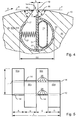
- each elevator 02a to 02o molded suspension legs 06; 07 are inserted into the respective opening 14. It is advantageous in each case to mount a suspension leg 06 of each elevator 02a to 02o in a form-fitting manner on a first wall 17, this first wall 17 being bounded by an opening P of the cylinder 01; 01a; 01b leading edge 16 of the opening 14 to the interior of the channel 11 ';11; 12 extends.
- the angle ⁇ formed at one end 03 of the elevator 02a to 02o preferably corresponds to the angle ⁇ which extends between this first and the interior of the channel 11 ';11; 12 extending wall 17 and an imaginary, resting on the opening 14 tangent T results.
- each elevator 02a to 02o can be applied to a second wall 19, wherein this second wall 19 of a in the direction of production P of the cylinder 01; 01a; 01 b trailing edge 18 of the opening 14 to the interior of the channel 11 ⁇ ; 11; 12 extends.
- the angle ⁇ formed at one end 04 of the elevator 02a to 02o advantageously corresponds to the angle ⁇ which exists between the second one to the interior of the channel 11 ⁇ ; 11; 12 extending wall 19 and an imaginary, resting on the opening 14 tangent T gives ( Fig. 3 and Fig. 4 ).
- a holding device is provided, wherein the holding device consists of at least one clamping piece 21 and a spring element 22.
- the inserted into the opening 14 suspension leg 07 ( Fig. 3 ) at the trailing end 04 of the elevators 02a to 02o is preferably applied to the second wall 19 of the opening 14 and pressed there by the clamping piece 21 by a force exerted by the spring element 22 on the clamping piece 21 force F.
- an adjusting means 23 is provided, which counteracts in its actuation of the force exerted by the spring element 22 on the clamping piece 21 force F and the clamping piece 21 pivots away from the second wall 19 of the opening 14.
- said base body 24 is preferably configured substantially as a cylindrical hollow body whose outer diameter D3 is slightly smaller than the diameter D2 of a channel 11; 11; 12 is and due to its design in the channel 11; 11; 12 is supported, wherein the clamping piece 21 is pivotally mounted in the interior or at the bottom 27 of this base body 24. It is advantageous, the support of the base body 24 in the channel 11 ⁇ ; 11; 12 to be combined with a rotation of the base body 24 by, for example, on the base body 24, a stop is formed, the z.
- Each base body 24 can for its preferably positive connection frontally with a tongue and groove joint 28; Be provided 29 or connector.
- the length I1 of the manufactured as a piece base body 24 may, for. B. between 30 mm and 100 mm and preferably 60 mm ( Fig. 6 ).
- sections A; B; C; D in which a holding device for securing a Einpatinlegeels 06; 07 is not required by one of the elevators 02a to 02o, ie R. in sections A; B; C; D without opening 14, is the introduction of a provided with a holding device base body 24 in the channel 11 ⁇ ; 11; 12 neither necessary nor economical.
- filling elements 26 are provided which may be similar in their outer contour of those of the base body 24, wherein the filling elements 26 have in their interior, however, no holding device and thus are less expensive ( Fig. 6 ).
- the filling elements 26 are based on the length of the sections A; B; C; D preferably designed as a comparatively short sections with a length 12, wherein the length 12 as well as the length I1 of the base body 24 z. B. between 30 mm and 100 mm and may be preferably 60 mm.
- groups of about five to six preferably identical base bodies 24 or filling elements 26 are arranged, these groups in turn being arranged alternately.
- the base body 24 and the filling elements 26 are preferably made a plastic as an injection molded part or made of another easily workable material. It is intended, everywhere in those sections A; B; C; D in the channel 11; 12 to arrange filling elements 26 lined up, which are closed, that is to the lateral surface 13 of the cylinder 01; 01a, 01b have no opening 14.
- adjusting means 23 for the holding device in the base bodies 24 is preferably one with a pressure medium, for. B. compressed air, acted upon hose provided in the channel 11 ⁇ ; 11; 12 advantageously continuously from one to the other end face of the cylinder 01; 01a; 01b can be laid.
- a pressure medium for. B. compressed air, acted upon hose provided in the channel 11 ⁇ ; 11; 12 advantageously continuously from one to the other end face of the cylinder 01; 01a; 01b can be laid.
- the filling elements 26 is provided to design the filling elements 26 as a substantially cylindrical hollow body.
- the groove Spring connection 28; 29 or connector are used by their arrangement and shape to line up the base body 24 and filling elements 26 both with each other and to each other with its through hole 31 in alignment.
- the same anti-rotation can be formed on the filling elements 26 as on the base bodies 24.
- a continuous from one to the other end face of the cylinder 01; 01a; 01b arranged adjusting means 23 allows the holding device in several base bodies 24, in the same channel 11 ⁇ ; 11; 12 are arranged to operate simultaneously and together. It is advantageous to ensure that at least all the holding devices which are in the same section A; B; C; D of a channel 11 ⁇ ; 11; 12 are arranged, can be operated simultaneously and together. This configuration results in that the holding devices are then actuated in sections.
- channel 11 or the channels 11; 12 in the cylinder 01; 01 a; 01b are configured, whether they consistently from one to the other end face of the cylinder 01; 01a; 01b or only in the respective sections A; B; C; D are formed as sections is, according to the proposed solution for a cylinder 01; 01a; 01 b apply to the circumference and the length L, wherein the lateral surface 13 of the cylinder 01; 01a; 01b over the length L in at least three juxtaposed sections A; B; C; D is divided, that the lateral surface 13 in at least three sections A; B; C; D each having at least one slot-shaped opening 14, wherein at least two in two different sections A; B; C; D arranged openings 14 with respect to the circumference of the cylinder 01; 01a; 01b are arranged offset from each other.
- each opening 14 may be at least a portion of a below the lateral surface 13 of the cylinder 01; 01 a; 01 b extending channel 11 ⁇ ; 11; 12 open.
Landscapes
- Supply, Installation And Extraction Of Printed Sheets Or Plates (AREA)
- Rotary Presses (AREA)
- Inking, Control Or Cleaning Of Printing Machines (AREA)
- Printers Characterized By Their Purpose (AREA)
Abstract
Description
Die Erfindung betrifft einen Zylinder eines Druckwerks einer Rotationsdruckmaschine mit einem oder mehreren Aufzügen gemäß dem Oberbegriff des Anspruches 1.The invention relates to a cylinder of a printing unit of a rotary printing machine with one or more elevators according to the preamble of claim 1.
Aus der
Die
Aus der
Der Erfindung liegt die Aufgabe zugrunde, einen Zylinder eines Druckwerks einer Rotationsdruckmaschine mit einem oder mehreren Aufzügen zu schaffen.The invention has for its object to provide a cylinder of a printing unit of a rotary printing machine with one or more elevators.
Die Aufgabe wird erfindungsgemäß durch die Merkmale des Anspruches 1 gelöst.The object is achieved by the features of claim 1.
Die mit der Erfindung erzielbaren Vorteile bestehen insbesondere darin, dass in den Kanälen des Zylinders preiswerte Basiskörper und Füllelemente montagefreundlich anordenbar sind. Dabei sind insbesondere die Füllelemente auf nahezu jede beliebige Länge konfektionierbar. Ein mit einer Öffnung versehener Kanal, der von einem Aufzug abschnittsweise überdeckt ist, birgt für diesen Aufzug die Gefahr eines Bruchs beim Abrollen auf einem Gegenzylinder in einem Druckwerk. Diese Gefahr besteht nicht bei einem Zylinder mit Kanälen, die nur in denjenigen Abschnitten eine Öffnung aufweisen, in denen diese Öffnung zur Befestigung eines Aufzugs auf der Mantelfläche des Zylinders erforderlich ist.The advantages that can be achieved with the invention are, in particular, that inexpensive base bodies and filling elements can be arranged in an easy-to-install manner in the channels of the cylinder. In particular, the filling elements can be assembled to almost any desired length. An opening provided with a channel, which is partially covered by an elevator, holds for this elevator the risk of breakage when unrolling on a counter-cylinder in a printing unit. This danger does not exist with a cylinder with channels which have an opening only in those sections where this opening is required for mounting an elevator on the lateral surface of the cylinder.
Ausführungsbeispiele der Erfindung sind in den Zeichnungen dargestellt und werden im Folgenden näher beschrieben.Embodiments of the invention are illustrated in the drawings and will be described in more detail below.
Es zeigen:
- Fig. 1
- eine perspektivische Ansicht eines Zylinders mit zwei Kanälen und vier nebeneinander anordenbaren Aufzügen;
- Fig. 2
- eine vereinfachte Darstellung eines Druckwerks mit einem 6/2-Formzylinder und einem Übertragungszylinder (Einfachumfang);
- Fig. 3
- eine perspektivische Ansicht eines Aufzugs;
- Fig. 4
- eine Teilschnittdarstellung eines Zylinders mit einem Kanal und einer darin angeordneten Vorrichtung zum Befestigen eines Aufzugs auf einem Zylinder;
- Fig. 5
- eine ebene Abwicklung von vier nebeneinander versetzt auf einem Zylinder angeordneten Aufzügen;
- Fig. 6
- eine vereinfachte perspektivische Ansicht eines Basiskörpers oder Füllelements.
- Fig. 1
- a perspective view of a cylinder with two channels and four juxtaposed lifts;
- Fig. 2
- a simplified representation of a printing unit with a 6/2 forme cylinder and a transfer cylinder (single circumference);
- Fig. 3
- a perspective view of an elevator;
- Fig. 4
- a partial sectional view of a cylinder with a channel and a device arranged therein for securing an elevator on a cylinder;
- Fig. 5
- a flat development of four side by side offset on a cylinder arranged elevators;
- Fig. 6
- a simplified perspective view of a base body or filler.
In der
Bei einem Formzylinder sind die Aufzüge vorzugsweise als plattenförmige Druckformen ausgebildet, bei einem Übertragungszylinder handelt es sich bei den Aufzügen vorzugsweise um jeweils auf einer Trägerplatte aufgebrachte Gummidrucktücher.In the case of a forme cylinder, the elevators are preferably designed as plate-shaped printing plates; in the case of a transfer cylinder, the elevators are preferably rubber blankets each applied to a carrier plate.
Das Druckwerk kann z. B. als eine 9-Zylinder-Satelliten-Druckeinheit ausgebildet sein, bei dem vier Paare jeweils bestehend aus einem Formzylinder 01 a und einem Übertragungszylinder 01b in einem Gestell um einen gemeinsamen Gegendruckzylinder angeordnet sind, wobei die Formzylinder 01a und Übertragungszylinder 01b jeweils die Merkmale der hier vorgeschlagenen Lösung aufweisen. Gerade für den Zeitungsdruck sind Anordnungen günstig (
Wenn nun, wie später noch beschrieben wird, Aufzüge in Umfangsrichtung des Zylinders zueinander versetzt angeordnet werden, bedeutet das im Fall einer Verwendung von Panoramadruckplatten, dass nicht die einzelnen Druckseiten, sondern die auf der Mantelfläche 13 des Zylinders 01a zu befestigenden, jeweils aus zwei Druckseiten bestehenden Panoramadruckplatten zueinander versetzt angeordnet sind. Um eine versetzte Anordnung von Aufzügen zu ermöglichen, müssen bei einem Zylinder mit zwei Kanälen die Aufzüge entweder den Zylinder umfangsmäßig voll umspannen, wobei beide Enden desselben Aufzugs im selben Kanal und die Enden eines benachbarten Aufzugs in dem anderen Kanal befestigt sind, oder es sind im Zylinder doch mehr als zwei Kanäle vorgesehen, so z. B. vier Kanäle, die jeweils um 90° zueinander versetzt angeordnet sind, so dass jeweils z. B. zwei Aufzüge umfangsmäßig hintereinander anordenbar sind, wobei die Enden jedes Aufzugs in zwei unterschiedlichen, jeweils um 180° versetzten Kanälen befestigt werden und benachbarte Aufzüge in den dazu um 90° versetzten Kanälen befestigt sind.If now, as will be described later, elevators are arranged offset in the circumferential direction of the cylinder to each other, this means in the case of using Panorama printing plates that not the individual printed pages, but arranged on the
Der Zylinder 01; 01 a; 01 b hat einen Durchmesser D1 von beispielsweise 160 mm bis 340 mm, vorzugsweise zwischen 280 mm und 300 mm. Die axiale Länge L des Ballens des Zylinders 01, 01a; 01 b liegt z. B. im Bereich zwischen 1200 mm und 2400 mm, vorzugsweise zwischen 1900 mm und 2300 mm
In dem in der
Beide Kanäle 11; 12 sind im Inneren des Zylinders 01 in einem Abstand a von z. B. 4 mm bis 10 mm, vorzugsweise 6 mm unter dessen Mantelfläche 13 als eine vorzugsweise kreisrunde Bohrung durch den Zylinder 01 ausgeführt und weisen jeweils einen Durchmesser D2 von z. B. 25 mm bis 50 mm, vorzugsweise 30 mm auf. Das Verhältnis der Durchmesser D1; D2 vom Zylinder 01 zum Kanal 11; 12 liegt damit vorzugsweise bei 10:1. Wenn die Querschnittsfläche der Kanäle 11; 12 nicht kreisrund ist, liegt das Verhältnis der Querschnittsflächen vom Zylinder 01 zu einem der Kanäle 11; 12 vorzugsweise bei 100:1, so dass die Querschnittsfläche der Kanäle 11; 12 vergleichsweise gering zu derjenigen des Zylinders 01 ist.Both
In dem in der
Die Schlitzweite S der Öffnung 14 beträgt weniger als 5 mm und liegt vorzugsweise im Bereich von 1 mm bis 3 mm (
Wie die
In diesem Beispiel wurde die Anzahl der Aufzüge 02a; 02b; 02c; 02d und Abschnitte A; B; C; D jeweils zu vier gewählt, wobei hier jeder Abschnitt A; B; C; D¼ der Länge L des Zylinders 01 aufweist. Wie die
Die an den Enden 03; 04 jedes Aufzugs 02a bis 02o angeformten Einhängeschenkel 06; 07 werden in die jeweilige Öffnung 14 eingeführt. Es ist vorteilhaft, jeweils einen Einhängeschenkel 06 jedes Aufzugs 02a bis 02o an einer ersten Wandung 17 formschlüssig einzuhängen, wobei sich diese erste Wandung 17 von einer in Produktionsrichtung P des Zylinders 01; 01a; 01b vorlaufenden Kante 16 der Öffnung 14 zum Inneren des Kanals 11'; 11; 12 erstreckt. Der an einem Ende 03 des Aufzugs 02a bis 02o angeformte Winkel α entspricht vorzugsweise dem Winkel α, der sich zwischen dieser ersten zum Inneren des Kanals 11'; 11; 12 erstreckenden Wandung 17 und einer gedachten, auf der Öffnung 14 aufliegenden Tangente T ergibt. Auch der andere Einhängeschenkel 07 jedes Aufzugs 02a bis 02o ist an einer zweiten Wandung 19 anlegbar, wobei sich diese zweite Wandung 19 von einer in Produktionsrichtung P des Zylinders 01; 01a; 01 b nachlaufenden Kante 18 der Öffnung 14 zum Inneren des Kanals 11`; 11; 12 erstreckt. Wiederum entspricht der an einem Ende 04 des Aufzugs 02a bis 02o angeformte Winkel β vorteilhafterweise dem Winkel β, der sich zwischen dieser zweiten zum Inneren des Kanals 11`; 11; 12 erstreckenden Wandung 19 und einer gedachten, auf der Öffnung 14 aufliegenden Tangente T ergibt (
Wie in
Zur leichteren Montage der Haltevorrichtung im Kanal 11`; 11; 12 ist vorgesehen, die zumindest aus einem Klemmstück 21 und einem Federelement 22 bestehende Haltevorrichtung in einem Basiskörper 24 anzuordnen, wobei dieser Basiskörper 24 vorzugsweise im wesentlichen als ein zylindrischer Hohlkörper ausgestaltet ist, dessen Außendurchmesser D3 geringfügig geringer als der Durchmesser D2 eines Kanals 11; 11; 12 ist und der sich aufgrund seiner Gestaltung im Kanal 11; 11; 12 abstützt, wobei das Klemmstück 21 im Inneren oder am Grund 27 dieses Basiskörpers 24 schwenkbar gelagert ist. Es ist vorteilhaft, die Abstützung des Basiskörpers 24 im Kanal 11`; 11; 12 mit einer Verdrehsicherung des Basiskörpers 24 zu kombinieren, indem beispielsweise am Basiskörper 24 ein Anschlag angeformt ist, der sich z. B. im Kanal 11'; 11; 12 oder an einer der zu den Kanten 16; 18 der Öffnung 14 erstreckenden Wandungen 17; 19 abstützt. Aufgrund der beachtlichen Längen der Abschnitte A; B; C; D, die jeweils zudem in Abhängigkeit von der Länge L des Ballens des jeweiligen Zylinders 01; 01 a; 01 b in ihrem Maß variieren, ist zur einfacheren Anpassung an jede für sie erforderliche Länge vorgesehen, die für jeden Abschnitt A; B; C; D erforderlichen Basiskörper 24 nicht einstückig auszuführen, sondern den Basiskörper 24 als ein im Vergleich zu den Längen der Abschnitte A; B; C; D kurzes Teilstück mit der Länge I1 zu fertigen, wobei dann mehrere vorzugsweise gleichartige Basiskörper 24 im Kanal 11'; 11; 12 für die erforderliche Länge der Abschnitte A; B; C; D aneinandergereiht werden. Jeder Basiskörper 24 kann für seine vorzugsweise formschlüssige Verbindung stirnseitig mit einer Nut-Feder-Verbindung 28; 29 oder Steckverbindung versehen sein. Die Länge I1 des als ein Teilstück gefertigten Basiskörpers 24 kann z. B. zwischen 30 mm und 100 mm liegen und vorzugsweise 60 mm betragen (
In den Abschnitten A; B; C; D, in denen eine Haltevorrichtung zum Befestigen eines Einhängeschenkels 06; 07 von einem der Aufzüge 02a bis 02o nicht benötigt wird, d. h. i. d. R. in den Abschnitten A; B; C; D ohne Öffnung 14, ist die Einbringung eines mit einer Haltevorrichtung versehenen Basiskörpers 24 in den Kanal 11`; 11; 12 weder erforderlich noch wirtschaftlich. Für diese Abschnitte A; B; C; D sind Füllelemente 26 vorgesehen, die in ihrer äußeren Kontur derjenigen der Basiskörper 24 ähneln können, wobei die Füllelemente 26 in ihrem Inneren jedoch keine Haltevorrichtung aufweisen und damit kostengünstiger sind (
Es ist von Vorteil, die Füllelemente 26 derart auszugestalten, dass sie durch einen einfachen Bearbeitungsschritt, z. B. durch Schneiden oder Sägen, auf jede beliebige Länge kürzbar sind. Die Basiskörper 24 sowie die Füllelemente 26 sind vorzugsweise aus einem Kunststoff als ein Spritzgießteil oder aus einem anderen leicht bearbeitbaren Werkstoff gefertigt. Es ist vorgesehen, überall in denjenigen Abschnitten A; B; C; D im Kanal 11; 12 Füllelemente 26 aneinandergereiht anzuordnen, die geschlossen sind, d. h. die zur Mantelfläche 13 des Zylinders 01; 01a, 01b keine Öffnung 14 aufweisen. Um die einzelnen Füllelemente 26 miteinander zu verbinden bzw. jeweils ein erstes oder letztes Füllelement 26 in einer Reihe von mehreren Füllelementen 26 mit einem im selben Kanal 11; 12 angeordneten Basiskörper 24 zu verbinden, können die Füllelemente 26 an ihrer Stirnseite 32 dieselbe Nut-Feder-Verbindung 28; 29 oder Steckverbindung aufweisen wie die Basiskörper 24. Um das Füllelement 26 bezüglich seiner Verbindbarkeit mit anderen Füllelementen 26 oder Basiskörpern 24 nach einer Kürzung in seiner Länge I2 funktionsfähig zu erhalten, ist die in ihm eingebrachte Nut 28 mit einer Länge I3 über einen großen Teil der Länge I2 des Füllelements 26 ausgeführt, wobei die Länge I3 bis zu 70% von der Länge I2 betragen kann.It is advantageous to design the filling
Als Stellmittel 23 für die Haltevorrichtung in den Basiskörpern 24 ist vorzugsweise ein mit einem Druckmittel, z. B. Druckluft, beaufschlagbarer Schlauch vorgesehen, der im Kanal 11 `; 11; 12 vorteilhafterweise durchgängig von einer zur anderen Stirnseite des Zylinders 01; 01a; 01b verlegbar ist. Zu diesem Zweck ist vorgesehen, auch die Füllelemente 26 als einen im wesentlichen zylindrischen Hohlkörper auszugestalten. Bei dieser Ausgestaltung weisen sowohl die Basiskörper 24 als auch die Füllelemente 26 ein Durchgangsloch 31 auf, durch das bei einer Aneinanderreihung der Basiskörper 24 und Füllelemente 26 im selben Kanal 11; 12 der Schlauch hindurchgeführt werden kann. Insbesondere wenn das Durchgangsloch 31 in den Basiskörpern 24 und Füllelementen 26 außermittig angeordnet oder bezüglich einer durch ihren jeweiligen Mittelpunkt O verlaufenden Linie Sy, wobei der Mittelpunkt O und die durch ihn verlaufende Linie Sy in derselben Querschnittsebene X-X liegen, unsymmetrisch ausgestaltet ist, kann die Nut-Feder-Verbindung 28; 29 oder Steckverbindung durch ihre Anordnung und Formgebung dazu genutzt werden, die Basiskörper 24 und Füllelemente 26 sowohl untereinander als auch zueinander mit ihrem Durchgangsloch 31 fluchtend aneinanderzureihen. Wenn die Basiskörper 24 im Kanal 11; 12 verdrehsicher angeordnet sind, wird durch die formschlüssige Verbindung aller im selben Kanal 11; 12 angeordneten Basiskörper 24 und Füllelemente 26 auch eine ausreichende Verdrehsicherung der Füllelemente 26 erreicht. Nötigenfalls kann auch an den Füllelementen 26 dieselbe Verdrehsicherung angeformt sein wie an den Basiskörpern 24. Ein durchgängig von einer zur anderen Stirnseite des Zylinders 01; 01a; 01b angeordnetes Stellmittel 23 gestattet es, die Haltevorrichtung in mehreren Basiskörpern 24, die im selben Kanal 11`; 11; 12 angeordnet sind, gleichzeitig und gemeinsam zu betätigen. Es ist vorteilhaft sicherzustellen, dass zumindest alle Haltevorrichtungen, die im selben Abschnitt A; B; C; D eines Kanals 11`; 11; 12 angeordnet sind, gleichzeitig und gemeinsam betätigt werden können. Diese Ausgestaltung führt dazu, dass die Haltevorrichtungen dann abschnittsweise betätigbar sind.As adjusting means 23 for the holding device in the
Unabhängig davon, wie der Kanal 11 oder die Kanäle 11; 12 im Zylinder 01; 01 a; 01b ausgestaltet sind, ob sie durchgängig von einer zur anderen Stirnseite des Zylinders 01; 01a; 01b sind oder nur in den jeweiligen Abschnitten A; B; C; D als Teilstücke ausgebildet sind, soll gemäß der hier vorgeschlagenen Lösung für einen Zylinder 01; 01a; 01 b mit dem Umfang sowie der Länge L gelten, wobei die Mantelfläche 13 des Zylinders 01; 01a; 01b über die Länge L in mindestens drei aneinandergereihte Abschnitte A; B; C; D unterteilt ist, dass die Mantelfläche 13 in mindestens drei Abschnitten A; B; C; D jeweils mindestens eine schlitzförmige Öffnung 14 aufweist, wobei mindestens zwei in zwei unterschiedlichen Abschnitten A; B; C; D angeordnete Öffnungen 14 bezüglich des Umfangs des Zylinders 01; 01a; 01b zueinander versetzt angeordnet sind. Dabei fluchten vorzugsweise zwei in zwei unterschiedlichen Abschnitten A; B; C; D angeordnete Öffnungen 14 miteinander. Jede Öffnung 14 mag dabei zumindest ein Teilstück von einem sich unter der Mantelfläche 13 des Zylinders 01; 01 a; 01 b erstreckenden Kanal 11`; 11; 12 öffnen.Regardless of how the
- 0101
- Zylindercylinder
- 01 a01 a
- Formzylinderform cylinder
- 01 b01 b
- Ü bertragungszylinderTransfer cylinder
- 02a bis 02l02a to 02l
- Aufzug, Druckform,Elevator, printing form,
- 02m bis 02o02m to 02o
- Aufzug, Druckform, GummidrucktuchElevator, printing form, rubber blanket
- 03;0403, 04
- Endenend up
- 0505
- --
- 06; 0706; 07
- Einhängeschenkelsuspension leg
- 08; 0908; 09
- Biegelinieelastic line
- 1010
- --
- 11'; 11; 1211 '; 11; 12
- Kanälechannels
- 1313
- Mantelflächelateral surface
- 1414
- Öffnungopening
- 1515
- --
- 1616
- vorlaufende Kanteleading edge
- 1717
- erste Wandungfirst wall
- 1818
- nachlaufende Kantetrailing edge
- 1919
- zweite Wandungsecond wall
- 2020
- --
- 2121
- Klemmstückclamp
- 2222
- Federelementspring element
- 2323
- Stellmittelactuating means
- 2424
- Basiskörperbase body
- 2525
- --
- 2626
- Füllelementfiller
- 2727
- Grund (24)Reason (24)
- 2828
- Nutgroove
- 2929
- Federfeather
- 3030
- --
- 3131
- DurchgangslochThrough Hole
- 3232
- Stirnseitefront
- A, B, C; DA, B, C; D
- Abschnittesections
- D1D1
- Durchmesser des ZylindersDiameter of the cylinder
- D2D2
- Durchmesser des KanalsDiameter of the channel
- D3D3
- Außendurchmesserouter diameter
- MM
- Materialstärkematerial thickness
- PP
- Produktionsrichtungproduction direction
- SS
- Schlitzweiteslot width
- FF
- Kraftforce
- aa
- Abstanddistance
- LL
- Längelength
- OO
- MittelpunktFocus
- Sysy
- Linieline
- X-XX X
- QuerschnittsebeneCross-sectional plane
- II
- Längelength
- I1I1
- Längelength
- I2I2
- Längelength
- I3I3
- Längelength
Claims (24)
- Cylinder (01; 01 a; 01 b) of a printing unit of a rotary printing press having one or more packings (02a to 02o) arranged on the lateral surface (13) thereof,
an axial length (L) of the cylinder (01; 01 a; 01 b) being divided into a plurality of successive sections (A; B; C; D),
one or more packings (02a to 02o) being arranged in one or more sections (A; B; C; D) in the circumferential direction of the cylinder (01; 01 a; 01 b),
the width of the packings (02a to 02o) corresponding in each case to the width of one or more sections (A; B; C; D),
at least two channels (11; 11'; 12) which are arranged offset relative to one another on the circumference of the cylinder (01; 01 a; 01 b) and which extend in each case in the axial direction of the cylinder (01; 01 a; 01 b) under the lateral surface (13) thereof and in each case have an opening (14) to the lateral surface (13) in the region of at least one section (A; B; C; D) being provided,
at least one channel (11; 11'; 12) extending in at least one section (A; B; C; D) under a packing (02a to 02o) arranged in this section (A; B; C; D) on the lateral surface (13),
characterized in that a plurality of base bodies (24) having in each case a retaining device (21; 22) for the end (03; 04) are arranged side by side in the axial direction for fixing the packings (02a to 02o) in the channels (11; 11'; 12) in those sections (A; B; C; D) in which at least one end (03; 04) of at least one packing (02a to 02o) extends through an opening (14) into the respective channel (11; 11'; 12),
and in that, in the at least one channel (11; 11'; 12) which extends at least in one section (A; B; C; D) under a packing (02a to 02o) arranged in this section (A; B; C; D) on the lateral surface (13), a plurality of filling elements (26) without retaining device (21; 22) are arranged side by side in the axial direction instead of the base bodies (24) in this section (A; B; C; D) extending under the packing (02a to 02o). - Cylinder (01; 01 a; 01 b) having packings (02a to 02o) according to Claim 1,
characterized in that at least one channel (11; 11'; 12) in at least one section (A; B; C; D) is closed on the lateral surface (13). - Cylinder (01; 01 a; 01 b) having packings (02a to 02o) according to Claim 2,
characterized in that a plurality of filling elements (26) are arranged side by side in the axial direction instead of the base bodies (24) in the channels (11; 11'; 12) in the sections (A; B; C; D) closed at the lateral surface (13). - Cylinder (01; 01 a; 01 b) having packings (02a to 02o) according to Claim 1,
characterized in that at least one group of base bodies (24) and at least one group of filling elements (26) are arranged in each channel (11; 11'; 12) and that these groups are arranged alternately. - Cylinder (01; 01 a; 01 b) having packings (02a to 02o) according to Claim 1,
characterized in that the length of the at least one opening (14) in each channel (11; 11'; 12) corresponds to the length of the respective section (A; B; C; D). - Cylinder (01; 01 a; 01 b) having packings (02a to 02o) according to Claim 1,
characterized in that a respective length (11; I2) of both the base bodies (24) and the filling elements (26) is short in comparison with the sections (A; B; C; D). - Cylinder (01; 01 a; 01 b) having packings (02a to 02o) according to Claim 6,
characterized in that the length (11; 12) of the base bodies (24) or of the filling elements (26) is 30 mm to 100 mm. - Cylinder (01; 01 a; 01 b) having packings (02a to 02o) according to Claim 6,
characterized in that the length (11; 12) of the base bodies (24) or of the filling elements (26) is 60 mm. - Cylinder (01; 01 a; 01 b) having packings (02a to 02o) according to Claim 1,
characterized in that at least two packings (02a to 02o) arranged on the lateral surface (13) of the cylinder (01; 01 a; 01 b) in adjacent sections (A; B; C; D) are arranged offset relative to one another in the circumferential direction of the cylinder (01; 01 a; 01 b). - Cylinder (01; 01 a; 01 b) having packings (02a to 02o) according to Claim 1,
characterized in that each packing (02a to 02o) arranged on the lateral surface (13) of the cylinder (01; 01 a; 01 b) has, at its respective end (03; 04), at least one bent engaging limb (06; 07) insertable into the opening (14) of a channel (11; 11'; 12). - Cylinder (01; 01 a; 01 b) having packings (02a to 02o) according to Claim 10,
characterized in that a retaining device for clamping an engaging limb (06; 07) of one of the packings (02a to 02o) is present in the base bodies (24). - Cylinder (01; 01 a; 01 b) having packings (02a to 02o) according to Claim 1,
characterized in that the base bodies (24) or the filling elements (26) are supported in a nonrotatable manner in the channel (11; 11'; 12). - Cylinder (01; 01 a; 01 b) having packings (02a to 02o) according to Claim 1,
characterized in that the base bodies (24) and the filling elements (26) have, on their end face, a tongue-and-groove joint (28; 29) or a plug connection, by means of which, in each channel (11; 11'; 12), individual base bodies (24) or filling elements (26) can be connected to one another or a base body (24) can be connected to a filling element (26). - Cylinder (01; 01 a; 01 b) having packings (02a to 02o) according to Claim 1,
characterized in that at least two packings (02a to 02o) are fixed in two different channels (11; 11'; 12). - Cylinder (01; 01 a; 01 b) having packings (02a to 02o) according to Claim 1,
characterized in that the base body (24) or the filling element (26) consists of plastic. - Cylinder (01; 01 a; 01 b) having packings (02a to 02o) according to Claim 15,
characterized in that the base body (24) or the filling element (26) is an injection moulded part. - Cylinder (01; 01 a; 01 b) having packings (02a to 02o) according to Claim 1,
characterized in that the base bodies (24) and the filling elements (26) are each in the form of a hollow body. - Cylinder (01; 01 a; 01 b) having packings (02a to 02o) according to Claim 17,
characterized in that the external diameter (D3) of the hollow body is only slightly smaller than the diameter (D2) of a channel (11; 11'; 12). - Cylinder (01; 01 a; 01 b) having packings (02a to 02o) according to Claim 1,
characterized in that each base body (24) and each filling element (26) has a through-hole (31), a plurality of base bodies (24) and filling elements (26) arranged in a series in the same channel (11; 11'; 12) being flush with one another with respect to their through-hole (31). - Cylinder (01; 01 a; 01 b) having packings (02a to 02o) according to Claims 13 and 19, characterized in that the tongue-and-groove joint (28; 29) or plug connection provided on the base bodies (24) and filling elements (26) align, relative to one another, the through-hole (31) in base bodies (24) and filling elements (26) arranged in series.
- Cylinder (01; 01 a; 01 b) having packings (02a to 02o) according to Claim 19,
characterized in that a tube (23) which can be fed with a pressure medium is laid through the through-hole (31) of base bodies (24) and filling elements (26) arranged in series in the same channel (11; 11'; 12). - Cylinder (01; 01 a; 01 b) having packings (02a to 02o) according to Claim 13,
characterized in that a groove (28) of a tongue-and-groove joint (28; 29), made in a filling element (26), has a length (13) which is up to 70% of the length (I2) of the filling element (26). - Cylinder (01; 01 a; 01 b) having packings (02a to 02o) according to Claim 1,
characterized in that the filling elements (26) are similar in their outer contour to those of the base bodies (24). - Cylinder (01; 01 a; 01 b) having packings (02a to 02o) according to Claim 1,
characterized in that the base bodies (24) and/or the filling elements (26) are each formed in the same manner.
Applications Claiming Priority (3)
| Application Number | Priority Date | Filing Date | Title |
|---|---|---|---|
| DE10228970A DE10228970C1 (en) | 2002-06-26 | 2002-06-26 | Web-fed printing machine has printer unit printing width of six axially adjacent pages, with superstructure, at least one roller and folder and two printing towers |
| DE10228970 | 2002-06-26 | ||
| PCT/DE2003/001844 WO2004002742A1 (en) | 2002-06-26 | 2003-06-05 | Cylinder of a printing unit of a rotary printing machine |
Publications (2)
| Publication Number | Publication Date |
|---|---|
| EP1515851A1 EP1515851A1 (en) | 2005-03-23 |
| EP1515851B1 true EP1515851B1 (en) | 2009-03-11 |
Family
ID=29225183
Family Applications (1)
| Application Number | Title | Priority Date | Filing Date |
|---|---|---|---|
| EP03737930A Expired - Lifetime EP1515851B1 (en) | 2002-06-26 | 2003-06-05 | Cylinder of a printing unit of a rotary printing machine |
Country Status (5)
| Country | Link |
|---|---|
| EP (1) | EP1515851B1 (en) |
| AT (1) | ATE425000T1 (en) |
| AU (1) | AU2003245856A1 (en) |
| DE (2) | DE10228970C1 (en) |
| WO (1) | WO2004002742A1 (en) |
Families Citing this family (7)
| Publication number | Priority date | Publication date | Assignee | Title |
|---|---|---|---|---|
| DE102004001934B3 (en) * | 2004-01-14 | 2005-06-23 | Koenig & Bauer Ag | Setting mechanism incorporated in printing machine cylinder has hollow body deformed by application of fluid pressure enclosed by guide at transition between successive hollow spaces within cylinder |
| DE102004033920B4 (en) * | 2004-05-04 | 2006-11-02 | Koenig & Bauer Ag | Printing form of a printing machine and web-fed rotary printing press |
| DE102006017222A1 (en) * | 2005-06-28 | 2007-01-04 | Koenig & Bauer Ag | Cylinder of a rotary printing machine with at least one extending in the axial direction of this cylinder under the lateral surface channel |
| ATE481357T1 (en) * | 2006-11-07 | 2010-10-15 | Koninkl Philips Electronics Nv | WATER PURIFICATION DEVICE |
| DE102006055324B3 (en) * | 2006-11-23 | 2008-04-03 | Koenig & Bauer Aktiengesellschaft | Cylinder for rotary printing machine, e.g. gravure cylinder, has printing plates attached to it whose ends fit into axial profile and are fastened in place by bolt fitting into register component and carrying slide and nut on its outer end |
| DE102007047892B4 (en) | 2007-11-29 | 2010-07-15 | Koenig & Bauer Aktiengesellschaft | Cylinder of a printing machine with at least one extending under the lateral surface in the axial direction of the channel |
| DE102013212917B4 (en) * | 2013-07-03 | 2017-03-16 | Koenig & Bauer Ag | Form cylinder of a rotary printing press and printing unit |
Family Cites Families (6)
| Publication number | Priority date | Publication date | Assignee | Title |
|---|---|---|---|---|
| DE641173C (en) * | 1933-11-11 | 1937-01-23 | Koenig & Bauer Schnellpressfab | Clamping device for flexible printing plates on the forme cylinder of rotary printing machines |
| DE2220652C3 (en) * | 1972-04-27 | 1975-04-17 | Roland Offsetmaschinenfabrik Faber & Schleicher Ag, 6050 Offenbach | Device for attaching printing plates to the plate cylinder of a rotary printing press |
| DE19521645C2 (en) * | 1995-06-14 | 1998-07-09 | Koenig & Bauer Albert Ag | Device for a slit-shaped holding device |
| DE19924786B4 (en) * | 1999-05-29 | 2004-11-04 | Koenig & Bauer Ag | Device for attaching a flexible plate to a cylinder of a rotary printing press |
| DK1310363T3 (en) * | 1999-12-02 | 2004-03-29 | Koenig & Bauer Ag | Printing works in a rotary printing machine |
| DE10058996C1 (en) * | 2000-11-28 | 2002-06-13 | Koenig & Bauer Ag | Pulling-up mechanism fixing device has channel with single one-lever fixing device in each section perpendicular to axial direction of cylinder |
-
2002
- 2002-06-26 DE DE10228970A patent/DE10228970C1/en not_active Expired - Fee Related
-
2003
- 2003-06-05 DE DE50311279T patent/DE50311279D1/en not_active Expired - Lifetime
- 2003-06-05 AT AT03737930T patent/ATE425000T1/en not_active IP Right Cessation
- 2003-06-05 EP EP03737930A patent/EP1515851B1/en not_active Expired - Lifetime
- 2003-06-05 WO PCT/DE2003/001844 patent/WO2004002742A1/en not_active Application Discontinuation
- 2003-06-05 AU AU2003245856A patent/AU2003245856A1/en not_active Abandoned
Also Published As
| Publication number | Publication date |
|---|---|
| AU2003245856A1 (en) | 2004-01-19 |
| WO2004002742A1 (en) | 2004-01-08 |
| EP1515851A1 (en) | 2005-03-23 |
| DE10228970C1 (en) | 2003-11-13 |
| ATE425000T1 (en) | 2009-03-15 |
| DE50311279D1 (en) | 2009-04-23 |
Similar Documents
| Publication | Publication Date | Title |
|---|---|---|
| EP1233862B1 (en) | Printing unit of a printing machine | |
| EP1738905B1 (en) | Cylinder of a rotary printing machine with a slit along the axis of the cylinder | |
| EP1742796A1 (en) | Web-fed rotary presses comprising a modifiable folding assembly | |
| EP1742794A1 (en) | Printing forms of a printing press, and web-fed rotary presses | |
| WO2005108078A1 (en) | Offset printing group pertaining to a printing machine for printing newspapers | |
| EP1515848B1 (en) | Cylinder pair and cylinder of a printing unit of a rotary offset printing machine | |
| DE10016409B4 (en) | Printing unit of a rotary printing machine | |
| WO2009033909A1 (en) | Printing group, printing press, and method for the operation of a printing group | |
| EP1515851B1 (en) | Cylinder of a printing unit of a rotary printing machine | |
| DE102006028434B4 (en) | Printing unit of a printing press with at least two printing units | |
| DE102006055324B3 (en) | Cylinder for rotary printing machine, e.g. gravure cylinder, has printing plates attached to it whose ends fit into axial profile and are fastened in place by bolt fitting into register component and carrying slide and nut on its outer end | |
| DE102007006522B4 (en) | Operating modes of a printing unit of a rotary printing machine | |
| DE102005048918B4 (en) | Rotary press | |
| EP2042314B1 (en) | Cylinder for a printing unit for variable paper web widths | |
| DE102007006523B4 (en) | Operating modes of a printing unit of a rotary printing machine | |
| EP1938978A2 (en) | Printing unit in a rotary printing press | |
| DE20220292U1 (en) | Web-fed printing machine has printer unit printing width of six axially adjacent pages, with superstructure, at least one roller and folder and two printing towers | |
| DE102006027093A1 (en) | Printing device for rotary printing press, has form cylinder working together with transmission cylinder, and channel provided for retaining adjacent printing clothes to extend about two third of surface length | |
| DE102007046372A1 (en) | Cylinder e.g. plate cylinder, for use in nine-cylinder-satellite-printer unit of rotary offset printing machine, has two channels provided in side regions of cylinder such that three channels are partially overlapped in axial direction | |
| DE202006019789U1 (en) | Printing unit for printing machine, has two printing devices vertically arranged to one side of print substrate whereby printing unit is formed as ninth satellite printing unit with impression cylinder same for all printing devices |
Legal Events
| Date | Code | Title | Description |
|---|---|---|---|
| PUAI | Public reference made under article 153(3) epc to a published international application that has entered the european phase |
Free format text: ORIGINAL CODE: 0009012 |
|
| 17P | Request for examination filed |
Effective date: 20041115 |
|
| AK | Designated contracting states |
Kind code of ref document: A1 Designated state(s): AT BE BG CH CY CZ DE DK EE ES FI FR GB GR HU IE IT LI LU MC NL PT RO SE SI SK TR |
|
| AX | Request for extension of the european patent |
Extension state: AL LT LV MK |
|
| DAX | Request for extension of the european patent (deleted) | ||
| GRAP | Despatch of communication of intention to grant a patent |
Free format text: ORIGINAL CODE: EPIDOSNIGR1 |
|
| GRAS | Grant fee paid |
Free format text: ORIGINAL CODE: EPIDOSNIGR3 |
|
| GRAA | (expected) grant |
Free format text: ORIGINAL CODE: 0009210 |
|
| AK | Designated contracting states |
Kind code of ref document: B1 Designated state(s): AT BE BG CH CY CZ DE DK EE ES FI FR GB GR HU IE IT LI LU MC NL PT RO SE SI SK TR |
|
| REG | Reference to a national code |
Ref country code: GB Ref legal event code: FG4D Free format text: NOT ENGLISH |
|
| REG | Reference to a national code |
Ref country code: CH Ref legal event code: EP |
|
| REG | Reference to a national code |
Ref country code: IE Ref legal event code: FG4D Free format text: LANGUAGE OF EP DOCUMENT: GERMAN |
|
| REF | Corresponds to: |
Ref document number: 50311279 Country of ref document: DE Date of ref document: 20090423 Kind code of ref document: P |
|
| PG25 | Lapsed in a contracting state [announced via postgrant information from national office to epo] |
Ref country code: SI Free format text: LAPSE BECAUSE OF FAILURE TO SUBMIT A TRANSLATION OF THE DESCRIPTION OR TO PAY THE FEE WITHIN THE PRESCRIBED TIME-LIMIT Effective date: 20090311 Ref country code: NL Free format text: LAPSE BECAUSE OF FAILURE TO SUBMIT A TRANSLATION OF THE DESCRIPTION OR TO PAY THE FEE WITHIN THE PRESCRIBED TIME-LIMIT Effective date: 20090311 Ref country code: FI Free format text: LAPSE BECAUSE OF FAILURE TO SUBMIT A TRANSLATION OF THE DESCRIPTION OR TO PAY THE FEE WITHIN THE PRESCRIBED TIME-LIMIT Effective date: 20090311 |
|
| NLV1 | Nl: lapsed or annulled due to failure to fulfill the requirements of art. 29p and 29m of the patents act | ||
| PG25 | Lapsed in a contracting state [announced via postgrant information from national office to epo] |
Ref country code: SE Free format text: LAPSE BECAUSE OF FAILURE TO SUBMIT A TRANSLATION OF THE DESCRIPTION OR TO PAY THE FEE WITHIN THE PRESCRIBED TIME-LIMIT Effective date: 20090611 |
|
| REG | Reference to a national code |
Ref country code: IE Ref legal event code: FD4D |
|
| PG25 | Lapsed in a contracting state [announced via postgrant information from national office to epo] |
Ref country code: CZ Free format text: LAPSE BECAUSE OF FAILURE TO SUBMIT A TRANSLATION OF THE DESCRIPTION OR TO PAY THE FEE WITHIN THE PRESCRIBED TIME-LIMIT Effective date: 20090311 Ref country code: IE Free format text: LAPSE BECAUSE OF FAILURE TO SUBMIT A TRANSLATION OF THE DESCRIPTION OR TO PAY THE FEE WITHIN THE PRESCRIBED TIME-LIMIT Effective date: 20090311 Ref country code: ES Free format text: LAPSE BECAUSE OF FAILURE TO SUBMIT A TRANSLATION OF THE DESCRIPTION OR TO PAY THE FEE WITHIN THE PRESCRIBED TIME-LIMIT Effective date: 20090622 Ref country code: EE Free format text: LAPSE BECAUSE OF FAILURE TO SUBMIT A TRANSLATION OF THE DESCRIPTION OR TO PAY THE FEE WITHIN THE PRESCRIBED TIME-LIMIT Effective date: 20090311 Ref country code: PT Free format text: LAPSE BECAUSE OF FAILURE TO SUBMIT A TRANSLATION OF THE DESCRIPTION OR TO PAY THE FEE WITHIN THE PRESCRIBED TIME-LIMIT Effective date: 20090824 |
|
| PG25 | Lapsed in a contracting state [announced via postgrant information from national office to epo] |
Ref country code: RO Free format text: LAPSE BECAUSE OF FAILURE TO SUBMIT A TRANSLATION OF THE DESCRIPTION OR TO PAY THE FEE WITHIN THE PRESCRIBED TIME-LIMIT Effective date: 20090311 Ref country code: SK Free format text: LAPSE BECAUSE OF FAILURE TO SUBMIT A TRANSLATION OF THE DESCRIPTION OR TO PAY THE FEE WITHIN THE PRESCRIBED TIME-LIMIT Effective date: 20090311 |
|
| BERE | Be: lapsed |
Owner name: KOENIG & BAUER A.G. Effective date: 20090630 |
|
| PLBE | No opposition filed within time limit |
Free format text: ORIGINAL CODE: 0009261 |
|
| STAA | Information on the status of an ep patent application or granted ep patent |
Free format text: STATUS: NO OPPOSITION FILED WITHIN TIME LIMIT |
|
| PG25 | Lapsed in a contracting state [announced via postgrant information from national office to epo] |
Ref country code: MC Free format text: LAPSE BECAUSE OF NON-PAYMENT OF DUE FEES Effective date: 20090630 Ref country code: DK Free format text: LAPSE BECAUSE OF FAILURE TO SUBMIT A TRANSLATION OF THE DESCRIPTION OR TO PAY THE FEE WITHIN THE PRESCRIBED TIME-LIMIT Effective date: 20090311 Ref country code: BG Free format text: LAPSE BECAUSE OF FAILURE TO SUBMIT A TRANSLATION OF THE DESCRIPTION OR TO PAY THE FEE WITHIN THE PRESCRIBED TIME-LIMIT Effective date: 20090611 |
|
| 26N | No opposition filed |
Effective date: 20091214 |
|
| PG25 | Lapsed in a contracting state [announced via postgrant information from national office to epo] |
Ref country code: BE Free format text: LAPSE BECAUSE OF NON-PAYMENT OF DUE FEES Effective date: 20090630 |
|
| PG25 | Lapsed in a contracting state [announced via postgrant information from national office to epo] |
Ref country code: AT Free format text: LAPSE BECAUSE OF NON-PAYMENT OF DUE FEES Effective date: 20090605 |
|
| PG25 | Lapsed in a contracting state [announced via postgrant information from national office to epo] |
Ref country code: GR Free format text: LAPSE BECAUSE OF FAILURE TO SUBMIT A TRANSLATION OF THE DESCRIPTION OR TO PAY THE FEE WITHIN THE PRESCRIBED TIME-LIMIT Effective date: 20090612 |
|
| PG25 | Lapsed in a contracting state [announced via postgrant information from national office to epo] |
Ref country code: IT Free format text: LAPSE BECAUSE OF FAILURE TO SUBMIT A TRANSLATION OF THE DESCRIPTION OR TO PAY THE FEE WITHIN THE PRESCRIBED TIME-LIMIT Effective date: 20090311 |
|
| PG25 | Lapsed in a contracting state [announced via postgrant information from national office to epo] |
Ref country code: LU Free format text: LAPSE BECAUSE OF NON-PAYMENT OF DUE FEES Effective date: 20090605 |
|
| PG25 | Lapsed in a contracting state [announced via postgrant information from national office to epo] |
Ref country code: HU Free format text: LAPSE BECAUSE OF FAILURE TO SUBMIT A TRANSLATION OF THE DESCRIPTION OR TO PAY THE FEE WITHIN THE PRESCRIBED TIME-LIMIT Effective date: 20090912 |
|
| PG25 | Lapsed in a contracting state [announced via postgrant information from national office to epo] |
Ref country code: TR Free format text: LAPSE BECAUSE OF FAILURE TO SUBMIT A TRANSLATION OF THE DESCRIPTION OR TO PAY THE FEE WITHIN THE PRESCRIBED TIME-LIMIT Effective date: 20090311 |
|
| PG25 | Lapsed in a contracting state [announced via postgrant information from national office to epo] |
Ref country code: CY Free format text: LAPSE BECAUSE OF FAILURE TO SUBMIT A TRANSLATION OF THE DESCRIPTION OR TO PAY THE FEE WITHIN THE PRESCRIBED TIME-LIMIT Effective date: 20090311 |
|
| PGFP | Annual fee paid to national office [announced via postgrant information from national office to epo] |
Ref country code: DE Payment date: 20120622 Year of fee payment: 10 Ref country code: CH Payment date: 20120626 Year of fee payment: 10 |
|
| PGFP | Annual fee paid to national office [announced via postgrant information from national office to epo] |
Ref country code: GB Payment date: 20120626 Year of fee payment: 10 Ref country code: FR Payment date: 20120704 Year of fee payment: 10 |
|
| REG | Reference to a national code |
Ref country code: CH Ref legal event code: PL |
|
| GBPC | Gb: european patent ceased through non-payment of renewal fee |
Effective date: 20130605 |
|
| REG | Reference to a national code |
Ref country code: FR Ref legal event code: ST Effective date: 20140228 |
|
| REG | Reference to a national code |
Ref country code: DE Ref legal event code: R119 Ref document number: 50311279 Country of ref document: DE Effective date: 20140101 |
|
| PG25 | Lapsed in a contracting state [announced via postgrant information from national office to epo] |
Ref country code: GB Free format text: LAPSE BECAUSE OF NON-PAYMENT OF DUE FEES Effective date: 20130605 Ref country code: CH Free format text: LAPSE BECAUSE OF NON-PAYMENT OF DUE FEES Effective date: 20130630 Ref country code: LI Free format text: LAPSE BECAUSE OF NON-PAYMENT OF DUE FEES Effective date: 20130630 Ref country code: DE Free format text: LAPSE BECAUSE OF NON-PAYMENT OF DUE FEES Effective date: 20140101 |
|
| PG25 | Lapsed in a contracting state [announced via postgrant information from national office to epo] |
Ref country code: FR Free format text: LAPSE BECAUSE OF NON-PAYMENT OF DUE FEES Effective date: 20130701 |