EP1440651A2 - Staubsauger - Google Patents
Staubsauger Download PDFInfo
- Publication number
- EP1440651A2 EP1440651A2 EP04000935A EP04000935A EP1440651A2 EP 1440651 A2 EP1440651 A2 EP 1440651A2 EP 04000935 A EP04000935 A EP 04000935A EP 04000935 A EP04000935 A EP 04000935A EP 1440651 A2 EP1440651 A2 EP 1440651A2
- Authority
- EP
- European Patent Office
- Prior art keywords
- vacuum cleaner
- separation chamber
- cleaner according
- dirt
- dirt bag
- Prior art date
- Legal status (The legal status is an assumption and is not a legal conclusion. Google has not performed a legal analysis and makes no representation as to the accuracy of the status listed.)
- Granted
Links
Images


Classifications
-
- A—HUMAN NECESSITIES
- A47—FURNITURE; DOMESTIC ARTICLES OR APPLIANCES; COFFEE MILLS; SPICE MILLS; SUCTION CLEANERS IN GENERAL
- A47L—DOMESTIC WASHING OR CLEANING; SUCTION CLEANERS IN GENERAL
- A47L9/00—Details or accessories of suction cleaners, e.g. mechanical means for controlling the suction or for effecting pulsating action; Storing devices specially adapted to suction cleaners or parts thereof; Carrying-vehicles specially adapted for suction cleaners
- A47L9/10—Filters; Dust separators; Dust removal; Automatic exchange of filters
- A47L9/14—Bags or the like; Rigid filtering receptacles; Attachment of, or closures for, bags or receptacles
- A47L9/1418—Impermeable dust collecting bags
-
- A—HUMAN NECESSITIES
- A47—FURNITURE; DOMESTIC ARTICLES OR APPLIANCES; COFFEE MILLS; SPICE MILLS; SUCTION CLEANERS IN GENERAL
- A47L—DOMESTIC WASHING OR CLEANING; SUCTION CLEANERS IN GENERAL
- A47L5/00—Structural features of suction cleaners
- A47L5/12—Structural features of suction cleaners with power-driven air-pumps or air-compressors, e.g. driven by motor vehicle engine vacuum
- A47L5/22—Structural features of suction cleaners with power-driven air-pumps or air-compressors, e.g. driven by motor vehicle engine vacuum with rotary fans
- A47L5/36—Suction cleaners with hose between nozzle and casing; Suction cleaners for fixing on staircases; Suction cleaners for carrying on the back
- A47L5/365—Suction cleaners with hose between nozzle and casing; Suction cleaners for fixing on staircases; Suction cleaners for carrying on the back of the vertical type, e.g. tank or bucket type
-
- A—HUMAN NECESSITIES
- A47—FURNITURE; DOMESTIC ARTICLES OR APPLIANCES; COFFEE MILLS; SPICE MILLS; SUCTION CLEANERS IN GENERAL
- A47L—DOMESTIC WASHING OR CLEANING; SUCTION CLEANERS IN GENERAL
- A47L5/00—Structural features of suction cleaners
- A47L5/12—Structural features of suction cleaners with power-driven air-pumps or air-compressors, e.g. driven by motor vehicle engine vacuum
- A47L5/22—Structural features of suction cleaners with power-driven air-pumps or air-compressors, e.g. driven by motor vehicle engine vacuum with rotary fans
- A47L5/38—Built-in suction cleaner installations, i.e. with fixed tube system to which, at different stations, hoses can be connected
-
- A—HUMAN NECESSITIES
- A47—FURNITURE; DOMESTIC ARTICLES OR APPLIANCES; COFFEE MILLS; SPICE MILLS; SUCTION CLEANERS IN GENERAL
- A47L—DOMESTIC WASHING OR CLEANING; SUCTION CLEANERS IN GENERAL
- A47L9/00—Details or accessories of suction cleaners, e.g. mechanical means for controlling the suction or for effecting pulsating action; Storing devices specially adapted to suction cleaners or parts thereof; Carrying-vehicles specially adapted for suction cleaners
- A47L9/10—Filters; Dust separators; Dust removal; Automatic exchange of filters
- A47L9/16—Arrangement or disposition of cyclones or other devices with centrifugal action
- A47L9/1683—Dust collecting chambers; Dust collecting receptacles
Definitions
- the invention relates to a vacuum cleaner with a blower unit for generation an air flow and with a separation chamber into which the contaminated air is introduced and subjected to a circular motion at high speed, the dirt particles due to the prevailing heavy and Centrifugal forces sink to the bottom of the separation chamber.
- Vacuum cleaners for cleaning rooms are both private and in commercial area well known. These usually consist of a fan for generating an air flow and a receptacle for the dirt. By creating a vacuum in the area of Cleaning nozzle is sucked in dirt lying on the floor with the supply air and conveyed over a hose into the dirt container, where it over a filter is removed from the air flow.
- Central vacuum cleaners are also known to overcome these disadvantages, which are stationary at a certain place in the building and which via an air duct system for the supply air to the various rooms of the Building are connected. Another duct for the exhaust air leads from Central vacuum cleaner directly outdoors. For the suction process, only the Cleaning nozzle with its flexible hose in the respective room to the Air line system connected and the central vacuum cleaner generates the for the vacuum necessary for cleaning. The dirt is removed with the help of Supply air flow through the air duct system to the central vacuum cleaner transported where the separation of dirt and air takes place. Through the direct discharge of the residual air, which still has residual dust, into the open prevents the areas just cleaned, if only slightly Soiled dimensions again.
- the separation chamber is emptied by the Premises of a building is carried outside Danger of fine dust being whirled up by drafts and back in reaches the interior of the living or working space to a small extent.
- the in dirt collected in the separation chamber also contains contaminated substances, making him a threat to those working on the premises Individuals and especially for those who maintain the vacuum cleaner People going out.
- the invention has the task that initially mentioned vacuum cleaner to evolve so that a facilitated and safe disposal of the accumulated dirt is possible.
- the advantage of the invention is essentially that when disposing of the dirt and dust accumulated in the separation chamber Escape to the ambient air is no longer possible. Thus, one complete disposal of dirt guaranteed. This is achieved through the hermetically pack the dirt in with the help of a dirt bag the separation chamber before the collection container from the rest Vacuum cleaner housing is removed. The sealing of the dirt bag takes place from the outside, so that even the person involved in disposal can no time comes into contact with the dirt or dust. Especially for allergy sufferers this advantage is of great importance since even the smallest amounts of dust can have an allergic reaction. Both under hygienic as well health aspects, the invention therefore represents an optimal solution.
- the handling of the invention is done in an extremely simple manner Pull on the pull element, which causes the locking mechanism on Dirt bag is operated.
- the dirt bag can then be removed removed from the separation chamber from the vacuum cleaner housing and disposed of become. Since the inner walls of the separation chamber are no longer in contact with the There is no dirt coming because they are covered by the dirt bag also the subsequent cleaning of the separation chamber.
- the locking mechanism consists of one Tension member, for example in the form of a cord, wire or ribbon, the is guided around the dirt bag and pulling it closes the Dirt bag takes place.
- Tension member for example in the form of a cord, wire or ribbon
- An advantageous embodiment provides that To provide traction element with a locking mechanism that is similar to a Cable ties allow the tape to be pulled shut, but no more loosening allowed.
- the tension members advantageously run within guides on Dirt bag so that both the closing itself and the place where the bag is closed, is clearly defined.
- the guides can do so both from holes in the dirt bag and from a tubular one Recording to be formed around the dirt bag.
- the guides there is the possibility of the guides on the opening of the dirt bag forming edge as well as below it in the jacket area.
- protrude the Traction elements at least part of their length from the deposition chamber or the housing of the vacuum cleaner.
- the dirt bag is attached by clamping the top of the dirt bag between the top of the Separation chamber and the lower edge of the vacuum cleaner housing.
- the tension elements on the edge of the dirt bag are Tension elements in this variant with their entire length outside the Separation chamber, so that in this case before actuating the closing mechanism the clamp must be released.
- One advantage of this solution is that easy retrofitting of existing vacuum cleaner systems.
- Another advantage lies in the complete discharge of dirt into the dirt bag as a Dirt does not penetrate between the dirt bag and the separation chamber is possible.
- An alternative possibility is the arrangement of Suspension points in the upper edge area of the separation chamber, for example in the form of clips, hooks, adhesive areas or the like.
- this or that Traction elements within the separation chamber, with only that or Actuation necessary ends led outside of the separation chamber are. This can be done through openings in the separation chamber or the Blower unit or happen between these components. This is a immediate sealing of the dirt bag possible without first clamping between the separation chamber and the blower unit.
- the Locking mechanism coupled to the blower unit so that with the Removal of the full separation chamber without further action by the dirt bags is closed. This can be achieved, for example, by the fact that or the ends of the or provided for actuating the locking mechanism the tension members are attached to the blower unit.
- the arrangement of two parallel to one another proves to be particularly advantageous guided traction elements, the actuating ends of which are diametrical are opposite. By pulling both actuation ends simultaneously the sealing of the dirt bag is optimized.
- the arrangement of Stiffening elements provided that the dirt bag in the Keep the separation chamber in a spread state.
- the stiffening elements can be formed, for example, by reinforced areas of the dirt bag his.
- Fig. 1 you can see a central vacuum cleaner 1, the housing 2 in the representation shown is broken at several points to the essential Make components visible inside.
- the Central vacuum cleaner 1 In the head area of the Central vacuum cleaner 1 is one or more for generating a vacuum Blower units 3 arranged. In operation, air is through the filter 6 and sucked on the housing 2 attached air intake 19. By not further shown piping system arrives with dirt particles pressurized air 5 to the air inlet connector 19.
- the air is sucked through the filter element 6 and cleaned.
- the cleaned exhaust air 27 is now promoted by the fan unit (s) 3 and by one Air outlet connection 4 directly into the open via a line (not shown) guided.
- a barrel-shaped Separation chamber 7 is disposed below the housing 2 .
- the Separation chamber 7 is lined on the inside with a loose dirt bag 9, its upper edge over the upper edge 13 of the deposition chamber 7 extends and is clamped between the housing 2 and separation chamber 7.
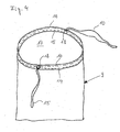
- the upper edge of the dirt bag 9 is for carrying out a cord-shaped Traction element 10 enclosed in a hose-like manner, which in particular from FIGS. 2 and 4 can be seen.
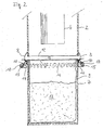
- Fig. 2 is the area of the separation chamber 7 and the vertical section housing 2 adjoining the top is clearly shown. You can see at first the lower edge 12 of the housing 2, in which the filter unit 6 is housed. Below the housing 2, the separation chamber 7 hangs over two open ones Latches 8 on the housing 2. Since the lids 8 are open, there is a small difference between the housing 2 and the separation chamber 7 clear gap 11, so that the clamping is released.
- the separation chamber 7 is loosely lined with the dirt bag 9 as it is 4 is shown in more detail.
- the dirt bag 9 that a plastic film or a cellulosic material that is either airtight or at least impermeable to fine dust particles.
- Below the bag 9 is tightly closed while it is at the top over its entire length Has the circumference of the opening 17.
- the edge of the bag 9 forming the opening 17 is hem-like to form a tubular guide and receptacle 14 edged, in which the tension elements 10 and 15 run parallel to each other.
- On the tubular receptacle has diametrically opposite points 14 passages 18 through which the tension elements 10 and 15 each over part of their length is done.
- the tension elements 10 and 15 form one closed loop each.
- the dirt bag 9 dresses the Separation chamber 7 completely and hangs with its upper edge over the upper edge 13 of the deposition chamber 7 down.
- the Dirt bag 9 already up to the intended filling level with dirt particles 16 filled.
- the two latches 8 are for removing the dirt bag 9 opened so that in the operating state still between the housing 2 and the Separation chamber 7 pinched edge of the dirt bag 9 is released.
- the dirt bag 9 is tied up.
- the separating chamber 6 can then be completely removed from the housing 2 uncoupled and the dirt bag 9 removed and disposed of.
- FIG. 3 An alternative to the embodiment of the invention shown in FIG. 2 is in FIG Fig. 3 shown.
- the same reference numerals are used for the same components 1, 2 and 4 used.
- the separation chamber 20 has two in its upper half diametrically opposite points openings 23 and is by means of two clamping screws 21 acting between housing 2 and separation chamber 20 firmly connected to the vacuum cleaner 1. By loosening the on the Clamping screws 21 seated wing nuts 22 can connect between Separation chamber 9 and housing 2 are solved.
- the separation chamber 20 is inside of the dirt bag 24 lined, which is filled up to about half with dirt particles 16.
- Attachment of the dirt bag 24 to the separation chamber 20 are at the top Edge of the dirt bag 24 adhesive tape 28 attached to the inside the deposition chamber 20 adhere.
- Around the top third of the dirt bag 24 is a tubular one extending over the entire circumference Recording 25 arranged at two diametrically opposite points Has openings 26. In turn, run in the tubular receptacle 25 the tensile elements 10 and 15, initially with part of their length by the Openings 26 out of the receptacle 25 and further out through the openings 23 the deposition chamber 20 are guided.
Landscapes
- Engineering & Computer Science (AREA)
- Mechanical Engineering (AREA)
- Filters For Electric Vacuum Cleaners (AREA)
- Electric Suction Cleaners (AREA)
- Cleaning Of Streets, Tracks, Or Beaches (AREA)
- Addition Polymer Or Copolymer, Post-Treatments, Or Chemical Modifications (AREA)
Abstract
Description
- Fig. 1
- eine Ansicht auf einen erfindungsgemäßen Zentralstaubsauger,
- Fig. 2
- einen vertikal geführten Teilschnitt durch den in Fig. 1 dargestellten Zentralstaubsauger im Bereich der Abscheidekammer,
- Fig. 3
- einen vertikal geführten Teilschnitt durch eine alternative Ausführungsform der Erfindung im Bereich der Abscheidekammer und
- Fig. 4
- eine Schrägansicht auf einen erfindungsgemäßen Schmutzbeutel.
Claims (15)
- Staubsauger, insbesondere Zentralstaubsauger (1), mit einer innerhalb eines Gehäuses (2) angeordneten Gebläseeinheit (3) zur Erzeugung einer Luftströmung und mit einer Abscheidekammer (7; 20), wobei die verunreinigte Luft (5) in den Staubsauger (1) geführt und mit hoher Geschwindigkeit einer Kreisbewegung unterworfen wird, wobei Schmutzpartikel (16) infolge der vorherrschenden Schwer- und Zentrifugalkräfte auf den Grund der Abscheidekammer (7; 20) absinken, dadurch gekennzeichnet, dass in der Abscheidekammer (7; 20) ein Schmutzbeutel (9; 24) zur Aufnahme der Schmutzpartikel (16) angeordnet ist, der über einen Schließmechanismus von außerhalb der Abscheidekammer (7; 20) verschließbar ist.
- Staubsauger nach Anspruch 1, dadurch gekennzeichnet, dass der Schließmechanismus zumindest ein Zugelement (10, 15) umfasst, das verschieblich gegenüber dem Schmutzbeutel (9; 24) verläuft, wobei das Zugelement (10, 15) verschieblich durch das Gehäuse (2) oder die Abscheidekammer (7; 20) oder zwischen Gehäuse (2) und Abscheidekammer (7; 20) nach außen geführt ist und bei Betätigung ein Verschnüren der Öffnung (17) des Schmutzbeutels (9; 24) bewirkt.
- Staubsauger nach Anspruch 2, dadurch gekennzeichnet, dass der Schmutzbeutel (9; 24) an seiner Außen- oder Innenfläche Führungen (14; 25) aufweist, in welchen das Zugelement (10, 15) gleitet.
- Staubsauger nach Anspruch 3, dadurch gekennzeichnet, dass die Führungen (14; 25) im Bereich der Öffnung (17) des Schmutzbeutels (9; 24) angeordnet sind.
- Staubsauger nach Anspruch 4, dadurch gekennzeichnet, dass die Führungen von Öffnungen im Schmutzbeutel (9; 24) oder von einer umlaufenden, schlauchförmigen Aufnahme (14; 25) gebildet sind.
- Staubsauger nach einem der Ansprüche 2 bis 5, dadurch gekennzeichnet, dass der Schießmechanismus zusätzlich ein zweites Zugelement (15) umfasst, das parallel zum ersten Zugglied (10) angeordnet ist und hinsichtlich dem ersten Zugelement (10) an der diametral gegenüberliegenden Stelle (23) aus der schlauchförmigen Aufnahme (14; 25) und/oder Abscheidekammer (7; 20) geführt ist.
- Staubsauger nach einem der Ansprüche 2 bis 6, dadurch gekennzeichnet, dass das Zugelemet (10, 15) aus einer Schnur, einem Draht oder Band besteht.
- Staubsauger nach einem der Ansprüche 1 bis 7, dadurch gekennzeichnet, dass die Abscheidekammer (7; 20) lösbar mit dem Gehäuse (2) des Staubsaugers (1) verbunden ist und der die Öffnung (17) des Schmutzbeutels (9; 24) bildende Rand zwischen Abscheidekammer (7; 20) und Gehäuse (2) eingeklemmt ist.
- Staubsauger nach Anspruch 8, dadurch gekennzeichnet, dass der Schließmechanismus außerhalb der Abscheidekammer (7; 20) angeordnet ist und zwischen dem Gehäuse (2) und dem Schmutzbeutel (9; 24) Befestigungsmittel (8; 21, 22) angeordnet sind, die ein stufenweises Lösen der Abscheidekammer (7; 20) vom Gehäuse (2) ermöglichen, in dem in der ersten Stufe zumindest die Klemmung aufgehoben wird.
- Staubsauger nach Anspruch 9, dadurch gekennzeichnet, dass die Befestigungsmittel einen Spannverschluss (8) oder eine Spannschraube (21, 22) umfassen.
- Staubsauger nach einem der Ansprüche 1 bis 10, dadurch gekennzeichnet, dass das oder die Zugelemente (10, 15) mit ihrem zur Betätigung des Schließmechanismus bestimmten Abschnitt an der Gebläseeinheit (3) befestigt sind, so dass mit dem Abnehmen der Abscheidekammer (7; 20) eine Verschnürung der Öffnung (17) des Schmutzbeutels (9; 24) erfolgt.
- Staubsauger nach Anspruch 11, dadurch gekennzeichnet, dass die Befestigung des oder der Zugelemente (10, 15) an der Gebläseeinheit (3) bei Erreichen einer vorbestimmten Zugkraft das oder die Zugelemente (10, 15) freigibt.
- Staubsauger nach Anspruch 11 oder 12, dadurch gekennzeichnet, dass die Befestigung nach Art einer Klemmbefestigung mit definierter Klemmkraft ausgebildet ist.
- Staubsauger nach einem der Ansprüche 11 bis 13, dadurch gekennzeichnet, dass das oder die Zugelemente (10, 15) eine Sollbruchstelle aufweisen.
- Staubsauger nach einem der Ansprüche 1 bis 14, dadurch gekennzeichnet, dass die Abscheidekammer (7; 20) oder der Schmutzbeutel (9; 24) Aussteifungselemente aufweist, die den Schmutzbeutel (9; 24) im Betriebszustand aufgeweitet halten.
Applications Claiming Priority (2)
| Application Number | Priority Date | Filing Date | Title |
|---|---|---|---|
| DE20300991U | 2003-01-23 | ||
| DE20300991U DE20300991U1 (de) | 2003-01-23 | 2003-01-23 | Staubsauger |
Publications (3)
| Publication Number | Publication Date |
|---|---|
| EP1440651A2 true EP1440651A2 (de) | 2004-07-28 |
| EP1440651A3 EP1440651A3 (de) | 2006-01-25 |
| EP1440651B1 EP1440651B1 (de) | 2010-12-29 |
Family
ID=7979331
Family Applications (1)
| Application Number | Title | Priority Date | Filing Date |
|---|---|---|---|
| EP04000935A Revoked EP1440651B1 (de) | 2003-01-23 | 2004-01-17 | Staubsauger |
Country Status (4)
| Country | Link |
|---|---|
| EP (1) | EP1440651B1 (de) |
| AT (1) | ATE493055T1 (de) |
| DE (2) | DE20300991U1 (de) |
| ES (1) | ES2358739T3 (de) |
Cited By (1)
| Publication number | Priority date | Publication date | Assignee | Title |
|---|---|---|---|---|
| US9149165B2 (en) | 2012-03-08 | 2015-10-06 | Bissell Homecare, Inc. | Vacuum cleaner and vacuum cleaner system |
Families Citing this family (1)
| Publication number | Priority date | Publication date | Assignee | Title |
|---|---|---|---|---|
| GB2523675B (en) * | 2015-04-27 | 2016-01-20 | Alan Graham Burr | Vacuum cleaner envelope |
Family Cites Families (9)
| Publication number | Priority date | Publication date | Assignee | Title |
|---|---|---|---|---|
| BE340238A (de) | 1926-02-15 | |||
| FR954306A (fr) | 1947-10-16 | 1949-12-22 | Perfectionnement au système filtrant des aspirateurs de poussières | |
| DE1948837U (de) | 1966-03-30 | 1966-11-03 | Siemens Elektrogeraete Gmbh | Schmutzbeutel fuer staubsauger. |
| DE8806673U1 (de) | 1988-05-20 | 1989-09-14 | Siemens Ag, 1000 Berlin Und 8000 Muenchen | Kesselstaubsauger |
| SE465949B (sv) * | 1990-10-01 | 1991-11-25 | Akp Tekno Oy | Centralenhet foer centraldammsugare |
| DE9110724U1 (de) | 1991-08-27 | 1991-11-07 | Schatzek, Ruth, 1000 Berlin | Wiederverschließbarer Staubbeutel für Staubsauger |
| SE508524C2 (sv) | 1997-02-13 | 1998-10-12 | Electrolux Ab | Anordning vid en cyklondammsugare |
| JPH11343003A (ja) * | 1998-06-02 | 1999-12-14 | Motoyoshi Togami | 袋 |
| US6178590B1 (en) * | 2000-03-20 | 2001-01-30 | Lindsay Manufacturing, Inc. | Vacuum cleaner cannister with removable bag |
-
2003
- 2003-01-23 DE DE20300991U patent/DE20300991U1/de not_active Expired - Lifetime
-
2004
- 2004-01-17 ES ES04000935T patent/ES2358739T3/es not_active Expired - Lifetime
- 2004-01-17 DE DE502004012037T patent/DE502004012037D1/de not_active Expired - Lifetime
- 2004-01-17 EP EP04000935A patent/EP1440651B1/de not_active Revoked
- 2004-01-17 AT AT04000935T patent/ATE493055T1/de active
Cited By (3)
| Publication number | Priority date | Publication date | Assignee | Title |
|---|---|---|---|---|
| US9149165B2 (en) | 2012-03-08 | 2015-10-06 | Bissell Homecare, Inc. | Vacuum cleaner and vacuum cleaner system |
| US9717380B2 (en) | 2012-03-08 | 2017-08-01 | Bissell Homecare, Inc. | Vacuum cleaner |
| US10398268B2 (en) | 2012-03-08 | 2019-09-03 | Bissell Homecare, Inc. | Vacuum cleaner |
Also Published As
| Publication number | Publication date |
|---|---|
| EP1440651A3 (de) | 2006-01-25 |
| DE502004012037D1 (de) | 2011-02-10 |
| ATE493055T1 (de) | 2011-01-15 |
| DE20300991U1 (de) | 2003-04-10 |
| EP1440651B1 (de) | 2010-12-29 |
| ES2358739T3 (es) | 2011-05-13 |
Similar Documents
| Publication | Publication Date | Title |
|---|---|---|
| DE10356156B4 (de) | Wirbelungs-Staubsammelvorrichtung eines Staubsaugers | |
| DE60320238T2 (de) | Vorrichtung für einen staubsauger | |
| DE102012211247B4 (de) | Kombination aus einem Kleinsauger und einem Staubsaugergehäuse sowie Kleinsauger und Staubsaugergehäuse | |
| DE102015105059B4 (de) | Filteranordnung, Haushaltsgerät mit einer Filteranordnung und Verfahren zum Wechseln eines Filters | |
| EP0209901A2 (de) | Schmutzsaugvorrichtung | |
| DE202010018085U1 (de) | Ein Reinigungsgerät | |
| DE60007266T2 (de) | Staubsauger | |
| DE102008011723B4 (de) | Staubsauger, insbesondere Haushalts-Staubsauger, sowie Verfahren zum Betreiben eines Staubsaugers | |
| DE2106058C3 (de) | Filter-Reinigungsvorrichtung für einen Staubsauger | |
| DE10021594A1 (de) | Staubbox | |
| DE102014113797B4 (de) | Abscheidebehälter für einen beutellosen Staubsauger | |
| DE3010130A1 (de) | Verfahren und geraet zum reinigen von gegenstaenden und raeumen | |
| EP0510056A1 (de) | Staubsauger. | |
| EP1440651B1 (de) | Staubsauger | |
| EP1930091B1 (de) | Absauggerät | |
| DE3408564A1 (de) | Staubsammelbehaeltnis fuer staubsauger | |
| DE3939645C3 (de) | Staubabscheider mit schlauchförmigen Filterelementen und Verfahren zum Wechseln derselben | |
| DE8910579U1 (de) | Filtersack | |
| DE3843094A1 (de) | Vorrichtung zum separieren schwerer objekte in einem staubsauger | |
| DE3540688A1 (de) | Entstaubungsvorrichtung fuer textilmaschinen und maschinenraeume | |
| DE3501948A1 (de) | Staubfiltervorrichtung | |
| EP4176789B1 (de) | Filtereinheit zum einbau in eine staubsaugvorrichtung sowie staubsaugvorrichtung mit filtereinheit | |
| DE20110263U1 (de) | Vorrichtung zum Abfangen von Gegenständen aus dem Luftstrom eines Staubsaugers | |
| DE102018112752A1 (de) | Staubabscheider für Staubsauger und Staubsauger | |
| DE20306763U1 (de) | Vorsatzeinrichtung zum Ansetzen an die Ansaugöffnung eines Haus-Staubsaugers |
Legal Events
| Date | Code | Title | Description |
|---|---|---|---|
| PUAI | Public reference made under article 153(3) epc to a published international application that has entered the european phase |
Free format text: ORIGINAL CODE: 0009012 |
|
| AK | Designated contracting states |
Kind code of ref document: A2 Designated state(s): AT BE BG CH CY CZ DE DK EE ES FI FR GB GR HU IE IT LI LU MC NL PT RO SE SI SK TR |
|
| AX | Request for extension of the european patent |
Extension state: AL LT LV MK |
|
| PUAL | Search report despatched |
Free format text: ORIGINAL CODE: 0009013 |
|
| AK | Designated contracting states |
Kind code of ref document: A3 Designated state(s): AT BE BG CH CY CZ DE DK EE ES FI FR GB GR HU IE IT LI LU MC NL PT RO SE SI SK TR |
|
| AX | Request for extension of the european patent |
Extension state: AL LT LV MK |
|
| 17P | Request for examination filed |
Effective date: 20060601 |
|
| AKX | Designation fees paid |
Designated state(s): AT BE BG CH CY CZ DE DK EE ES FI FR GB GR HU IE IT LI LU MC NL PT RO SE SI SK TR |
|
| 17Q | First examination report despatched |
Effective date: 20071023 |
|
| GRAP | Despatch of communication of intention to grant a patent |
Free format text: ORIGINAL CODE: EPIDOSNIGR1 |
|
| GRAS | Grant fee paid |
Free format text: ORIGINAL CODE: EPIDOSNIGR3 |
|
| GRAA | (expected) grant |
Free format text: ORIGINAL CODE: 0009210 |
|
| AK | Designated contracting states |
Kind code of ref document: B1 Designated state(s): AT BE BG CH CY CZ DE DK EE ES FI FR GB GR HU IE IT LI LU MC NL PT RO SE SI SK TR |
|
| REG | Reference to a national code |
Ref country code: GB Ref legal event code: FG4D Free format text: NOT ENGLISH |
|
| REG | Reference to a national code |
Ref country code: CH Ref legal event code: EP |
|
| REG | Reference to a national code |
Ref country code: IE Ref legal event code: FG4D Free format text: LANGUAGE OF EP DOCUMENT: GERMAN |
|
| REF | Corresponds to: |
Ref document number: 502004012037 Country of ref document: DE Date of ref document: 20110210 Kind code of ref document: P |
|
| REG | Reference to a national code |
Ref country code: DE Ref legal event code: R096 Ref document number: 502004012037 Country of ref document: DE Effective date: 20110210 |
|
| REG | Reference to a national code |
Ref country code: CH Ref legal event code: NV Representative=s name: PATENTANWAELTE SCHAAD, BALASS, MENZL & PARTNER AG |
|
| REG | Reference to a national code |
Ref country code: NL Ref legal event code: T3 |
|
| REG | Reference to a national code |
Ref country code: ES Ref legal event code: FG2A Ref document number: 2358739 Country of ref document: ES Kind code of ref document: T3 Effective date: 20110503 |
|
| PG25 | Lapsed in a contracting state [announced via postgrant information from national office to epo] |
Ref country code: SI Free format text: LAPSE BECAUSE OF FAILURE TO SUBMIT A TRANSLATION OF THE DESCRIPTION OR TO PAY THE FEE WITHIN THE PRESCRIBED TIME-LIMIT Effective date: 20101229 Ref country code: CY Free format text: LAPSE BECAUSE OF FAILURE TO SUBMIT A TRANSLATION OF THE DESCRIPTION OR TO PAY THE FEE WITHIN THE PRESCRIBED TIME-LIMIT Effective date: 20101229 Ref country code: FI Free format text: LAPSE BECAUSE OF FAILURE TO SUBMIT A TRANSLATION OF THE DESCRIPTION OR TO PAY THE FEE WITHIN THE PRESCRIBED TIME-LIMIT Effective date: 20101229 Ref country code: BG Free format text: LAPSE BECAUSE OF FAILURE TO SUBMIT A TRANSLATION OF THE DESCRIPTION OR TO PAY THE FEE WITHIN THE PRESCRIBED TIME-LIMIT Effective date: 20110329 Ref country code: SE Free format text: LAPSE BECAUSE OF FAILURE TO SUBMIT A TRANSLATION OF THE DESCRIPTION OR TO PAY THE FEE WITHIN THE PRESCRIBED TIME-LIMIT Effective date: 20101229 |
|
| PG25 | Lapsed in a contracting state [announced via postgrant information from national office to epo] |
Ref country code: GR Free format text: LAPSE BECAUSE OF FAILURE TO SUBMIT A TRANSLATION OF THE DESCRIPTION OR TO PAY THE FEE WITHIN THE PRESCRIBED TIME-LIMIT Effective date: 20110330 Ref country code: PT Free format text: LAPSE BECAUSE OF FAILURE TO SUBMIT A TRANSLATION OF THE DESCRIPTION OR TO PAY THE FEE WITHIN THE PRESCRIBED TIME-LIMIT Effective date: 20110429 Ref country code: CZ Free format text: LAPSE BECAUSE OF FAILURE TO SUBMIT A TRANSLATION OF THE DESCRIPTION OR TO PAY THE FEE WITHIN THE PRESCRIBED TIME-LIMIT Effective date: 20101229 Ref country code: EE Free format text: LAPSE BECAUSE OF FAILURE TO SUBMIT A TRANSLATION OF THE DESCRIPTION OR TO PAY THE FEE WITHIN THE PRESCRIBED TIME-LIMIT Effective date: 20101229 |
|
| PG25 | Lapsed in a contracting state [announced via postgrant information from national office to epo] |
Ref country code: RO Free format text: LAPSE BECAUSE OF FAILURE TO SUBMIT A TRANSLATION OF THE DESCRIPTION OR TO PAY THE FEE WITHIN THE PRESCRIBED TIME-LIMIT Effective date: 20101229 Ref country code: SK Free format text: LAPSE BECAUSE OF FAILURE TO SUBMIT A TRANSLATION OF THE DESCRIPTION OR TO PAY THE FEE WITHIN THE PRESCRIBED TIME-LIMIT Effective date: 20101229 Ref country code: MC Free format text: LAPSE BECAUSE OF NON-PAYMENT OF DUE FEES Effective date: 20110131 |
|
| PLBI | Opposition filed |
Free format text: ORIGINAL CODE: 0009260 |
|
| PG25 | Lapsed in a contracting state [announced via postgrant information from national office to epo] |
Ref country code: DK Free format text: LAPSE BECAUSE OF FAILURE TO SUBMIT A TRANSLATION OF THE DESCRIPTION OR TO PAY THE FEE WITHIN THE PRESCRIBED TIME-LIMIT Effective date: 20101229 |
|
| PLAX | Notice of opposition and request to file observation + time limit sent |
Free format text: ORIGINAL CODE: EPIDOSNOBS2 |
|
| 26 | Opposition filed |
Opponent name: ALFRED KAERCHER GMBH & CO. KG Effective date: 20110926 |
|
| REG | Reference to a national code |
Ref country code: DE Ref legal event code: R026 Ref document number: 502004012037 Country of ref document: DE Effective date: 20110926 |
|
| PLAF | Information modified related to communication of a notice of opposition and request to file observations + time limit |
Free format text: ORIGINAL CODE: EPIDOSCOBS2 |
|
| PLBB | Reply of patent proprietor to notice(s) of opposition received |
Free format text: ORIGINAL CODE: EPIDOSNOBS3 |
|
| PGFP | Annual fee paid to national office [announced via postgrant information from national office to epo] |
Ref country code: IT Payment date: 20120125 Year of fee payment: 9 |
|
| PLBP | Opposition withdrawn |
Free format text: ORIGINAL CODE: 0009264 |
|
| PGFP | Annual fee paid to national office [announced via postgrant information from national office to epo] |
Ref country code: GB Payment date: 20130122 Year of fee payment: 10 Ref country code: FR Payment date: 20130207 Year of fee payment: 10 Ref country code: CH Payment date: 20130123 Year of fee payment: 10 Ref country code: DE Payment date: 20130124 Year of fee payment: 10 Ref country code: IE Payment date: 20130121 Year of fee payment: 10 Ref country code: ES Payment date: 20130122 Year of fee payment: 10 |
|
| PG25 | Lapsed in a contracting state [announced via postgrant information from national office to epo] |
Ref country code: LU Free format text: LAPSE BECAUSE OF NON-PAYMENT OF DUE FEES Effective date: 20110117 |
|
| PGFP | Annual fee paid to national office [announced via postgrant information from national office to epo] |
Ref country code: NL Payment date: 20130121 Year of fee payment: 10 Ref country code: BE Payment date: 20130121 Year of fee payment: 10 |
|
| PGFP | Annual fee paid to national office [announced via postgrant information from national office to epo] |
Ref country code: AT Payment date: 20130121 Year of fee payment: 10 |
|
| PG25 | Lapsed in a contracting state [announced via postgrant information from national office to epo] |
Ref country code: TR Free format text: LAPSE BECAUSE OF FAILURE TO SUBMIT A TRANSLATION OF THE DESCRIPTION OR TO PAY THE FEE WITHIN THE PRESCRIBED TIME-LIMIT Effective date: 20101229 |
|
| PG25 | Lapsed in a contracting state [announced via postgrant information from national office to epo] |
Ref country code: HU Free format text: LAPSE BECAUSE OF FAILURE TO SUBMIT A TRANSLATION OF THE DESCRIPTION OR TO PAY THE FEE WITHIN THE PRESCRIBED TIME-LIMIT Effective date: 20101229 |
|
| RDAF | Communication despatched that patent is revoked |
Free format text: ORIGINAL CODE: EPIDOSNREV1 |
|
| BERE | Be: lapsed |
Owner name: ZSA VERTRIEBS G.M.B.H. ZENTRALE STAUBSAUGER-ANLAGE Effective date: 20140131 |
|
| REG | Reference to a national code |
Ref country code: DE Ref legal event code: R119 Ref document number: 502004012037 Country of ref document: DE |
|
| REG | Reference to a national code |
Ref country code: NL Ref legal event code: V1 Effective date: 20140801 |
|
| REG | Reference to a national code |
Ref country code: CH Ref legal event code: PL |
|
| REG | Reference to a national code |
Ref country code: AT Ref legal event code: MM01 Ref document number: 493055 Country of ref document: AT Kind code of ref document: T Effective date: 20140117 |
|
| GBPC | Gb: european patent ceased through non-payment of renewal fee |
Effective date: 20140117 |
|
| RDAG | Patent revoked |
Free format text: ORIGINAL CODE: 0009271 |
|
| STAA | Information on the status of an ep patent application or granted ep patent |
Free format text: STATUS: PATENT REVOKED |
|
| REG | Reference to a national code |
Ref country code: DE Ref legal event code: R119 Ref document number: 502004012037 Country of ref document: DE Effective date: 20140801 |
|
| PG25 | Lapsed in a contracting state [announced via postgrant information from national office to epo] |
Ref country code: LI Free format text: LAPSE BECAUSE OF NON-PAYMENT OF DUE FEES Effective date: 20140131 Ref country code: CH Free format text: LAPSE BECAUSE OF NON-PAYMENT OF DUE FEES Effective date: 20140131 |
|
| REG | Reference to a national code |
Ref country code: FR Ref legal event code: ST Effective date: 20140930 |
|
| REG | Reference to a national code |
Ref country code: IE Ref legal event code: MM4A |
|
| 27W | Patent revoked |
Effective date: 20140714 |
|
| PG25 | Lapsed in a contracting state [announced via postgrant information from national office to epo] |
Ref country code: FR Free format text: LAPSE BECAUSE OF NON-PAYMENT OF DUE FEES Effective date: 20140131 Ref country code: GB Free format text: LAPSE BECAUSE OF NON-PAYMENT OF DUE FEES Effective date: 20140117 Ref country code: AT Free format text: LAPSE BECAUSE OF NON-PAYMENT OF DUE FEES Effective date: 20140117 |
|
| PG25 | Lapsed in a contracting state [announced via postgrant information from national office to epo] |
Ref country code: BE Free format text: LAPSE BECAUSE OF NON-PAYMENT OF DUE FEES Effective date: 20140131 |
|
| REG | Reference to a national code |
Ref country code: AT Ref legal event code: MA03 Ref document number: 493055 Country of ref document: AT Kind code of ref document: T Effective date: 20140714 |
|
| PG25 | Lapsed in a contracting state [announced via postgrant information from national office to epo] |
Ref country code: IT Free format text: LAPSE BECAUSE OF NON-PAYMENT OF DUE FEES Effective date: 20140117 |
|
| PG25 | Lapsed in a contracting state [announced via postgrant information from national office to epo] |
Ref country code: ES Free format text: LAPSE BECAUSE OF NON-PAYMENT OF DUE FEES Effective date: 20140118 |