EP1439037A2 - Elektrohandwerkzeugmaschine mit kontaktlosem elektrischen Handschalter - Google Patents
Elektrohandwerkzeugmaschine mit kontaktlosem elektrischen Handschalter Download PDFInfo
- Publication number
- EP1439037A2 EP1439037A2 EP20030104755 EP03104755A EP1439037A2 EP 1439037 A2 EP1439037 A2 EP 1439037A2 EP 20030104755 EP20030104755 EP 20030104755 EP 03104755 A EP03104755 A EP 03104755A EP 1439037 A2 EP1439037 A2 EP 1439037A2
- Authority
- EP
- European Patent Office
- Prior art keywords
- electric hand
- sensor switch
- machine tool
- hand machine
- switching means
- Prior art date
- Legal status (The legal status is an assumption and is not a legal conclusion. Google has not performed a legal analysis and makes no representation as to the accuracy of the status listed.)
- Granted
Links
Images

Classifications
-
- B—PERFORMING OPERATIONS; TRANSPORTING
- B25—HAND TOOLS; PORTABLE POWER-DRIVEN TOOLS; MANIPULATORS
- B25F—COMBINATION OR MULTI-PURPOSE TOOLS NOT OTHERWISE PROVIDED FOR; DETAILS OR COMPONENTS OF PORTABLE POWER-DRIVEN TOOLS NOT PARTICULARLY RELATED TO THE OPERATIONS PERFORMED AND NOT OTHERWISE PROVIDED FOR
- B25F5/00—Details or components of portable power-driven tools not particularly related to the operations performed and not otherwise provided for
- B25F5/006—Vibration damping means
-
- H—ELECTRICITY
- H01—ELECTRIC ELEMENTS
- H01H—ELECTRIC SWITCHES; RELAYS; SELECTORS; EMERGENCY PROTECTIVE DEVICES
- H01H36/00—Switches actuated by change of magnetic field or of electric field, e.g. by change of relative position of magnet and switch, by shielding
-
- H—ELECTRICITY
- H01—ELECTRIC ELEMENTS
- H01H—ELECTRIC SWITCHES; RELAYS; SELECTORS; EMERGENCY PROTECTIVE DEVICES
- H01H9/00—Details of switching devices, not covered by groups H01H1/00 - H01H7/00
- H01H9/02—Bases, casings, or covers
- H01H9/06—Casing of switch constituted by a handle serving a purpose other than the actuation of the switch, e.g. by the handle of a vacuum cleaner
-
- H—ELECTRICITY
- H03—ELECTRONIC CIRCUITRY
- H03K—PULSE TECHNIQUE
- H03K17/00—Electronic switching or gating, i.e. not by contact-making and –breaking
- H03K17/94—Electronic switching or gating, i.e. not by contact-making and –breaking characterised by the way in which the control signals are generated
- H03K17/965—Switches controlled by moving an element forming part of the switch
- H03K17/97—Switches controlled by moving an element forming part of the switch using a magnetic movable element
Definitions
- the invention relates to an electric hand machine tool with a contactless electric hand switch, especially an at least partially striking Chisel hammer or combination hammer.
- an electric hand machine tool is a hand switch controlled, the actuating means mechanically piezo sensors for controlling a Circuit breaker actuated.
- the pressure sensors are necessarily with the Actuators in mechanical contact, causing vibrations on the actuators are transferable.
- a combination hammer with a contactless electrical Hand switch one, the actuating means directly, according to DE19942156 Switching linkage controllably assigned, contactless electrical Hall sensor switch on, which is connected to the actuating means in a vibration-free manner via the housing. To the sensor switch must be connected to the housing.
- the object of the invention is to implement a technologically simple, contactless electric hand switch, the sensor switch with respect to the Actuator is insensitive to vibration.
- an electric hand machine tool has one along one Vibrating axis vibrating assembly with a contactless electrical hand switch an actuator and a sensor switch, the sensor switch is connected vibration-free to an at least pivotable switching means carrier, the Swivel axis is oriented along the vibration axis and which over a along the Axis of vibration limits axially movable pivot transmission means from Actuating means is manually controllable.
- the switching means carrier advantageously forms one with the actuating means Rotary swivel clutch, further advantageously in the form of an axially from the switching medium carrier eccentrically cantilevered coupling pins, which are in a coupling guide of the Actuating means engages, whereby the contactless electric hand switch with an in The housing of the electric hand-held power tool can only be moved with the actuating means the final assembly is assembled.
- a corresponding geometry of the clutch guide advantageously takes place Movement transformation between the actuating means and the switching means carrier, whereby, for example, with a clutch guide in the form of a guide slot a transverse to Slide switch that can be displaced by the vibration axis can be easily implemented.
- the sensor switch is advantageously connected to the vibrating assembly, further advantageously cast directly into an engine control electronics, which makes the sensor switch is an integral part of vibration-insensitive engine control electronics, which optionally contributes to the vibration mass of the vibrating assembly.
- the switching means carrier is advantageous as a swivel rocker that can be pivoted to a limited extent on both sides formed, whereby a switching means spaced transversely to the pivot axis only within a circular arc area delimited by two end positions is displaceable Switch positions are assignable.
- the switching means carrier is advantageous with respect to the sensor switch in at least one Switching position stable, further advantageous in exactly two switching positions bistable, elastic preloaded, making the switch positions insensitive to vibration.
- a leaf spring is advantageous between the switching medium carrier and the sensor switch Preload of the switching position arranged, which is technologically easy to manufacture.
- the switching means as a permanent magnet and the sensor switch as a Hall sensor switch are advantageous which are insensitive to dust.
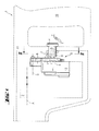
- a striking electric hand-held machine tool 1 is only indicated an assembly 2 vibrating along a vibration axis A, a contactless one electric hand switch 3 with an actuating means 4 and a sensor switch 5.
- the sensor switch 5 is vibration-free with a pivotable switching means carrier 6 connected, whose pivot axis S is oriented parallel to the vibration axis A.
- the switching means carrier 6 can be pivoted to a limited extent on both sides Swivel rocker with a switching means 13 spaced apart transversely to the swivel axis S in the form two anti-parallel oriented permanent magnets.
- the switching medium carrier 6 is with respect to the sensor switch 5 via a leaf spring 14 in both switching positions ON / OFF bistable elastic pre-tensioned.
- the switching means carrier is through end stops 15a, 15b only within a limit defined by the two assigned end positions I, II Circular arc area X compared to the differential Hall sensor switch Sensor switch 5 displaceable, which in a potting compound 16 of the motor control 12 is poured.
Landscapes
- Engineering & Computer Science (AREA)
- Mechanical Engineering (AREA)
- Percussive Tools And Related Accessories (AREA)
- Portable Power Tools In General (AREA)
- Mechanisms For Operating Contacts (AREA)
Abstract
Description
- Fig. 1
- als Ausschnitt einer vibrierenden Elektrohandwerkzeugmaschine
- Fig. 2
- als Einzelheit des kontaktlosen Handschalters, gesehen entsprechend Linie II-II auf Fig. 1
Claims (8)
- Elektrohandwerkzeugmaschine mit einer längs einer Vibrationsachse (A) vibrierenden Baugruppe (2), einem kontaktlosen elektrischen Handschalter (3) mit einem Betätigungsmittel (4) und einem Sensorschalter (5), dadurch gekennzeichnet, dass der Sensorschalter (5) vibrationsfrei mit einem zumindest schwenkbaren Schaltmittelträger (6) verbunden ist, dessen Schwenkachse (S) längs der Vibrationsachse (A) orientiert ist und welcher über ein längs der Vibrationsachse (A) begrenzt axial bewegliches Schwenkübertragungsmittel (7) vom Betätigungsmittel (4) händisch steuerbar ist.
- Elektrohandwerkzeugmaschine nach Anspruch 1, dadurch gekennzeichnet, dass der Schaltmittelträger (6) mit dem Betätigungsmittel (4) eine Drehschwenkkupplung (7) ausbildet, optional in Form eines aus dem Schaltmittelträger (6) axial exzentrisch auskragenden Kupplungspins (8), der in eine Kupplungsführung (9) des Betätigungsmittels (4) eingreift.
- Elektrohandwerkzeugmaschine nach Anspruch 1 oder 2, dadurch gekennzeichnet, dass durch eine entsprechende Geometrie der Kupplungsführung (9) eine Bewegungstransformation zwischen dem Betätigungsmittel (4) und dem Schaltmittelträger (6) erfolgt.
- Elektrohandwerkzeugmaschine nach einem der Ansprüche 1 bis 3, dadurch gekennzeichnet, dass der Sensorschalter (5) mit der vibrierenden Baugruppe (2) verbunden ist, optional direkt in einer Motorsteuerelektronik (12) eingegossen ist.
- Elektrohandwerkzeugmaschine nach einem der vorherigen Ansprüche, dadurch gekennzeichnet, dass der Schaltmittelträger (6) als beidseitig begrenzt drehschwenkbare Schwenkwippe ausgebildet ist.
- Elektrohandwerkzeugmaschine nach einem der vorherigen Ansprüche, dadurch gekennzeichnet, dass der Schaltmittelträger (6) bezüglich des Sensorschalters (5) in zumindest einer Schaltposition stabil ist, optional in genau zwei Schaltpositionen bistabil.
- Elektrohandwerkzeugmaschine nach Anspruch 6, dadurch gekennzeichnet, dass zwischen dem Schaltmittelträger (6) und dem Sensorschalter (5) eine Blattfeder (14) zur Vorspannung der Schaltposition angeordnet ist.
- Elektrohandwerkzeugmaschine nach einem der vorherigen Ansprüche, dadurch gekennzeichnet, dass das Schaltmittel (13) als Permanentmagnet und der Sensorschalter (5) als Hall- Sensorschalter ausgeführt ist.
Applications Claiming Priority (2)
| Application Number | Priority Date | Filing Date | Title |
|---|---|---|---|
| DE10259569A DE10259569A1 (de) | 2002-12-19 | 2002-12-19 | Elektrohandwerkzeugmaschine mit kontaktlosem elektrischen Handschalter |
| DE10259569 | 2002-12-19 |
Publications (3)
| Publication Number | Publication Date |
|---|---|
| EP1439037A2 true EP1439037A2 (de) | 2004-07-21 |
| EP1439037A3 EP1439037A3 (de) | 2009-09-30 |
| EP1439037B1 EP1439037B1 (de) | 2015-07-01 |
Family
ID=32403980
Family Applications (1)
| Application Number | Title | Priority Date | Filing Date |
|---|---|---|---|
| EP03104755.8A Expired - Lifetime EP1439037B1 (de) | 2002-12-19 | 2003-12-17 | Elektrohandwerkzeugmaschine mit kontaktlosem elektrischen Handschalter |
Country Status (7)
| Country | Link |
|---|---|
| US (2) | US20040206519A1 (de) |
| EP (1) | EP1439037B1 (de) |
| JP (1) | JP4532103B2 (de) |
| CN (1) | CN100563943C (de) |
| DE (1) | DE10259569A1 (de) |
| ES (1) | ES2546279T3 (de) |
| PL (1) | PL206411B1 (de) |
Cited By (1)
| Publication number | Priority date | Publication date | Assignee | Title |
|---|---|---|---|---|
| EP1788597A1 (de) * | 2005-11-16 | 2007-05-23 | Marquardt GmbH | Elektrowerkzeug, insbesondere Akku-Elektrowerkzeug |
Families Citing this family (25)
| Publication number | Priority date | Publication date | Assignee | Title |
|---|---|---|---|---|
| US7086111B2 (en) * | 2001-03-16 | 2006-08-08 | Braun Gmbh | Electric dental cleaning device |
| DK1367958T3 (da) * | 2001-03-14 | 2008-01-28 | Braun Gmbh | Anordning til tandrensning |
| DE10159395B4 (de) * | 2001-12-04 | 2010-11-11 | Braun Gmbh | Vorrichtung zur Zahnreinigung |
| US8443476B2 (en) | 2001-12-04 | 2013-05-21 | Braun Gmbh | Dental cleaning device |
| DE102004062150A1 (de) * | 2004-12-23 | 2006-07-13 | Braun Gmbh | Auswechselbares Zubehörteil für ein Elektrokleingerät und Verfahren zum Bestimmen der Benutzungsdauer des Zubehörteils |
| TWM301108U (en) * | 2006-05-19 | 2006-11-21 | Tranmax Machinery Co Ltd | Structure of pneumatic spanner which is well-operated by single-hand to control CW or CCW direction |
| DE102006040647A1 (de) * | 2006-08-30 | 2008-03-13 | Robert Bosch Gmbh | Handwerkzeugmaschine |
| DE102008003246B4 (de) | 2007-01-13 | 2023-09-21 | Marquardt Gmbh | Ansteuereinrichtung für einen Elektromotor |
| DE102007022827A1 (de) * | 2007-05-15 | 2008-11-20 | Braun Gmbh | Zahnbürstenaufsatzteil sowie Verfahren zu seiner Herstellung |
| US7820931B2 (en) * | 2007-07-25 | 2010-10-26 | Symbol Technologies, Inc. | Trigger arrangement with feedback response |
| DE102007000454A1 (de) * | 2007-11-09 | 2009-05-14 | Hilti Aktiengesellschaft | Schlagende Handwerkzeugmaschine mit kontaktlosen Handschalter im Seitenhandgriff |
| JP5180697B2 (ja) * | 2008-06-19 | 2013-04-10 | 株式会社マキタ | 手持式作業工具 |
| DE102010023397A1 (de) * | 2010-06-10 | 2011-12-15 | Festool Gmbh | Hand-Werkzeugmaschine mit einem elektrischen Schalter |
| EP2420203B1 (de) | 2010-08-19 | 2019-10-23 | Braun GmbH | Resonanzmotoreinheit und Elektrogerät mit Resonanzmotoreinheit |
| EP3090838B1 (de) | 2011-05-19 | 2020-06-17 | Black & Decker Inc. | Elektrowerkzeug mit kraftsensorelektrokupplung |
| CN103703668B (zh) | 2011-07-25 | 2016-12-07 | 博朗有限公司 | 线性电动聚合物马达和具有所述线性电动聚合物马达的装置 |
| EP2550938B1 (de) | 2011-07-25 | 2015-01-14 | Braun GmbH | Mundpflegevorrichtung |
| EP2550937B1 (de) | 2011-07-25 | 2014-02-26 | Braun GmbH | Magnetische Verbindung zwischen einem Zahnbürstengriff und einem Bürstenkopf |
| DE102012221748A1 (de) * | 2012-11-28 | 2014-05-28 | Robert Bosch Gmbh | Handwerkzeugmaschine |
| WO2020231974A1 (en) | 2019-05-13 | 2020-11-19 | Milwaukee Electric Tool Corporation | Contactless trigger with rotational magnetic sensor for a power tool |
| EP3822031A1 (de) * | 2019-11-14 | 2021-05-19 | Hilti Aktiengesellschaft | Verfahren zum steuern und regeln einer werkzeugmaschine |
| DE112021003305T5 (de) * | 2020-07-10 | 2023-04-20 | Makita Corporation | Arbeitswerkzeug und elektrisches werkzeug |
| CN114868513A (zh) | 2021-02-05 | 2022-08-09 | 米沃奇电动工具公司 | 用于割草机的非接触开关 |
| US12587195B2 (en) | 2021-03-04 | 2026-03-24 | Snap-On Incorporated | Non-contact direction selector mechanism |
| DE102024102589A1 (de) * | 2023-02-08 | 2024-08-08 | Husqvarna Ab | Handgehaltenes angetriebenes Werkzeug |
Citations (3)
| Publication number | Priority date | Publication date | Assignee | Title |
|---|---|---|---|---|
| US5014793A (en) | 1989-04-10 | 1991-05-14 | Measurement Specialties, Inc. | Variable speed DC motor controller apparatus particularly adapted for control of portable-power tools |
| DE4401664A1 (de) | 1994-01-21 | 1995-07-27 | Bosch Gmbh Robert | Bohrhammer |
| DE19942156A1 (de) | 1999-09-03 | 2001-03-08 | Hilti Ag | Umschalteinrichtung für multifunktionale handgeführte Werkzeugmaschinen |
Family Cites Families (30)
| Publication number | Priority date | Publication date | Assignee | Title |
|---|---|---|---|---|
| US2539930A (en) * | 1947-04-07 | 1951-01-30 | Girard Mfg Products Inc | Power-driven tool |
| US3085169A (en) * | 1960-02-24 | 1963-04-09 | Diehl Mfg Co | Speed-setting indicators for portable electric tools |
| NL129505C (de) * | 1966-07-13 | |||
| US3742364A (en) * | 1971-10-22 | 1973-06-26 | Lucerne Products Inc | Reversing switch lever |
| US3932830A (en) * | 1975-01-23 | 1976-01-13 | White-Westinghouse Corporation | Push-to-turn thermal cycling switch |
| US4137512A (en) * | 1977-05-13 | 1979-01-30 | Illinois Tool Works Inc. | Contactless magnetic switch |
| US4256358A (en) * | 1979-12-03 | 1981-03-17 | Illinois Tool Works Inc. | Wire engagement and release arrangement |
| US4262181A (en) * | 1980-04-21 | 1981-04-14 | Leviton Manufacturing Company, Inc. | Snap-in switch housing |
| US4348603A (en) * | 1981-01-29 | 1982-09-07 | Black & Decker Inc. | Printed-circuit board and trigger-switch arrangement for a portable electric tool |
| US4574471A (en) * | 1983-03-31 | 1986-03-11 | Black & Decker Inc. | Methods of assembling components of an electric motor |
| AT386489B (de) * | 1984-06-15 | 1988-08-25 | Electrovac | Thermischer schalter mit einem aus einer thermobimetallschnappscheibe gebildeten temperaturfuehler |
| DE3443670A1 (de) * | 1984-11-30 | 1986-06-05 | C. & E. Fein Gmbh & Co, 7000 Stuttgart | Kraftgetriebene schraubvorrichtung mit variabler drehmomenteinstellung |
| EP0308566B1 (de) * | 1987-09-23 | 1992-12-16 | MANNESMANN Aktiengesellschaft | Büromaschine, insbesondere Matrixdrucker, mit Druckkopf/Schreibwiderlager-Abstandsjustage |
| US4857681A (en) * | 1987-10-14 | 1989-08-15 | Aircap Industries Corp. | Dead man-type electrical control device for power tools |
| US4998589A (en) * | 1990-02-26 | 1991-03-12 | Wiesendanger John A | Variable speed drill control cam apparatus |
| CN2069181U (zh) * | 1990-05-02 | 1991-01-09 | 邵正贤 | 电动工具无触点无级调速开关 |
| US5365155A (en) * | 1990-10-22 | 1994-11-15 | Marquardt Gmbh | Rotational speed control and use of same to control the rotational speed of an electric hand tool motor |
| DE4038786A1 (de) * | 1990-12-05 | 1992-06-11 | Bsg Schalttechnik | Vorrichtung zur steuerung oder regelung von durch akkus versorgter geraete |
| US5561734A (en) * | 1992-08-13 | 1996-10-01 | Milwaukee Electric Tool Corporation | Dial speed control for hand-held power tool |
| US5414793A (en) * | 1993-04-27 | 1995-05-09 | Ryobi Motor Products Corp. | Speed control mechanism for a power tool |
| US5867082A (en) * | 1995-06-02 | 1999-02-02 | Duraswitch, Inc. | Switch with magnetically-coupled armature |
| CH692658A5 (de) * | 1996-06-15 | 2002-09-13 | Bosch Gmbh Robert | Elektrokombihammer. |
| DE19736454B4 (de) * | 1997-08-21 | 2005-01-27 | Infineon Technologies Ag | Kontaktloser Näherungsschalter |
| US5943917A (en) * | 1997-10-16 | 1999-08-31 | Honeywell Inc. | Thermostat having a temperature setting lever with tactilely determinable position |
| DE19756857C1 (de) * | 1997-12-19 | 1999-07-08 | Wacker Werke Kg | Stell- und/oder Regeleinrichtung für handgehaltene Elektrowerkzeuge |
| US5955802A (en) * | 1997-12-19 | 1999-09-21 | Black & Decker Inc. | Reversing mechanism for electric motors |
| DE19909854A1 (de) * | 1998-03-11 | 1999-09-16 | Marquardt Gmbh | Elektrischer Schalter |
| DE19942157A1 (de) * | 1999-09-03 | 2001-03-08 | Hilti Ag | EIN/AUS-Schalt- oder Drehzahleinstelleinrichtung für Elektrowerkzeuge |
| DE10137159A1 (de) * | 2001-07-30 | 2003-02-20 | Hilti Ag | Schlagendes Elektrohandwerkzeuggerät |
| US6729016B2 (en) * | 2001-10-05 | 2004-05-04 | Honeywell International Inc. | Method for making a modular reed switch assembly |
-
2002
- 2002-12-19 DE DE10259569A patent/DE10259569A1/de not_active Withdrawn
-
2003
- 2003-12-17 EP EP03104755.8A patent/EP1439037B1/de not_active Expired - Lifetime
- 2003-12-17 ES ES03104755.8T patent/ES2546279T3/es not_active Expired - Lifetime
- 2003-12-18 PL PL364132A patent/PL206411B1/pl unknown
- 2003-12-18 CN CNB200310120693XA patent/CN100563943C/zh not_active Expired - Fee Related
- 2003-12-18 US US10/740,195 patent/US20040206519A1/en not_active Abandoned
- 2003-12-19 JP JP2003422324A patent/JP4532103B2/ja not_active Expired - Fee Related
-
2005
- 2005-11-22 US US11/286,039 patent/US7174972B2/en not_active Expired - Lifetime
Patent Citations (3)
| Publication number | Priority date | Publication date | Assignee | Title |
|---|---|---|---|---|
| US5014793A (en) | 1989-04-10 | 1991-05-14 | Measurement Specialties, Inc. | Variable speed DC motor controller apparatus particularly adapted for control of portable-power tools |
| DE4401664A1 (de) | 1994-01-21 | 1995-07-27 | Bosch Gmbh Robert | Bohrhammer |
| DE19942156A1 (de) | 1999-09-03 | 2001-03-08 | Hilti Ag | Umschalteinrichtung für multifunktionale handgeführte Werkzeugmaschinen |
Cited By (1)
| Publication number | Priority date | Publication date | Assignee | Title |
|---|---|---|---|---|
| EP1788597A1 (de) * | 2005-11-16 | 2007-05-23 | Marquardt GmbH | Elektrowerkzeug, insbesondere Akku-Elektrowerkzeug |
Also Published As
| Publication number | Publication date |
|---|---|
| ES2546279T3 (es) | 2015-09-22 |
| PL364132A1 (en) | 2004-06-28 |
| EP1439037A3 (de) | 2009-09-30 |
| US20060076153A1 (en) | 2006-04-13 |
| CN100563943C (zh) | 2009-12-02 |
| US7174972B2 (en) | 2007-02-13 |
| US20040206519A1 (en) | 2004-10-21 |
| EP1439037B1 (de) | 2015-07-01 |
| CN1507989A (zh) | 2004-06-30 |
| JP4532103B2 (ja) | 2010-08-25 |
| JP2004195649A (ja) | 2004-07-15 |
| DE10259569A1 (de) | 2004-07-01 |
| PL206411B1 (pl) | 2010-08-31 |
Similar Documents
| Publication | Publication Date | Title |
|---|---|---|
| EP1439037B1 (de) | Elektrohandwerkzeugmaschine mit kontaktlosem elektrischen Handschalter | |
| EP1303383B1 (de) | Elektrokombihammer | |
| EP1652201B1 (de) | Elektrischer schalter | |
| EP2737380B1 (de) | Bedienvorrichtung | |
| EP2058089A1 (de) | Schlagende Handwerkzeugmaschine mit kontaktlosen Handschalter im Seitenhandgriff | |
| EP1668658B1 (de) | Schalteinheit mit rastfunktion für ein werkzeug | |
| DE102016218535A1 (de) | Schaltvorrichtung für eine tragbare Werkzeugmaschine, insbesondere einen Bohr- und/oder Meißelhammer | |
| EP1234640B1 (de) | Modenwahldrehschalter für ein Handwerkzeuggerät | |
| EP2047529B1 (de) | Elektronische Steuerungseinheit für einen als Trimorph ausgebildeten piezokeramischen Biegewandler | |
| EP2656362A1 (de) | Arretierbarer elektrischer schalter | |
| DE102006057311A1 (de) | Dreh- und druckbetätigbare Vorrichtung | |
| WO2012084669A1 (de) | Handwerkzeugmaschine | |
| EP2269270B1 (de) | Handwerkzeugmachine mit einer Steckeranordnung. | |
| DE102004039611B4 (de) | Elektrisch betriebenes Werkzeuggerät | |
| WO2010051797A2 (de) | Elektrischer piezomotor-universalantrieb | |
| DE102010010672A1 (de) | Elektrischer Schalter | |
| EP1477714B1 (de) | Stellantrieb für Ventile | |
| EP2960408B1 (de) | Elektronisches türschloss mit haptischem feedback | |
| EP4652014A1 (de) | Schlagendes elektrohandwerkzeug mit einer anpresskraft-adaptierten leistungsregelung | |
| EP1737007A1 (de) | Elektronisches Funktionsrelais | |
| CN122025483A (zh) | 一种脱扣器复位机构以及断路器的电操模块 | |
| DE102021200979A1 (de) | Linearaktuator | |
| DE212021000534U1 (de) | Magnetische stiftgesteuerte Tastatur | |
| DE60034680T2 (de) | Verbesserter Niederspannungsschütz | |
| DE102019007986A1 (de) | Stellglied, insbesondere für ein Kraftfahrzeug |
Legal Events
| Date | Code | Title | Description |
|---|---|---|---|
| PUAI | Public reference made under article 153(3) epc to a published international application that has entered the european phase |
Free format text: ORIGINAL CODE: 0009012 |
|
| AK | Designated contracting states |
Kind code of ref document: A2 Designated state(s): AT BE BG CH CY CZ DE DK EE ES FI FR GB GR HU IE IT LI LU MC NL PT RO SE SI SK TR |
|
| AX | Request for extension of the european patent |
Extension state: AL LT LV MK |
|
| PUAL | Search report despatched |
Free format text: ORIGINAL CODE: 0009013 |
|
| AK | Designated contracting states |
Kind code of ref document: A3 Designated state(s): AT BE BG CH CY CZ DE DK EE ES FI FR GB GR HU IE IT LI LU MC NL PT RO SE SI SK TR |
|
| AX | Request for extension of the european patent |
Extension state: AL LT LV MK |
|
| 17P | Request for examination filed |
Effective date: 20100330 |
|
| AKX | Designation fees paid |
Designated state(s): AT BE BG CH CY CZ DE DK EE ES FI FR GB GR IE IT LI LU MC NL PT SE SK TR |
|
| RBV | Designated contracting states (corrected) |
Designated state(s): AT BE BG CH CY CZ DE DK EE ES FI FR GB GR HU IE IT LI LU MC NL PT RO SE SI SK TR |
|
| 17Q | First examination report despatched |
Effective date: 20100601 |
|
| GRAP | Despatch of communication of intention to grant a patent |
Free format text: ORIGINAL CODE: EPIDOSNIGR1 |
|
| INTG | Intention to grant announced |
Effective date: 20150313 |
|
| GRAS | Grant fee paid |
Free format text: ORIGINAL CODE: EPIDOSNIGR3 |
|
| GRAA | (expected) grant |
Free format text: ORIGINAL CODE: 0009210 |
|
| AK | Designated contracting states |
Kind code of ref document: B1 Designated state(s): AT BE BG CH CY CZ DE DK EE ES FI FR GB GR HU IE IT LI LU MC NL PT RO SE SI SK TR |
|
| REG | Reference to a national code |
Ref country code: GB Ref legal event code: FG4D Free format text: NOT ENGLISH |
|
| REG | Reference to a national code |
Ref country code: AT Ref legal event code: REF Ref document number: 733662 Country of ref document: AT Kind code of ref document: T Effective date: 20150715 Ref country code: CH Ref legal event code: EP |
|
| REG | Reference to a national code |
Ref country code: DE Ref legal event code: R096 Ref document number: 50315303 Country of ref document: DE |
|
| REG | Reference to a national code |
Ref country code: IE Ref legal event code: FG4D Free format text: LANGUAGE OF EP DOCUMENT: GERMAN |
|
| REG | Reference to a national code |
Ref country code: ES Ref legal event code: FG2A Ref document number: 2546279 Country of ref document: ES Kind code of ref document: T3 Effective date: 20150922 |
|
| REG | Reference to a national code |
Ref country code: FR Ref legal event code: PLFP Year of fee payment: 13 |
|
| REG | Reference to a national code |
Ref country code: NL Ref legal event code: MP Effective date: 20150701 |
|
| PG25 | Lapsed in a contracting state [announced via postgrant information from national office to epo] |
Ref country code: FI Free format text: LAPSE BECAUSE OF FAILURE TO SUBMIT A TRANSLATION OF THE DESCRIPTION OR TO PAY THE FEE WITHIN THE PRESCRIBED TIME-LIMIT Effective date: 20150701 Ref country code: GR Free format text: LAPSE BECAUSE OF FAILURE TO SUBMIT A TRANSLATION OF THE DESCRIPTION OR TO PAY THE FEE WITHIN THE PRESCRIBED TIME-LIMIT Effective date: 20151002 |
|
| PG25 | Lapsed in a contracting state [announced via postgrant information from national office to epo] |
Ref country code: SE Free format text: LAPSE BECAUSE OF FAILURE TO SUBMIT A TRANSLATION OF THE DESCRIPTION OR TO PAY THE FEE WITHIN THE PRESCRIBED TIME-LIMIT Effective date: 20150701 Ref country code: PT Free format text: LAPSE BECAUSE OF FAILURE TO SUBMIT A TRANSLATION OF THE DESCRIPTION OR TO PAY THE FEE WITHIN THE PRESCRIBED TIME-LIMIT Effective date: 20151102 |
|
| REG | Reference to a national code |
Ref country code: DE Ref legal event code: R097 Ref document number: 50315303 Country of ref document: DE |
|
| PG25 | Lapsed in a contracting state [announced via postgrant information from national office to epo] |
Ref country code: SK Free format text: LAPSE BECAUSE OF FAILURE TO SUBMIT A TRANSLATION OF THE DESCRIPTION OR TO PAY THE FEE WITHIN THE PRESCRIBED TIME-LIMIT Effective date: 20150701 Ref country code: CZ Free format text: LAPSE BECAUSE OF FAILURE TO SUBMIT A TRANSLATION OF THE DESCRIPTION OR TO PAY THE FEE WITHIN THE PRESCRIBED TIME-LIMIT Effective date: 20150701 Ref country code: EE Free format text: LAPSE BECAUSE OF FAILURE TO SUBMIT A TRANSLATION OF THE DESCRIPTION OR TO PAY THE FEE WITHIN THE PRESCRIBED TIME-LIMIT Effective date: 20150701 Ref country code: DK Free format text: LAPSE BECAUSE OF FAILURE TO SUBMIT A TRANSLATION OF THE DESCRIPTION OR TO PAY THE FEE WITHIN THE PRESCRIBED TIME-LIMIT Effective date: 20150701 |
|
| PLBE | No opposition filed within time limit |
Free format text: ORIGINAL CODE: 0009261 |
|
| STAA | Information on the status of an ep patent application or granted ep patent |
Free format text: STATUS: NO OPPOSITION FILED WITHIN TIME LIMIT |
|
| PG25 | Lapsed in a contracting state [announced via postgrant information from national office to epo] |
Ref country code: RO Free format text: LAPSE BECAUSE OF FAILURE TO SUBMIT A TRANSLATION OF THE DESCRIPTION OR TO PAY THE FEE WITHIN THE PRESCRIBED TIME-LIMIT Effective date: 20150701 Ref country code: BE Free format text: LAPSE BECAUSE OF NON-PAYMENT OF DUE FEES Effective date: 20151231 |
|
| 26N | No opposition filed |
Effective date: 20160404 |
|
| PG25 | Lapsed in a contracting state [announced via postgrant information from national office to epo] |
Ref country code: LU Free format text: LAPSE BECAUSE OF FAILURE TO SUBMIT A TRANSLATION OF THE DESCRIPTION OR TO PAY THE FEE WITHIN THE PRESCRIBED TIME-LIMIT Effective date: 20151217 Ref country code: MC Free format text: LAPSE BECAUSE OF FAILURE TO SUBMIT A TRANSLATION OF THE DESCRIPTION OR TO PAY THE FEE WITHIN THE PRESCRIBED TIME-LIMIT Effective date: 20150701 |
|
| PG25 | Lapsed in a contracting state [announced via postgrant information from national office to epo] |
Ref country code: SI Free format text: LAPSE BECAUSE OF FAILURE TO SUBMIT A TRANSLATION OF THE DESCRIPTION OR TO PAY THE FEE WITHIN THE PRESCRIBED TIME-LIMIT Effective date: 20150701 |
|
| REG | Reference to a national code |
Ref country code: IE Ref legal event code: MM4A |
|
| PG25 | Lapsed in a contracting state [announced via postgrant information from national office to epo] |
Ref country code: IE Free format text: LAPSE BECAUSE OF NON-PAYMENT OF DUE FEES Effective date: 20151217 |
|
| REG | Reference to a national code |
Ref country code: FR Ref legal event code: PLFP Year of fee payment: 14 |
|
| REG | Reference to a national code |
Ref country code: AT Ref legal event code: MM01 Ref document number: 733662 Country of ref document: AT Kind code of ref document: T Effective date: 20151217 |
|
| PG25 | Lapsed in a contracting state [announced via postgrant information from national office to epo] |
Ref country code: BG Free format text: LAPSE BECAUSE OF FAILURE TO SUBMIT A TRANSLATION OF THE DESCRIPTION OR TO PAY THE FEE WITHIN THE PRESCRIBED TIME-LIMIT Effective date: 20150701 Ref country code: AT Free format text: LAPSE BECAUSE OF NON-PAYMENT OF DUE FEES Effective date: 20151217 Ref country code: HU Free format text: LAPSE BECAUSE OF FAILURE TO SUBMIT A TRANSLATION OF THE DESCRIPTION OR TO PAY THE FEE WITHIN THE PRESCRIBED TIME-LIMIT; INVALID AB INITIO Effective date: 20031217 |
|
| PG25 | Lapsed in a contracting state [announced via postgrant information from national office to epo] |
Ref country code: CY Free format text: LAPSE BECAUSE OF FAILURE TO SUBMIT A TRANSLATION OF THE DESCRIPTION OR TO PAY THE FEE WITHIN THE PRESCRIBED TIME-LIMIT Effective date: 20150701 Ref country code: NL Free format text: LAPSE BECAUSE OF FAILURE TO SUBMIT A TRANSLATION OF THE DESCRIPTION OR TO PAY THE FEE WITHIN THE PRESCRIBED TIME-LIMIT Effective date: 20150701 |
|
| PG25 | Lapsed in a contracting state [announced via postgrant information from national office to epo] |
Ref country code: TR Free format text: LAPSE BECAUSE OF FAILURE TO SUBMIT A TRANSLATION OF THE DESCRIPTION OR TO PAY THE FEE WITHIN THE PRESCRIBED TIME-LIMIT Effective date: 20150701 |
|
| REG | Reference to a national code |
Ref country code: FR Ref legal event code: PLFP Year of fee payment: 15 |
|
| PGFP | Annual fee paid to national office [announced via postgrant information from national office to epo] |
Ref country code: DE Payment date: 20181210 Year of fee payment: 16 |
|
| PGFP | Annual fee paid to national office [announced via postgrant information from national office to epo] |
Ref country code: CH Payment date: 20181218 Year of fee payment: 16 Ref country code: GB Payment date: 20181218 Year of fee payment: 16 Ref country code: FR Payment date: 20181219 Year of fee payment: 16 |
|
| PGFP | Annual fee paid to national office [announced via postgrant information from national office to epo] |
Ref country code: ES Payment date: 20190123 Year of fee payment: 16 Ref country code: IT Payment date: 20181220 Year of fee payment: 16 |
|
| REG | Reference to a national code |
Ref country code: DE Ref legal event code: R119 Ref document number: 50315303 Country of ref document: DE |
|
| REG | Reference to a national code |
Ref country code: CH Ref legal event code: PL |
|
| GBPC | Gb: european patent ceased through non-payment of renewal fee |
Effective date: 20191217 |
|
| PG25 | Lapsed in a contracting state [announced via postgrant information from national office to epo] |
Ref country code: FR Free format text: LAPSE BECAUSE OF NON-PAYMENT OF DUE FEES Effective date: 20191231 Ref country code: GB Free format text: LAPSE BECAUSE OF NON-PAYMENT OF DUE FEES Effective date: 20191217 Ref country code: DE Free format text: LAPSE BECAUSE OF NON-PAYMENT OF DUE FEES Effective date: 20200701 Ref country code: IT Free format text: LAPSE BECAUSE OF NON-PAYMENT OF DUE FEES Effective date: 20191217 |
|
| PG25 | Lapsed in a contracting state [announced via postgrant information from national office to epo] |
Ref country code: LI Free format text: LAPSE BECAUSE OF NON-PAYMENT OF DUE FEES Effective date: 20191231 Ref country code: CH Free format text: LAPSE BECAUSE OF NON-PAYMENT OF DUE FEES Effective date: 20191231 |
|
| REG | Reference to a national code |
Ref country code: ES Ref legal event code: FD2A Effective date: 20210525 |
|
| PG25 | Lapsed in a contracting state [announced via postgrant information from national office to epo] |
Ref country code: ES Free format text: LAPSE BECAUSE OF NON-PAYMENT OF DUE FEES Effective date: 20191218 |