EP1437084A1 - Instrument zur messung von optischen merkmalen der augen - Google Patents
Instrument zur messung von optischen merkmalen der augen Download PDFInfo
- Publication number
- EP1437084A1 EP1437084A1 EP20020758825 EP02758825A EP1437084A1 EP 1437084 A1 EP1437084 A1 EP 1437084A1 EP 20020758825 EP20020758825 EP 20020758825 EP 02758825 A EP02758825 A EP 02758825A EP 1437084 A1 EP1437084 A1 EP 1437084A1
- Authority
- EP
- European Patent Office
- Prior art keywords
- light flux
- eye
- optical system
- light
- light receiving
- Prior art date
- Legal status (The legal status is an assumption and is not a legal conclusion. Google has not performed a legal analysis and makes no representation as to the accuracy of the status listed.)
- Granted
Links
- 230000003287 optical effect Effects 0.000 title claims abstract description 190
- 230000004075 alteration Effects 0.000 claims abstract description 66
- 210000001525 retina Anatomy 0.000 claims abstract description 33
- 238000005286 illumination Methods 0.000 claims abstract description 10
- 230000004907 flux Effects 0.000 claims description 153
- 238000005259 measurement Methods 0.000 claims description 57
- 210000000695 crystalline len Anatomy 0.000 claims description 34
- 238000006243 chemical reaction Methods 0.000 claims description 15
- 208000002177 Cataract Diseases 0.000 claims description 14
- 230000002207 retinal effect Effects 0.000 abstract 1
- 238000004458 analytical method Methods 0.000 description 26
- 210000001747 pupil Anatomy 0.000 description 11
- 210000004087 cornea Anatomy 0.000 description 10
- 230000006870 function Effects 0.000 description 10
- 238000004364 calculation method Methods 0.000 description 9
- 239000003550 marker Substances 0.000 description 9
- 238000000034 method Methods 0.000 description 7
- 230000004382 visual function Effects 0.000 description 7
- 238000000149 argon plasma sintering Methods 0.000 description 5
- 238000001356 surgical procedure Methods 0.000 description 5
- 238000012937 correction Methods 0.000 description 4
- 230000000875 corresponding effect Effects 0.000 description 4
- 238000011156 evaluation Methods 0.000 description 4
- 238000000691 measurement method Methods 0.000 description 3
- 230000002123 temporal effect Effects 0.000 description 3
- 201000002287 Keratoconus Diseases 0.000 description 2
- 238000010586 diagram Methods 0.000 description 2
- 230000004438 eyesight Effects 0.000 description 2
- 238000004020 luminiscence type Methods 0.000 description 2
- 238000012545 processing Methods 0.000 description 2
- 206010007759 Cataract nuclear Diseases 0.000 description 1
- 208000010389 Corneal Wavefront Aberration Diseases 0.000 description 1
- 238000002679 ablation Methods 0.000 description 1
- 230000005856 abnormality Effects 0.000 description 1
- 230000032683 aging Effects 0.000 description 1
- 238000000540 analysis of variance Methods 0.000 description 1
- 201000009310 astigmatism Diseases 0.000 description 1
- 230000015572 biosynthetic process Effects 0.000 description 1
- 238000012790 confirmation Methods 0.000 description 1
- 238000001816 cooling Methods 0.000 description 1
- 230000002596 correlated effect Effects 0.000 description 1
- 239000006185 dispersion Substances 0.000 description 1
- 230000000694 effects Effects 0.000 description 1
- PCHJSUWPFVWCPO-UHFFFAOYSA-N gold Chemical compound [Au] PCHJSUWPFVWCPO-UHFFFAOYSA-N 0.000 description 1
- 208000016339 iris pattern Diseases 0.000 description 1
- 230000001678 irradiating effect Effects 0.000 description 1
- 230000001788 irregular Effects 0.000 description 1
- 208000029552 nuclear cataract Diseases 0.000 description 1
- 230000010287 polarization Effects 0.000 description 1
- 239000004065 semiconductor Substances 0.000 description 1
- 230000035945 sensitivity Effects 0.000 description 1
- 238000012360 testing method Methods 0.000 description 1
- 238000012876 topography Methods 0.000 description 1
Images




Classifications
-
- A—HUMAN NECESSITIES
- A61—MEDICAL OR VETERINARY SCIENCE; HYGIENE
- A61B—DIAGNOSIS; SURGERY; IDENTIFICATION
- A61B3/00—Apparatus for testing the eyes; Instruments for examining the eyes
- A61B3/10—Objective types, i.e. instruments for examining the eyes independent of the patients' perceptions or reactions
- A61B3/1015—Objective types, i.e. instruments for examining the eyes independent of the patients' perceptions or reactions for wavefront analysis
-
- A—HUMAN NECESSITIES
- A61—MEDICAL OR VETERINARY SCIENCE; HYGIENE
- A61B—DIAGNOSIS; SURGERY; IDENTIFICATION
- A61B3/00—Apparatus for testing the eyes; Instruments for examining the eyes
- A61B3/10—Objective types, i.e. instruments for examining the eyes independent of the patients' perceptions or reactions
Definitions
- the present invention relates to an eye optical characteristic measuring apparatus for measuring eye optical characteristics.
- Hartmann-Shack wavefront sensor can accurately measure wavefront aberrations of an eye, it has recently attracted considerable attention.
- This wavefront sensor can become a necessary apparatus in eye surgery in near future especially for the purpose of the planning and follow-up of cornea refractive surgery.
- the measurement of the eye wavefront aberrations by the wavefront sensor is greatly different from the measurement of corneal wavefront aberrations by corneal shape measurement in that the measurement result includes an influence of an intraocular optical system, such as a crystalline lens, on the wavefront aberrations.
- an intraocular optical system such as a crystalline lens
- an objective evaluation of visual functions can be named.
- a subjective examination has been conventionally recognized as a reliable measurement method as compared with an objective examination. Especially, this is true to such an extent that with respect to an auto-refractometer as a former wavefront sensor, a lens interchange method as the subjective examination is called a gold standard.
- the eye wavefront aberrations measured by the wavefront sensor is compared with corrected eyesight or contrast sensitivity, there is a case where they are fully coincident to each other, and there is a case where they are not coincident to each other especially in, for example, old people.
- the inconsistency there is a case where scattering has a large effect on the eyesight.
- the present invention has an object to provide an eye optical characteristic measuring apparatus which can accurately evaluate visual functions by enabling a Hartmann-Shack wavefront sensor, which has a main object of performing wavefront aberrations measurement, to perform light scattering measurement and by performing the light scattering measurement.
- the invention has an object to provide an eye optical characteristic measuring apparatus which enables simultaneous measurement of scattering of the eye by an optical system of the Hartmann-Shack wavefront sensor by developing, as a scattering measurement method by the Hartmann-Shack wavefront sensor, a scattering analytic method for estimating a scattering amount from SIR (Scatter Intensity Ratio) of background light of a Hartmann image.
- SIR Signal Intensity Ratio
- the invention has an object to provide an eye optical characteristic measuring apparatus which can measure wavefront aberrations of a light flux incident on a light receiving optical system and a scattering degree of a received light flux from a distribution of relations between the wavefront aberrations of the light flux incident on the light receiving optical system and a point spread function (PSF) of the received light.
- PSF point spread function
- the invention has an object to provide an eye optical characteristic measuring apparatus which can judge that from a distribution of relations between wavefront aberrations of a light flux incident on a light receiving optical system, a scattering degree of a received light flux and a spot diameter of the received light flux, as the wavefront aberrations of the light flux incident on the light receiving optical system and the scattering degree of the received light flux become high, or as the spot diameter of the received light flux becomes large, an influence of cataract or the like becomes large.
- an eye optical characteristic measuring apparatus includes a light source part for emitting a light flux having a specified wavelength, an illumination optical system for illuminating a minute area on a retina of a subject eye with the light flux from the light source part, a light receiving optical system for receiving a part of a reflected light flux of the light flux emitted from the light source part and ref lected by the retina of the subj ect eye through a conversion member for converting it into at least substantially 17 beams, a light receiving part for receiving a received light flux guided by the light receiving optical system to forma signal, and an arithmetic part for obtaining wavefront aberrations of the light flux incident on the light receiving optical system and a scattering degree of the received light flux on the basis of the signal from the light receiving part.
- an eye optical characteristic measuring apparatus includes a light source part for emitting a light flux having a specified wavelength, an illumination optical system for illuminating a minute area on a retina of a subject eye with the light flux from the light source part, a light receiving optical system for receiving a part of a reflected light flux of the light flux emitted from the light source part and reflected by the retina of the subject eye through a conversion member for converting it into at least substantially 17 beams, a light receiving part for receiving a received light flux guided by the light receiving optical system to form a signal, and an arithmetic part for obtaining wavefront aberrations of the light flux incident on the light receiving optical system and a spot diameter of the received light flux on the basis of the signal from the light receiving part.
- the arithmetic part in the eye optical characteristic measuring apparatus of the first solving means, can obtain a distribution of relations between the wavefront aberrations of the light flux incident on the light receiving optical system and the scattering degree of the received light flux. Further, according to the invention, in the eye optical characteristic measuring apparatus as stated above, the arithmetic part can be constructed to judge that as the obtained wavefront aberrations of the light flux incident on the light receiving optical system and the scattering degree of the received light flux become high, the influence of cataract or the like becomes large.
- the arithmetic part in the eye optical characteristic measuring apparatus of the second solving means, can obtain a distribution of relations between the wavefront aberrations of the light flux incident on the light receiving optical system and the spot diameter of the received light flux. Further, according to the invention, in the eye optical characteristic measuring apparatus as stated above, the arithmetic part can be constructed to judge that as the obtained wavefront aberrations of the light flux incident on the light receiving optical system and the spot diameter of the received light flux become large, the influence of cataract or the like becomes large.
- the arithmetic part in the eye optical characteristic measuring apparatus of the first solving means, can obtain a distribution of relations among the wavefront aberrations of the light flux incident on the light receiving optical system, the scattering degree of the received light flux, and a spot diameter of the received light flux. Further, according to the invention, in the eye optical characteristic measuring apparatus as stated above, the arithmetic part can be constructed to judge that as the obtained wavefront aberrations of the light flux incident on the light receiving optical system and the scattering degree of the received light flux become high, or the spot diameter of the received light flux becomes large, the influence of the cataract or the like becomes large.
- a display part for displaying the distribution obtained by the arithmetic part, the judgment result and the like, or an output part for outputting them to the outside may be included.
- an eye optical characteristic measuring apparatus includes a light source part for emitting a light flux having a specified wavelength, an illumination optical system for illuminating a minute area on a retina of a subject eye with the light flux from the light source part, a light receiving optical system for receiving a part of a reflected light flux of the light flux emitted from the light source part and reflected by the retina of the subject eye through a conversion member for converting it into at least substantially 17 beams, a light receiving part for receiving a received light flux guided by the light receiving optical system to form a signal, and an arithmetic part for obtaining a point spread function obtained from wavefront aberrations of the light flux incident on the light receiving optical system and an actually measured spot diameter of the received light flux on the basis of the signal from the light receiving part.
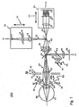
- Fig. 1 is a view roughly showing an optical system 100 of an eye optical characteristic measuring apparatus of the invention.
- the optical system 100 of the eye optical characteristic measuring apparatus is an apparatus for measuring, for example, an optical characteristic of an eye 60 to be measured as an obj ect, and includes a first illuminating optical system 10, a first light receiving optical system 20, a second light receiving optical system 30, a common optical system 40, an adjusting optical system 50, a second illuminating optical system 70, and a second light sending optical system 80.
- a retina 61 and a cornea 62 are shown in the drawing.
- the first illuminating optical system 10 includes, for example, a first light source part 11 for emitting a light flux of a first wavelength, and a condensing lens 12, and is for illuminating a minute region on the retina (eyeground) 61 of the eye 60 to be measured with the light flux from the first light source part 11 so that its illumination condition can be suitably set.
- the first wavelength of the illuminating light flux emitted from the first light source part 11 is a wavelength of an infrared range (for example, 780 nm).It is not limited to the wavelength, a illuminating light flux of a specified wavelength can be used.
- the first light source part 11 has a large spatial coherence and a small temporal coherence.
- the first light source part 11 is, for example, a super luminescence diode (SLD), and a point light source having high luminescence can be obtained.
- SLD super luminescence diode
- the first light source part 11 is not limited to the SLD, and for example, a laser having a large spatial coherence and a large temporal coherence can also be used by combining a rotary prism described later. Further, an LED having a small spatial coherence and a small temporal coherence can also be used, if light quantity is sufficient, by inserting, for example, a pinhole or the like at a position of a light source in an optical path.
- a wedge-shaped rotary prism (D prism) 16 is inserted in the illumination optical system. Since an illuminated portion on the retina is operated by the rotation of the rotary prism, the reflected light from the retina becomes uniform, and it is possible to uniform the received light flux (point image) of the light receiving part.
- the first light receiving optical system 20 includes, for example, a collimator lens 21, a Hartmann plate 22 as a conversion member for converting a part of a light flux (first light flux) reflected and returned from the retina 61 of the eye 60 to be measured into at least 17 beams, and a first light receiving part 23 for receiving the plural beams converted by the Hartmann plate 22, and is for guiding the first light flux to the first light receiving part 23.
- a CCD with little readout noise is adopted for the first light receiving part 23, and as the CCD, a suitable type of CCD, for example, a general low noise type of CCD, a cooling CCD of 1000 * 1000 elements for measurement, or the like can be applied.
- the second illuminating optical system 70 includes a second light source 72 and a Placido's disk 71.
- the second light source 72 can be omitted.
- Fig. 2 shows an example of a structural view of the Placido's disk.
- the Placido's disk 71 is for proj ecting an index of a pattern composed of plural co-axial rings.
- the index of the pattern composed of the plural co-axial rings is an example of an index of a specified pattern, and a different suitable pattern can be used. Then, after an alignment adjustment described later is completed, the index of the pattern composed of the plural co-axial rings can be projected.
- the second light sending optical system 80 is for mainly performing, for example, the alignment adjustment described later, and measurement and adjustment of a coordinate origin and a coordinate axis, and includes a second light source part 31 for emitting a light flux of a second wavelength, a condensing lens 32, and a beam splitter 33.
- the second light receiving optical system 30 includes a condensing lens 34 and a second light receiving part 35.
- the second light receiving optical system 30 guides a light flux (second light flux), which is originated from the pattern of the Placido's disk 71 illuminated from the second illuminating optical system 70 and is reflected and returned from the anterior eye part or the cornea 62 of the eye 60 to be measured, to the second light receiving part 35.
- a light flux which is emitted from the second light source part 31 and is reflected and returned from the cornea 62 of the eye 60 to be measured, to the second light receiving part 35.
- the second wavelength of the light flux emitted from the second light source part 31 for example, a wavelength different from the first wavelength (here, 780 nm) and longer than that (for example, 940 nm) can be selected.
- the common optical system 40 is disposed on an optical axis of the light flux emitted from the first illuminating optical system 10, can be included in the first and the second illuminating optical systems 10 and 70, the first and the second light receiving optical systems 20 and 30, the second light sending optical system 80 and the like in common, and includes, for example, an afocal lens 42, beam splitters 43 and 45, and a condensing lens 44.
- the beam splitter 43 is formed of such a mirror (for example, a polarization beam splitter) that the wavelength of the second light source part 31 is sent (reflected) to the eye 60 to be measured, the second light flux reflected and returned from the retina 61 of the eye 60 to be measured is reflected, and the wavelength of the first light source part 11 is transmitted.
- the beam splitter 45 is formed of such a mirror (for example, a dichroic mirror) that the wavelength of the first light source part 11 is sent (reflected) to the eye 60 to be measured, and the first light flux reflected and returned from the retina 61 of the eye 60 to be measured is transmitted.
- a mirror for example, a dichroic mirror
- the adjusting optical system 50 is for mainly performing, for example, a working distance adjustment described later, includes a third light source part 51, a fourth light source part 55, condensing lenses 52 and 53, and a third light receiving part 54, and is for mainly performing the working distance adjustment.
- the alignment adjustment is mainly carried out by the second light receiving optical system 30 and the second light sending optical system 80.
- the light flux from the second light source part 31 illuminates the eye 60 to be measured as the object with the substantially parallel light flux through the condensing lens 32, the beam splitters 33 and 43, and the afocal lens 42.
- the reflected light flux reflected by the cornea 62 of the eye 60 to be measured is emitted as a divergent light flux such as is emitted from a point at the half of the radius of curvature of the cornea 62.
- the divergence light flux is received as a spot image by the second light receiving part 35 through the afocal lens 42, the beam splitters 43 and 33, and the condensing lens 34.
- the main body of the eye optical characteristic measuring apparatus is moved and adjusted vertically and horizontally, and the spot image is made to coincide with the optical axis.
- the alignment adjustment is completed.
- the cornea 62 of the eye 60 to be measured is illuminated by the third light source 51, and an image of the eye 60 to be measured obtained by this illumination is formed on the second light receiving part 35, and accordingly, this image may be used to make the pupil center coincide with the optical axis.
- the working distance adjustment is mainly carried out by the adjusting optical system 50.
- the working distance adjustment is carried out by, for example, irradiating the eye 60 to be measured with a parallel light flux emitted from the fourth light source part 55 and close to the optical axis, and by receiving the light reflected from the eye 60 to be measured through the condensing lenses 52 and 53 by the third light receiving part 54.
- a spot image from the fourth light source part 55 is formed on the optical axis of the third light receiving part 54.
- the spot image from the fourth light source part 55 is formed above or below the optical axis of the third light receiving part 54.
- the third light receiving part 54 since the third light receiving part 54 has only to be capable of detecting a change of a light flux position on the plane containing the fourth light source part 55, the optical axis and the third light receiving part 54, for example, a one-dimensional CCD arranged on this plane, a position sensing device (PSD) or the like can be applied.
- PSD position sensing device
- the beam splitter 45 is inserted in the first light receiving optical system 20, and by this beam splitter 45, the light from the first illuminating optical system 10 is sent to the eye 60 to be measured, and the reflected light from the eye 60 to be measured is transmitted.
- the first light receiving part 23 included in the first light receiving optical system 20 receives the light transmitted through the Hartmann plate 22 as the conversion member and generates a received light signal.
- the first light source part 11 and the retina 61 of the subject eye 60 form a conjugated relation.
- the retina 61 of the subject eye 60 and the first light receiving part 23 are conjugated.
- the Hartmann plate 22 and the pupil of the subject eye 60 form a conjugated relation.
- the cornea 62 as the anterior eye part of the subject eye 60 and the pupil, and the Hartmann plate 22 form a substantially conjugated relation. That is, the front focal point of the afocal lens 42 is substantially coincident with the cornea 62 as the anterior eye part of the subject eye 60 and the pupil.
- the plane of the rotary prism 16 inclined with respect to the optical axis is disposed at a substantially conjugated position with respect to the pupil.
- the first illuminating optical system 10 and the first light receiving optical system 20 are moved together so that a signal peak by the reflected light at the first light receiving part 23 becomes maximum on the condition that the light flux from the first light source part 11 is reflected at a point on which it is condensed. Specifically, the first illuminating optical system 10 and the first light receiving optical system 20 are moved in a direction in which the signal peak at the first light receiving part 23 becomes large, and are stopped at a position where the signal peak becomes maximum. By this, the light flux from the first light source part 11 is condensed on the eye 60 to be measured.
- the lens 12 converts a diffused light of the light source 11 into a parallel light.
- a diaphragm 14 is positioned at an optically conjugated position with respect to the pupil of the eye or the Hartmann plate 22.
- the diaphragm 14 has a diameter smaller than an effective range of the Hartmann plate 22, and the so-called single path aberrations measurement (method in which the aberrations of the eye has an influence on only the light receiving side) is established.
- the lens 13 is disposed such that the conjugated point of the retina of the real light beam coincides with the front focal position, and further, in order to satisfy the conjugated relation between the lens and the pupil of the eye, it is disposed such that the rear focal position coincides with the diaphragm 14.
- the beam diameter of the light beam 15 is, for example, about 1 mm at the pupil position of the eye, and the beam diameter of the light beam 24 can be about 7 mm (incidentally, in the drawing, the light beam 15 from the beam splitter 45 to the retina 61 is omitted).
- the Hartmann plate 22 included in the first light receiving optical system 20 is a wavefront conversion member for converting a reflected light flux into plural beams.
- plural micro-Fresnel lenses disposed on a plane orthogonal to the optical axis are applied to the Hartmann plate 22.
- the measuring object part the eye 60 to be measured
- a third-order astigmatism, and other higher order aberrations it is necessary to perform the measurement with at least 17 beams through the eye 60 to be measured.
- the micro-Fresnel lens is an optical element, and includes, for example, a ring with a height pitch for each wavelength, and a blade optimized for emission parallel to a condensing point.
- the micro-Fresnel lens here is subjected to, for example, 8-level optical path length variation employing a semiconductor fine working technique, and achieves a high condensing efficiency (for example, 98 %).
- the reflected light from the retina 61 of the eye 60 to be measured passes through the afocal lens 42 and the collimate lens 21, and is condensed on the first light receiving part 23 through the Hartmann plate 22.
- the Hartmann plate 22 includes a wavefront conversion member for converting the reflected light flux into at least 17 beams.
- Fig. 3 is a block diagram roughly showing an electrical system 200 of the eye optical characteristic measuring apparatus of the invention.
- the electrical system 200 of the eye optical characteristic measuring apparatus includes, for example, an arithmetic part 210, a control part 220, a display part 230, a memory, 240, a first driving part 250, and a second driving part 260.
- the arithmetic part 210 receives a received light signal (first signal) (4) obtained from the first light receiving part 23, a received light signal (second signal) (7) obtained from the second light receiving part 35, and a received light signal (10) obtained fromthe third light receiving part 54, andperforms an arithmetical operation on the origin of coordinates, a coordinate axis, movement of coordinates, rotation, ocular aberrations, corneal higher order aberrations, Zernike coefficients, aberration coefficients, a Strehl ratio, a white light MTF, a Landolt's ring pattern and the like.
- signals corresponding to such calculation results are outputted to the control part 220 for performing the whole control of an electric driving system, the display part 230, and the memory 240, respectively.
- the details of the arithmetic part 210 will be described later.
- the control part 220 controls lighting and lights-out of the first light source part 11 on the basis of the control signal from the arithmetic part 210, or controls the first driving part 250 and the second driving part 260.
- the control part outputs a signal (1) to the first light source part 11, outputs a signal (5) to the Placido's disk 71, outputs a signal (6) to the second light source part 31, outputs a signal (8) to the third light source part 51, outputs a signal (9) to the fourth light source part 55, and outputs signals to the first driving part 250 and the second driving part 260.
- the first driving part 250 is for moving the whole first illuminating optical system 10 in the optical axis direction on the basis of, for example, the received light signal (4) inputted to the arithmetic part 210 from the first light receiving part 23, and outputs a signal (2) to a not-shown suitable lens movement means and drives the lens movement means.
- the first driving part 250 can perform the movement and adjustment of the first illuminating optical system 10.
- the second driving part 260 is for moving the whole first light receiving optical system 20 in the optical axis direction on the basis of, for example, the received light signal (4) inputted to the arithmetic part 210 from the first light receiving part 23, and outputs a signal (3) to a not-shown suitable lens movement means, and drives the lens movement means.
- the second driving part 260 can perform the movement and adjustment of the first light receiving optical system 20.
- Fig. 4 is a detailed structural view concerning the arithmetic part of the eye optical characteristic measuring apparatus of the invention.
- the arithmetic part 210 includes a measurement part 111, an analysis part 111', a coordinate setting part 112, an alignment control part 113, a marker setting part 114, an input/output part 115, and a conversion part 116.
- the first light receiving part 23 forms a first received light signal from a received light flux reflected and returned from the retina of the subj ect eye and guides it to the measurement part 111.
- the second light receiving part 35 forms a second received light signal including information of the anterior eye part from the received light flux including information relating to the feature portion of the anterior eye part of the subject eye and/or a marker formed at the anterior eye part of the subject eye, and guides it to the measurement part 111 and the coordinate setting part 112.
- the measurement part 111 obtains the optical characteristics including the refractive power of the subject eye or the corneal formation on the basis of the first received light signal from the first light receiving part. Besides, the measurement part 111 sends the first received light signal to the analysis part 111' for obtaining the spot diameter of the received light flux and the scattering degree of the received light flux.
- the analysis part 111' may be constructed so as to directly receive the first received light signal from the first light receiving part 23. The details of the analysis part 111' will be described later.
- the measurement part 111 performs the eye optical characteristic measurement especially on the basis of the first received light signal from the first light receiving part 23.
- the measurement part 111 performs the cornea topography measurement especially on the basis of the second received light signal from the second light receiving part 35. Besides, the measurement part 111 performs calculation of aberrations results, and calculation of an aberration amount as the need arises, and outputs the calculation results to a surgical apparatus through the output part 115.
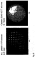
- Fig. 5 is a view in which a part of an image received by the first light receiving part 23 is enlarged.
- the drawing (A) shows a keratoconic eye
- the drawing (B) shows an example of a Hartmann image in the case of a cataractous eye.
- the Hartmann image received by the first light receiving part 23 is, for example, the image on the basis of the reflected light from the subject eye, and includes plural area points (circles, ellipses, etc. in the drawing) in the case where the reflected light is received onto the first light receiving part 23 as light fluxes diffused generally outward through the Hartmann plate 22.
- An optical signal of the Hartmann image in this example is converted into an electrical signal, and is inputted (or captured) as the first signal to the analysis part 111'.
- the information from the Hartmann-Shack wavefront sensor includes the following.
- Wavefront from the barycenter of the point image (classical aberration measurement).
- the scattering amount is estimated by comparing the Hartmann image obtained by the measurement with the Hartmann image restored from the wavefront aberrations.
- the analysis part 111' regards the plural area points as one of the received light fluxes, and obtains the spot diameter of the received light flux and the ratio of the maximum value of the light amount of the received light flux to the minimum value, that is, the scattering degree of the received light flux.
- the analysis part 111' obtains the distribution indicating the relation between the wavefront aberrations of the light flux incident on the light receiving optical system and the scattering degree of the received light flux. Besides, it obtains the distribution indicating the relation between the wavefront aberrations of the light flux incident on the light receiving optical system and the spot diameter of the received light flux.
- the analysis part 111' obtains the distribution concerning the correlation among the wavefront aberrations of the light flux incident on the light receiving optical system, the scattering degree of the received light flux, and the spot diameter of the received light flux, a limitation is not made to the foregoing distribution.
- the analysis part 111' obtains the point spread function (PSF) by wave optical calculation from the wavefront aberrations of the light flux incident on the light receiving system, and has a calculation function to compare this with the diameter of the received light flux, that is, the point spread function (PSF) obtained by actually measuring the intensity from the image.
- PSF point spread function
- the foregoing analysis of the analysis part 111' may correspond to plural specified point images of the Hartmann image, and in this condition, as the result of one measurement, the respective point images may be analyzed in the calculation, or an average value of actually measured values may be used.
- the analysis part 111' judges that as the obtained scattering degree of the received light flux of the light flux incident on the light receiving optical system as the first light receiving part becomes high, the influence of the cataract or the like becomes large, and can output that to the display part 240. Besides, the analysis part 111' judges that as the obtained spot diameter of the received light flux in the light receiving optical system as the first light receiving part becomes large, the influence of the cataract or the like becomes large, and can output that to the display part 240.
- the judgment result, analysis result and the like by the analysis part 111' may be displayed in various forms, such as data, table, graph, three-dimensional display and graphic, on the display part 240, or may be outputted to a recording medium, such as a CD-ROM, a FD or an MO, or another apparatus by the output part.
- a recording medium such as a CD-ROM, a FD or an MO
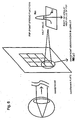
- Fig. 6 is an explanatory view for obtaining the point spread function from the wavefront.
- the wavefront of the light flux reflected from the retina of the subject eye passes through the Hartmann plate, and the wavefront aberrations RMS in a lenslet are obtained from the inclination of the light flux at that time, and a factor such as an area of a half-value portion of the point spread function PSF is obtained.
- the analysis part 111' can obtain a scattering coefficient in a manner as indicated by a following expression.
- Index A -( a ⁇ RMS SL - c )
- Index scattering prediction coefficient (also called scattering prediction index)
- RMS SL wavefront aberrations (average) in the lenslet portion
- c scattering correction constant of measuring apparatus
- a and c are coefficients of a regression line obtained in Fig. 7 by using a keratoconic eye and a normal eye.
- a first-order coefficient of 28.894
- c constant term of 8.6623.
- This scattering coefficient is obtained for the respective lenslets by using various factors of the respective lenslets.
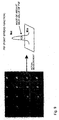
- the relation between the picture of the point image and the point image intensity is as shown in Fig. 9.
- a CCD that a gamma value indicating a relation between a light amount and an output becomes 1
- the intensity distribution of the PSF is proportional to the digital count (computer count) of the CCD
- the minimum intensity and the maximum intensity are obtained in a quadrangle 0. 6 mm square with the point image as the center, and a son contrast ratio can also be obtained from this, and an area at an intermediate point between the minimum intensity and the maximum intensity can also be obtained.
- the point spread function (PSF) of Fig. 6 is obtained from the wavefront aberrations by calculation, and this is compared with the actually measured PSF.
- the coordinate setting part 112 converts signals of a first and a second coordinate systems corresponding to the pupil of the subject eye included in the first and the second received light signals into signals of reference coordinate systems, respectively.
- the coordinate setting part 112 obtains a pupil edge and a pupil center on the basis of the respective signals of the first and the second coordinate systems.
- the coordinate settingpart 112 decides the origin of coordinates and the direction of a coordinate axis on the basis of the second received light signal including feature signals of the anterior eye part of the subject eye. Besides, the coordinate setting part 112 obtains the origin of the coordinates, and the rotation and movement of the coordinate axis on the basis of at least one of the feature signals of the anterior eye part of the subject eye of the second received light signal, and correlates the measurement data with the coordinate axis.
- the feature portion includes at least one of a pupil position, a pupil center, a corneal center, an iris position, an iris pattern, a pupil shape, and a limbus shape.
- the coordinate setting part 112 sets the origin of the coordinates, such as the pupil center or the corneal center.
- the coordinate setting part 112 forms the coordinate system on the basis of the feature signal corresponding to the image of the feature portion of the anterior eye part of the subject eye included in the second received light signal.
- the coordinate setting part 112 forms the coordinate system on the basis of a marker signal included in the second received light signal and concerning a marker provided on the subject eye, and a signal concerning the anterior eye part of the subject eye.
- the coordinate setting part 112 can decide the origin of the coordinates and the direction of the coordinate axis on the basis of the second received light signal including the marker signal.
- the coordinate setting part 112 obtains the origin of the coordinates on the basis of the marker signal in the second received light signal, obtains the rotation and movement of the coordinate axis on the basis of any one of the feature signals of the anterior eye part of the subject eye in the second received light signal, and can correlate the measurement data with the coordinate axis.
- the coordinate setting part 112 obtains the origin of the coordinates on the basis of at least one of the feature signals concerning the anterior eye part in the second received light signal, obtains the rotation and movement of the coordinate axis on the basis of the marker signal in the second received light signal, and may correlate the measurement data with the coordinate axis.
- the coordinate setting part 112 obtains the origin of the coordinates and the rotation and movement of the coordinate axis on the basis of at least one of the feature signals of the anterior eye part of the subject eye in the second received light signal, and may correlate the measurement data with the coordinate axis.
- the conversion part 116 correlates the first and the second optical characteristics of the subject eye obtained by the measurement part 111 through the respective reference coordinate systems formed by the coordinate setting part and combines them. Besides, the conversion part 116 performs conversion to the reference coordinate system by making the pupil center obtained by the coordinate setting part 112 the origin.
- the alignment control part 113 can move this alignment part according to the movement of the subj ect eye and in accordance with the operation result of the coordinate setting part 112 on the basis of the second received light signal obtained by the second light receiving part.
- the marker setting part 114 forms a marker correlated with the coordinate system on the anterior eye part of the subject eye.
- the input/output part 115 is an interface for outputting data and operation results of the aberration amount, the origin of coordinates, the coordinate axis, the rotation and movement of the coordinate axis, and the ablation amount to the surgical apparatus.
- a display part 240 displays the optical characteristic of the subject eye obtained by the measurement part 111 in relation to the coordinate system formed by the coordinate setting part.
- a surgical apparatus 300 includes a surgical control part 121, a working part 122, and a memory part 123.
- the surgical control part 121 controls the working part 122, and controls a surgical operation such as corneal refractive surgery.
- the working part 122 includes a laser for the surgical operation such as corneal refractive surgery.
- the surgical memory part 123 stores data for the surgical operation, such as data concerning cutting, a nomogram, a surgical schedule and the like.
- Fig. 7 shows a view (1) of experimental results by the eye optical characteristic measuring apparatus of this embodiment.
- 9 normal eyes, 24 keratoconic eyes, and 17 cataractous eyes were measured, and the half-value widths were obtained.
- the normal eye (normal) is indicated by rhombus ( ⁇ )
- the keratoconic eye (keratoconus) is indicated by square ( ⁇ )
- the cataractous eye (cataract) is indicated by triangle ( ⁇ ).
- the measurement part 111 or the analysis part 111' analyses the output result from the first received light signal (4) by a specified analytic method. That is, the blur of the received laser light is considered to be the scattered light, and there is obtained the half-value width (square root of area for apots) on the basis of the size of the spot diameter of the received light flux or the ratio of the maximum received light amount of the received light flux to the minimum received light amount, that is, the scatter intensity ratio (minimum intensity/maximum intensity, scattering coefficient) is obtained. Besides, the measurement part 111 or the analysis part 111' prepares the distribution (Fig. 6) of the spot diameter of the received light flux or the distribution of the scatter intensity ratio of the received light flux with respect to the phase (standard deviation) of the wavefront aberrations incident on the first light receiving part 23, which are obtained by the light receiving optical system.
- the cataractous eye since it deviates from the approximated straight line, it can be differentiated from the keratoconic eye. That is, on the basis of the obtained straight line approximation, a test subject who is suspected of having the cataractous eye is discriminated, and this can be used as information for making a decision about the surgery and remedy.
- Fig. 8 shows a view (2) of experimental results by the eye optical characteristic measuring apparatus of this embodiment.
- the correction by eq. (1) is added to the half-value width of Fig. 7.
- the vertical axis indicates an amount obtained by subtracting a value obtained by substituting the wavefront aberrations of the lenslet into eq. (1) from the half-value width.
- obtained values are arranged substantially horizontally.
- this value becomes large.
- a model eye whose scattering can be neglected is measured, and it is also conceivable that a correction is further performed by this measurement value to make the estimate of the scattering amount more accurate.
- the method used here is suitable for the measurement of the crystalline lens scattering, it is also conceivable to apply this to measurement of retina scattering or the like.
- the eye optical characteristic measuring apparatus which enables the scattering measurement by the Hartmann-Shack wavefront sensor whose main object is wavefront aberration measurement, and can accurately estimate the visual functions by performing the scattering measurement.
- the scattering analytic method is developed in which the scattering amount is estimated from the scatter intensity ratio (SIR) of background light of the Hartmann image, and the eye optical characteristic measuring apparatus which can enable simultaneous measurement of scattering by the optical system of the Hartmann-Shack wavefront sensor can be provided.
- SIR scatter intensity ratio
- the eye optical characteristic measuring apparatus can be provided which can make the judgment that from the distribution of relations between the wavefront aberrations of the light flux incident on the light receiving optical system and the scattering degree of the received light flux, as the wavefront aberrations of the light flux incident on the light receiving optical system and the scattering degree of the received light flux become high, the influence of the cataract becomes large.
- the eye optical characteristic measuring apparatus can be provided which can make the judgment that from the distribution of relations among the wavefront aberrations of the light flux incident on the light receiving optical system, the scattering degree of the received light flux, and the spot diameter of the received light flux, as the wavefront aberrations of the light flux incident on the light receiving optical system and the scattering degree of the received light flux become high, or as the spot diameter of the received light flux becomes large, the influence of the cataract becomes large.
Landscapes
- Life Sciences & Earth Sciences (AREA)
- Health & Medical Sciences (AREA)
- Medical Informatics (AREA)
- Biophysics (AREA)
- Ophthalmology & Optometry (AREA)
- Engineering & Computer Science (AREA)
- Biomedical Technology (AREA)
- Heart & Thoracic Surgery (AREA)
- Physics & Mathematics (AREA)
- Molecular Biology (AREA)
- Surgery (AREA)
- Animal Behavior & Ethology (AREA)
- General Health & Medical Sciences (AREA)
- Public Health (AREA)
- Veterinary Medicine (AREA)
- Eye Examination Apparatus (AREA)
Applications Claiming Priority (3)
| Application Number | Priority Date | Filing Date | Title |
|---|---|---|---|
| JP2001271679 | 2001-09-07 | ||
| JP2001271679 | 2001-09-07 | ||
| PCT/JP2002/008197 WO2003022138A1 (fr) | 2001-09-07 | 2002-08-09 | Instrument de mesure de caracteristique optique de l'oeil |
Publications (2)
| Publication Number | Publication Date |
|---|---|
| EP1437084A1 true EP1437084A1 (de) | 2004-07-14 |
| EP1437084B1 EP1437084B1 (de) | 2011-02-23 |
Family
ID=19097158
Family Applications (1)
| Application Number | Title | Priority Date | Filing Date |
|---|---|---|---|
| EP02758825A Expired - Lifetime EP1437084B1 (de) | 2001-09-07 | 2002-08-09 | Instrument zur messung von optischen merkmalen der augen |
Country Status (6)
| Country | Link |
|---|---|
| US (2) | US7311402B2 (de) |
| EP (1) | EP1437084B1 (de) |
| JP (1) | JP4191600B2 (de) |
| AT (1) | ATE499039T1 (de) |
| DE (1) | DE60239278D1 (de) |
| WO (1) | WO2003022138A1 (de) |
Cited By (2)
| Publication number | Priority date | Publication date | Assignee | Title |
|---|---|---|---|---|
| GB2399627A (en) * | 2003-01-21 | 2004-09-22 | Topcon Corp | Ophthalmologic apparatus for dry eye evaluation |
| US7896498B2 (en) | 2009-03-30 | 2011-03-01 | Ottawa Hospital Research Institute | Apparatus and method for optical measurements |
Families Citing this family (23)
| Publication number | Priority date | Publication date | Assignee | Title |
|---|---|---|---|---|
| US7458683B2 (en) * | 2003-06-16 | 2008-12-02 | Amo Manufacturing Usa, Llc | Methods and devices for registering optical measurement datasets of an optical system |
| DE10344781A1 (de) * | 2003-09-23 | 2005-04-14 | Carl Zeiss Meditec Ag | Verfahren zur Bestimmung einer Intraokularlinse |
| JP4528049B2 (ja) * | 2004-07-29 | 2010-08-18 | 株式会社トプコン | 眼科装置 |
| JP4679945B2 (ja) * | 2005-03-30 | 2011-05-11 | 株式会社トプコン | 光学特性測定装置 |
| JP4630107B2 (ja) * | 2005-03-31 | 2011-02-09 | 株式会社トプコン | 眼光学特性測定装置 |
| US20080170205A1 (en) * | 2007-01-11 | 2008-07-17 | Munger Rejean J | Method and apparatus for correlated ophthalmic measurements |
| US8092021B1 (en) * | 2007-01-26 | 2012-01-10 | Aoptix Technologies, Inc. | On-axis illumination for iris imaging |
| WO2008092156A1 (en) * | 2007-01-26 | 2008-07-31 | Aoptix Technologies, Inc. | Combined iris imager and wavefront sensor |
| US7832864B2 (en) * | 2007-06-15 | 2010-11-16 | The Arizona Board Of Regents On Behalf Of The University Of Arizona | Inverse optical design |
| JP5301908B2 (ja) * | 2007-09-03 | 2013-09-25 | 株式会社ニデック | 眼屈折力測定装置 |
| US8331712B2 (en) * | 2008-06-25 | 2012-12-11 | Industrial Technology Research Institute | Method for designing computational optical imaging system |
| JP5539089B2 (ja) | 2010-07-23 | 2014-07-02 | キヤノン株式会社 | 眼科装置、眼科装置の制御方法及びプログラム |
| DE102011102355B4 (de) * | 2011-05-24 | 2025-11-27 | Carl Zeiss Meditec Ag | System zur Bestimmung der Topographie der Kornea eines Auges |
| US9122926B2 (en) | 2012-07-19 | 2015-09-01 | Honeywell International Inc. | Iris recognition using localized Zernike moments |
| CN104905763B (zh) | 2015-06-18 | 2017-12-19 | 苏州四海通仪器有限公司 | 可测量旁中心离焦的验光装置 |
| JP6898712B2 (ja) * | 2016-05-31 | 2021-07-07 | 株式会社トプコン | 眼科装置 |
| JP6736356B2 (ja) * | 2016-05-31 | 2020-08-05 | 株式会社トプコン | 眼科装置 |
| JP6775337B2 (ja) * | 2016-06-28 | 2020-10-28 | 株式会社トプコン | 眼科装置 |
| JP2018117842A (ja) * | 2017-01-25 | 2018-08-02 | 株式会社トプコン | 眼科測定装置 |
| US20230000341A1 (en) * | 2020-01-17 | 2023-01-05 | Haag-Streit Ag | Oct-based, spatially resolved transmission measurement of the eye |
| CN111743510B (zh) * | 2020-06-24 | 2023-09-19 | 中国科学院光电技术研究所 | 一种基于聚类的人眼哈特曼光斑图像去噪方法 |
| CN116507267A (zh) * | 2020-09-22 | 2023-07-28 | 苹果公司 | 用于视网膜眼睛跟踪的多个注视相关照明源 |
| CN116490117A (zh) | 2020-10-27 | 2023-07-25 | 株式会社拓普康 | 眼科观察装置 |
Family Cites Families (8)
| Publication number | Priority date | Publication date | Assignee | Title |
|---|---|---|---|---|
| JP3630753B2 (ja) | 1995-02-02 | 2005-03-23 | 株式会社ニデック | 眼科測定装置 |
| US6234978B1 (en) * | 1997-02-12 | 2001-05-22 | Kabushiki Kaisha Topcon | Optical characteristic measuring apparatus |
| JP3706940B2 (ja) * | 1997-05-09 | 2005-10-19 | 株式会社トプコン | 眼特性測定装置 |
| JP4651253B2 (ja) * | 1999-07-28 | 2011-03-16 | ヴィスクス インコーポレイテッド | レーザー切除のための水和及び地形計測 |
| JP2001095760A (ja) * | 1999-09-28 | 2001-04-10 | Topcon Corp | 眼の光学特性測定装置 |
| JP4692939B2 (ja) * | 1999-11-15 | 2011-06-01 | 株式会社トプコン | 眼特性測定装置 |
| WO2001047407A1 (en) * | 1999-12-27 | 2001-07-05 | Kabushiki Kaisha Topcon | Optical characteristic measuring instrument |
| US6659613B2 (en) * | 2000-03-27 | 2003-12-09 | Board Of Regents, The University Of Texas System | Methods and systems for measuring local scattering and aberration properties of optical media |
-
2002
- 2002-08-09 AT AT02758825T patent/ATE499039T1/de not_active IP Right Cessation
- 2002-08-09 EP EP02758825A patent/EP1437084B1/de not_active Expired - Lifetime
- 2002-08-09 US US10/488,790 patent/US7311402B2/en not_active Expired - Fee Related
- 2002-08-09 JP JP2003526271A patent/JP4191600B2/ja not_active Expired - Fee Related
- 2002-08-09 DE DE60239278T patent/DE60239278D1/de not_active Expired - Lifetime
- 2002-08-09 WO PCT/JP2002/008197 patent/WO2003022138A1/ja not_active Ceased
-
2007
- 2007-11-15 US US11/940,886 patent/US7677731B2/en not_active Expired - Fee Related
Non-Patent Citations (1)
| Title |
|---|
| See references of WO03022138A1 * |
Cited By (4)
| Publication number | Priority date | Publication date | Assignee | Title |
|---|---|---|---|---|
| GB2399627A (en) * | 2003-01-21 | 2004-09-22 | Topcon Corp | Ophthalmologic apparatus for dry eye evaluation |
| GB2399627B (en) * | 2003-01-21 | 2007-02-28 | Topcon Corp | Ophthalmologic apparatus |
| US7241012B2 (en) | 2003-01-21 | 2007-07-10 | Kabushiki Kaisha Topcon | Ophthalmologic apparatus |
| US7896498B2 (en) | 2009-03-30 | 2011-03-01 | Ottawa Hospital Research Institute | Apparatus and method for optical measurements |
Also Published As
| Publication number | Publication date |
|---|---|
| US7311402B2 (en) | 2007-12-25 |
| JPWO2003022138A1 (ja) | 2004-12-24 |
| DE60239278D1 (de) | 2011-04-07 |
| US20050073647A1 (en) | 2005-04-07 |
| US7677731B2 (en) | 2010-03-16 |
| ATE499039T1 (de) | 2011-03-15 |
| US20080123053A1 (en) | 2008-05-29 |
| WO2003022138A1 (fr) | 2003-03-20 |
| EP1437084B1 (de) | 2011-02-23 |
| JP4191600B2 (ja) | 2008-12-03 |
Similar Documents
| Publication | Publication Date | Title |
|---|---|---|
| US7677731B2 (en) | Eye optical characteristic measuring apparatus | |
| US6685320B2 (en) | Opthalmic characteristic measuring apparatus | |
| US7309126B2 (en) | Eye characteristics measuring device | |
| US7216980B2 (en) | Eye characteristic measuring apparatus | |
| US7241012B2 (en) | Ophthalmologic apparatus | |
| US6273566B1 (en) | Ophthalmologic characteristic measuring apparatus | |
| JP4471680B2 (ja) | 眼科装置 | |
| US7249851B2 (en) | Eye characteristic measuring apparatus | |
| JP4663147B2 (ja) | 眼特性測定装置 | |
| JP2019058470A (ja) | 眼屈折特性測定装置及び方法 | |
| US7222962B2 (en) | Opthalmic measuring apparatus | |
| JP4237537B2 (ja) | 眼科装置 | |
| JP4846938B2 (ja) | 眼特性測定装置 | |
| US7249852B2 (en) | Eye characteristic measuring apparatus | |
| JP7608944B2 (ja) | 眼科装置 | |
| US11963722B2 (en) | Methods and systems for determining change in eye position between successive eye measurements | |
| US6676258B2 (en) | Eye characteristic measurement apparatus with speckle noise reduction | |
| US20060082725A1 (en) | Method and apparatus for measurement and correction of refractive power distribution data | |
| JP4237533B2 (ja) | 眼科装置 | |
| US6685650B2 (en) | Fundus blood flowmeter | |
| JP4255587B2 (ja) | 眼科装置 | |
| US7309127B2 (en) | Ophthalmic measuring apparatus |
Legal Events
| Date | Code | Title | Description |
|---|---|---|---|
| PUAI | Public reference made under article 153(3) epc to a published international application that has entered the european phase |
Free format text: ORIGINAL CODE: 0009012 |
|
| 17P | Request for examination filed |
Effective date: 20040326 |
|
| AK | Designated contracting states |
Kind code of ref document: A1 Designated state(s): AT BE BG CH CY CZ DE DK EE ES FI FR GB GR IE IT LI LU MC NL PT SE SK TR |
|
| AX | Request for extension of the european patent |
Extension state: AL LT LV MK RO SI |
|
| 17Q | First examination report despatched |
Effective date: 20091203 |
|
| GRAP | Despatch of communication of intention to grant a patent |
Free format text: ORIGINAL CODE: EPIDOSNIGR1 |
|
| GRAS | Grant fee paid |
Free format text: ORIGINAL CODE: EPIDOSNIGR3 |
|
| GRAA | (expected) grant |
Free format text: ORIGINAL CODE: 0009210 |
|
| AK | Designated contracting states |
Kind code of ref document: B1 Designated state(s): AT BE BG CH CY CZ DE DK EE ES FI FR GB GR IE IT LI LU MC NL PT SE SK TR |
|
| REG | Reference to a national code |
Ref country code: GB Ref legal event code: FG4D |
|
| REG | Reference to a national code |
Ref country code: CH Ref legal event code: EP |
|
| REG | Reference to a national code |
Ref country code: IE Ref legal event code: FG4D |
|
| REF | Corresponds to: |
Ref document number: 60239278 Country of ref document: DE Date of ref document: 20110407 Kind code of ref document: P |
|
| REG | Reference to a national code |
Ref country code: DE Ref legal event code: R096 Ref document number: 60239278 Country of ref document: DE Effective date: 20110407 |
|
| REG | Reference to a national code |
Ref country code: NL Ref legal event code: VDEP Effective date: 20110223 |
|
| PG25 | Lapsed in a contracting state [announced via postgrant information from national office to epo] |
Ref country code: SE Free format text: LAPSE BECAUSE OF FAILURE TO SUBMIT A TRANSLATION OF THE DESCRIPTION OR TO PAY THE FEE WITHIN THE PRESCRIBED TIME-LIMIT Effective date: 20110223 Ref country code: ES Free format text: LAPSE BECAUSE OF FAILURE TO SUBMIT A TRANSLATION OF THE DESCRIPTION OR TO PAY THE FEE WITHIN THE PRESCRIBED TIME-LIMIT Effective date: 20110603 Ref country code: PT Free format text: LAPSE BECAUSE OF FAILURE TO SUBMIT A TRANSLATION OF THE DESCRIPTION OR TO PAY THE FEE WITHIN THE PRESCRIBED TIME-LIMIT Effective date: 20110623 Ref country code: GR Free format text: LAPSE BECAUSE OF FAILURE TO SUBMIT A TRANSLATION OF THE DESCRIPTION OR TO PAY THE FEE WITHIN THE PRESCRIBED TIME-LIMIT Effective date: 20110524 |
|
| PG25 | Lapsed in a contracting state [announced via postgrant information from national office to epo] |
Ref country code: AT Free format text: LAPSE BECAUSE OF FAILURE TO SUBMIT A TRANSLATION OF THE DESCRIPTION OR TO PAY THE FEE WITHIN THE PRESCRIBED TIME-LIMIT Effective date: 20110223 Ref country code: BE Free format text: LAPSE BECAUSE OF FAILURE TO SUBMIT A TRANSLATION OF THE DESCRIPTION OR TO PAY THE FEE WITHIN THE PRESCRIBED TIME-LIMIT Effective date: 20110223 Ref country code: BG Free format text: LAPSE BECAUSE OF FAILURE TO SUBMIT A TRANSLATION OF THE DESCRIPTION OR TO PAY THE FEE WITHIN THE PRESCRIBED TIME-LIMIT Effective date: 20110523 Ref country code: CY Free format text: LAPSE BECAUSE OF FAILURE TO SUBMIT A TRANSLATION OF THE DESCRIPTION OR TO PAY THE FEE WITHIN THE PRESCRIBED TIME-LIMIT Effective date: 20110223 Ref country code: FI Free format text: LAPSE BECAUSE OF FAILURE TO SUBMIT A TRANSLATION OF THE DESCRIPTION OR TO PAY THE FEE WITHIN THE PRESCRIBED TIME-LIMIT Effective date: 20110223 Ref country code: NL Free format text: LAPSE BECAUSE OF FAILURE TO SUBMIT A TRANSLATION OF THE DESCRIPTION OR TO PAY THE FEE WITHIN THE PRESCRIBED TIME-LIMIT Effective date: 20110223 |
|
| PG25 | Lapsed in a contracting state [announced via postgrant information from national office to epo] |
Ref country code: EE Free format text: LAPSE BECAUSE OF FAILURE TO SUBMIT A TRANSLATION OF THE DESCRIPTION OR TO PAY THE FEE WITHIN THE PRESCRIBED TIME-LIMIT Effective date: 20110223 Ref country code: DK Free format text: LAPSE BECAUSE OF FAILURE TO SUBMIT A TRANSLATION OF THE DESCRIPTION OR TO PAY THE FEE WITHIN THE PRESCRIBED TIME-LIMIT Effective date: 20110223 |
|
| PG25 | Lapsed in a contracting state [announced via postgrant information from national office to epo] |
Ref country code: CZ Free format text: LAPSE BECAUSE OF FAILURE TO SUBMIT A TRANSLATION OF THE DESCRIPTION OR TO PAY THE FEE WITHIN THE PRESCRIBED TIME-LIMIT Effective date: 20110223 Ref country code: SK Free format text: LAPSE BECAUSE OF FAILURE TO SUBMIT A TRANSLATION OF THE DESCRIPTION OR TO PAY THE FEE WITHIN THE PRESCRIBED TIME-LIMIT Effective date: 20110223 |
|
| PGFP | Annual fee paid to national office [announced via postgrant information from national office to epo] |
Ref country code: FR Payment date: 20110901 Year of fee payment: 10 Ref country code: DE Payment date: 20110823 Year of fee payment: 10 |
|
| PLBE | No opposition filed within time limit |
Free format text: ORIGINAL CODE: 0009261 |
|
| STAA | Information on the status of an ep patent application or granted ep patent |
Free format text: STATUS: NO OPPOSITION FILED WITHIN TIME LIMIT |
|
| 26N | No opposition filed |
Effective date: 20111124 |
|
| REG | Reference to a national code |
Ref country code: DE Ref legal event code: R097 Ref document number: 60239278 Country of ref document: DE Effective date: 20111124 |
|
| PG25 | Lapsed in a contracting state [announced via postgrant information from national office to epo] |
Ref country code: MC Free format text: LAPSE BECAUSE OF NON-PAYMENT OF DUE FEES Effective date: 20110831 |
|
| REG | Reference to a national code |
Ref country code: CH Ref legal event code: PL |
|
| PG25 | Lapsed in a contracting state [announced via postgrant information from national office to epo] |
Ref country code: CH Free format text: LAPSE BECAUSE OF NON-PAYMENT OF DUE FEES Effective date: 20110831 Ref country code: LI Free format text: LAPSE BECAUSE OF NON-PAYMENT OF DUE FEES Effective date: 20110831 |
|
| REG | Reference to a national code |
Ref country code: IE Ref legal event code: MM4A |
|
| PG25 | Lapsed in a contracting state [announced via postgrant information from national office to epo] |
Ref country code: IT Free format text: LAPSE BECAUSE OF FAILURE TO SUBMIT A TRANSLATION OF THE DESCRIPTION OR TO PAY THE FEE WITHIN THE PRESCRIBED TIME-LIMIT Effective date: 20110223 |
|
| PG25 | Lapsed in a contracting state [announced via postgrant information from national office to epo] |
Ref country code: IE Free format text: LAPSE BECAUSE OF NON-PAYMENT OF DUE FEES Effective date: 20110809 |
|
| REG | Reference to a national code |
Ref country code: FR Ref legal event code: ST Effective date: 20130430 |
|
| PG25 | Lapsed in a contracting state [announced via postgrant information from national office to epo] |
Ref country code: LU Free format text: LAPSE BECAUSE OF NON-PAYMENT OF DUE FEES Effective date: 20110809 |
|
| PG25 | Lapsed in a contracting state [announced via postgrant information from national office to epo] |
Ref country code: DE Free format text: LAPSE BECAUSE OF NON-PAYMENT OF DUE FEES Effective date: 20130301 |
|
| PG25 | Lapsed in a contracting state [announced via postgrant information from national office to epo] |
Ref country code: FR Free format text: LAPSE BECAUSE OF NON-PAYMENT OF DUE FEES Effective date: 20120831 |
|
| REG | Reference to a national code |
Ref country code: DE Ref legal event code: R119 Ref document number: 60239278 Country of ref document: DE Effective date: 20130301 |
|
| PG25 | Lapsed in a contracting state [announced via postgrant information from national office to epo] |
Ref country code: TR Free format text: LAPSE BECAUSE OF FAILURE TO SUBMIT A TRANSLATION OF THE DESCRIPTION OR TO PAY THE FEE WITHIN THE PRESCRIBED TIME-LIMIT Effective date: 20110223 |
|
| PGFP | Annual fee paid to national office [announced via postgrant information from national office to epo] |
Ref country code: GB Payment date: 20140806 Year of fee payment: 13 |
|
| GBPC | Gb: european patent ceased through non-payment of renewal fee |
Effective date: 20150809 |
|
| PG25 | Lapsed in a contracting state [announced via postgrant information from national office to epo] |
Ref country code: GB Free format text: LAPSE BECAUSE OF NON-PAYMENT OF DUE FEES Effective date: 20150809 |