EP1435524B1 - Dispositif capteur pour batterie - Google Patents
Dispositif capteur pour batterie Download PDFInfo
- Publication number
- EP1435524B1 EP1435524B1 EP04005840A EP04005840A EP1435524B1 EP 1435524 B1 EP1435524 B1 EP 1435524B1 EP 04005840 A EP04005840 A EP 04005840A EP 04005840 A EP04005840 A EP 04005840A EP 1435524 B1 EP1435524 B1 EP 1435524B1
- Authority
- EP
- European Patent Office
- Prior art keywords
- battery
- battery sensor
- resistance
- resistance element
- electronic unit
- Prior art date
- Legal status (The legal status is an assumption and is not a legal conclusion. Google has not performed a legal analysis and makes no representation as to the accuracy of the status listed.)
- Expired - Lifetime
Links
Images


Classifications
-
- H—ELECTRICITY
- H01—ELECTRIC ELEMENTS
- H01R—ELECTRICALLY-CONDUCTIVE CONNECTIONS; STRUCTURAL ASSOCIATIONS OF A PLURALITY OF MUTUALLY-INSULATED ELECTRICAL CONNECTING ELEMENTS; COUPLING DEVICES; CURRENT COLLECTORS
- H01R11/00—Individual connecting elements providing two or more spaced connecting locations for conductive members which are, or may be, thereby interconnected, e.g. end pieces for wires or cables supported by the wire or cable and having means for facilitating electrical connection to some other wire, terminal, or conductive member, blocks of binding posts
- H01R11/11—End pieces or tapping pieces for wires, supported by the wire and for facilitating electrical connection to some other wire, terminal or conductive member
- H01R11/28—End pieces consisting of a ferrule or sleeve
- H01R11/281—End pieces consisting of a ferrule or sleeve for connections to batteries
- H01R11/287—Intermediate parts between battery post and cable end piece
-
- G—PHYSICS
- G01—MEASURING; TESTING
- G01R—MEASURING ELECTRIC VARIABLES; MEASURING MAGNETIC VARIABLES
- G01R1/00—Details of instruments or arrangements of the types included in groups G01R5/00 - G01R13/00 and G01R31/00
- G01R1/20—Modifications of basic electric elements for use in electric measuring instruments; Structural combinations of such elements with such instruments
- G01R1/203—Resistors used for electric measuring, e.g. decade resistors standards, resistors for comparators, series resistors, shunts
-
- G—PHYSICS
- G01—MEASURING; TESTING
- G01R—MEASURING ELECTRIC VARIABLES; MEASURING MAGNETIC VARIABLES
- G01R31/00—Arrangements for testing electric properties; Arrangements for locating electric faults; Arrangements for electrical testing characterised by what is being tested not provided for elsewhere
- G01R31/36—Arrangements for testing, measuring or monitoring the electrical condition of accumulators or electric batteries, e.g. capacity or state of charge [SoC]
- G01R31/382—Arrangements for monitoring battery or accumulator variables, e.g. SoC
- G01R31/3842—Arrangements for monitoring battery or accumulator variables, e.g. SoC combining voltage and current measurements
-
- H—ELECTRICITY
- H01—ELECTRIC ELEMENTS
- H01M—PROCESSES OR MEANS, e.g. BATTERIES, FOR THE DIRECT CONVERSION OF CHEMICAL ENERGY INTO ELECTRICAL ENERGY
- H01M10/00—Secondary cells; Manufacture thereof
- H01M10/42—Methods or arrangements for servicing or maintenance of secondary cells or secondary half-cells
- H01M10/48—Accumulators combined with arrangements for measuring, testing or indicating the condition of cells, e.g. the level or density of the electrolyte
-
- H—ELECTRICITY
- H01—ELECTRIC ELEMENTS
- H01M—PROCESSES OR MEANS, e.g. BATTERIES, FOR THE DIRECT CONVERSION OF CHEMICAL ENERGY INTO ELECTRICAL ENERGY
- H01M50/00—Constructional details or processes of manufacture of the non-active parts of electrochemical cells other than fuel cells, e.g. hybrid cells
- H01M50/50—Current conducting connections for cells or batteries
- H01M50/572—Means for preventing undesired use or discharge
- H01M50/574—Devices or arrangements for the interruption of current
- H01M50/581—Devices or arrangements for the interruption of current in response to temperature
-
- G—PHYSICS
- G01—MEASURING; TESTING
- G01R—MEASURING ELECTRIC VARIABLES; MEASURING MAGNETIC VARIABLES
- G01R31/00—Arrangements for testing electric properties; Arrangements for locating electric faults; Arrangements for electrical testing characterised by what is being tested not provided for elsewhere
- G01R31/005—Testing of electric installations on transport means
- G01R31/006—Testing of electric installations on transport means on road vehicles, e.g. automobiles or trucks
-
- G—PHYSICS
- G01—MEASURING; TESTING
- G01R—MEASURING ELECTRIC VARIABLES; MEASURING MAGNETIC VARIABLES
- G01R31/00—Arrangements for testing electric properties; Arrangements for locating electric faults; Arrangements for electrical testing characterised by what is being tested not provided for elsewhere
- G01R31/36—Arrangements for testing, measuring or monitoring the electrical condition of accumulators or electric batteries, e.g. capacity or state of charge [SoC]
- G01R31/364—Battery terminal connectors with integrated measuring arrangements
-
- G—PHYSICS
- G01—MEASURING; TESTING
- G01R—MEASURING ELECTRIC VARIABLES; MEASURING MAGNETIC VARIABLES
- G01R31/00—Arrangements for testing electric properties; Arrangements for locating electric faults; Arrangements for electrical testing characterised by what is being tested not provided for elsewhere
- G01R31/36—Arrangements for testing, measuring or monitoring the electrical condition of accumulators or electric batteries, e.g. capacity or state of charge [SoC]
- G01R31/374—Arrangements for testing, measuring or monitoring the electrical condition of accumulators or electric batteries, e.g. capacity or state of charge [SoC] with means for correcting the measurement for temperature or ageing
-
- H—ELECTRICITY
- H01—ELECTRIC ELEMENTS
- H01M—PROCESSES OR MEANS, e.g. BATTERIES, FOR THE DIRECT CONVERSION OF CHEMICAL ENERGY INTO ELECTRICAL ENERGY
- H01M2200/00—Safety devices for primary or secondary batteries
- H01M2200/10—Temperature sensitive devices
- H01M2200/108—Normal resistors
-
- H—ELECTRICITY
- H01—ELECTRIC ELEMENTS
- H01R—ELECTRICALLY-CONDUCTIVE CONNECTIONS; STRUCTURAL ASSOCIATIONS OF A PLURALITY OF MUTUALLY-INSULATED ELECTRICAL CONNECTING ELEMENTS; COUPLING DEVICES; CURRENT COLLECTORS
- H01R13/00—Details of coupling devices of the kinds covered by groups H01R12/70 or H01R24/00 - H01R33/00
- H01R13/66—Structural association with built-in electrical component
- H01R13/665—Structural association with built-in electrical component with built-in electronic circuit
- H01R13/6683—Structural association with built-in electrical component with built-in electronic circuit with built-in sensor
-
- Y—GENERAL TAGGING OF NEW TECHNOLOGICAL DEVELOPMENTS; GENERAL TAGGING OF CROSS-SECTIONAL TECHNOLOGIES SPANNING OVER SEVERAL SECTIONS OF THE IPC; TECHNICAL SUBJECTS COVERED BY FORMER USPC CROSS-REFERENCE ART COLLECTIONS [XRACs] AND DIGESTS
- Y02—TECHNOLOGIES OR APPLICATIONS FOR MITIGATION OR ADAPTATION AGAINST CLIMATE CHANGE
- Y02E—REDUCTION OF GREENHOUSE GAS [GHG] EMISSIONS, RELATED TO ENERGY GENERATION, TRANSMISSION OR DISTRIBUTION
- Y02E60/00—Enabling technologies; Technologies with a potential or indirect contribution to GHG emissions mitigation
- Y02E60/10—Energy storage using batteries
Definitions
- the invention relates to a battery sensor.
- a battery sensor device is known, for example, from US 5,939,861.
- the battery sensor is arranged in a specially provided for this recess in the battery cover and must be attached to both poles of the battery.
- Various devices and methods are known for monitoring, controlling and regulating a motor vehicle electrical system, such as energy distribution, energy control and, in particular, charging balance of the batteries.
- a motor vehicle electrical system such as energy distribution, energy control and, in particular, charging balance of the batteries.
- at least the measured quantities battery current, battery voltage and battery temperature are usually necessary.
- To detect the battery current sensors are usually used in the connection cable to the battery.
- the battery voltage and the battery temperature are usually measured by separate sensors directly to the battery terminals or away from it.
- three completely independent devices are usually used, for which space must be created separately in each vehicle and their information usually have to be forwarded to higher-level control devices for further processing.
- shunts are used for example.
- the invention provides an integrated battery sensor is provided which can be installed in each vehicle with little additional effort with only little space required. In addition, the probability of failure is reduced by the compact design and the integration of several necessary components.
- the fastening device of the battery sensor is shown as a preferably conventional battery brass terminal consisting of a clamp body 1 and a clamping screw 2.
- the battery sensor 3, 4 according to the invention is essentially composed of a measuring shunt 3 and an electronic unit 4. 1 a, only the two resistance connections (10 a, 10 b, see also FIG. 2) of the measuring shunt 3 and a plastic encapsulation of the electronic unit 4, which are formed as mechanical supports, are shown.
- the battery sensor 3,4 and the fastening device 1, 2 are preferably combined to form an integrated unit.
- the fastening device 1,2 must only at a single pole of a battery, for. B. at the negative terminal connected become.
- the assembly, consisting of the fastening device 1, 2 and the battery sensor 3,4, is adapted in shape and size to the (not shown here) known, according to the Polish DIN 72311 (Teil15) specified battery pole.
- the first, shown in Fig. 1a above resistor terminal 10a is conductive
- the second, shown in Fig. 1a below resistance terminal 10b is secured in isolation over an insulating part 6 on the clamp body 1.
- the cable lug of a common connection cable can be connected.
- the (not shown here) connecting cable connects the output-side resistor terminal 10b of the Meßshunts 3 with the vehicle mass.
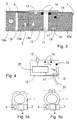
- Fig. 2 the assembly shown in Fig. 1a and 1b is shown in three dimensions to illustrate the construction. The same components are provided with the same reference numerals.
- the Meßshunt 3 consists of a resistive element 11 and two planar resistor terminals 10 a and 10 b.
- the resistor terminals 10a and 10b are preferably stably formed copper surfaces.
- Resistance element 11 is preferably manganin, zeranine or isohm. Copper and manganin / zeranin / lsaohm have about the same coefficient of thermal expansion as the usual board material FR4 (mixed material with epoxy resin as main component).
- This board material is preferably also for the carrier board 12 of the electronics unit 4th used, which is shown in Fig. 3 without plastic extrusion. Therefore, the carrier board 12 of the electronics unit 4 shown in FIG. 3 similar to the SMD technique via bare solder joints 14 can be attached to the resistor terminals 10a and 10b.
- the support plate 12 can also be conductively fixed by 90 ° upwardly bent short sense lines of the resistor terminals 10a and 10b on Meßshunt 3. The solder joints 14 or the terminals of the sense lines are arranged as close as possible to the resistance element 11. About the solder joints 14, the resistance element 11 is integrated circuitry in the electronics unit 4.
- the electronic unit 4 or the carrier board 12 is connected in Fig. 3 with a temperature sensor 13 for measuring the battery temperature.
- Alternative arrangements of the temperature sensor are shown in dashed lines with the reference numerals 13a and 13b.
- the temperature sensor 13 is thermally conductive, for example by means of thermal adhesive directly on the clamp body 1 is arranged. This arrangement allows a very accurate temperature measurement, but is somewhat more expensive than the arrangement of the temperature sensors 13a and 13b, which are attached to the heat-conducting resistor terminal 10b.
- the temperature sensor 13 a is simplified via connecting wires to the carrier board 12 attached.
- the temperature sensor 13b is connected, for example via solder joints with the carrier board 12 to prevent the connecting wires. For the temperature sensor 13b, however, a recess in the carrier board 12 may be necessary.
- the electronic unit 4 or the carrier board 12 has an example two-pin plug 16.
- a supply cable to the other pole of the battery, here to the positive terminal can be connected.
- a bidirectional communication line to other electronic devices in the motor vehicle can be connected.
- the communication line may also require two pins (eg when using a CAN bus).
- the communication can also be carried out by radio transmission.
- a connection via a plug 16 can also be provided with a direct connection of the connection lines to the board (for example by soldering, bonding or welding). (The alternatives are not shown here.)
- a first voltage tap 15 for measuring the battery voltage U Batt is shown, which is conductively connected to the battery terminal (eg to the negative terminal) resistance terminal 10a.
- the second voltage tap for measuring the battery voltage U Batt is formed by the pin 18 (eg to the positive pole of the battery).
- the carrier board 12 or the electronics unit 4 has a measuring, evaluation and control unit 20.
- the unit 20 detects the battery voltage U Batt , the voltage U between the two solder joints 14 and the battery temperature. From the voltage U, the battery current (I) can be calculated. For this purpose, for example, the resistance value (R) of the resistive element 11 is stored in the unit 20.
- the unit 20 preferably comprises a microprocessor and a memory. Also, the unit 20 may include conventional amplifiers and A / D converters for metering.
- the unit 20 may be any other battery indicator sizes, such as. As the state of charge or the state of aging determined. Furthermore, the unit 20 in turn can not only transmit information via the communication line, but also receive further information from other control devices and further process them with the battery sizes.
- the communication line and the supply line to the plug 16 are shown as a harness 21 combined.
- the unit 20 may drive a power switch 19 which can close or open a break present in the resistor terminal 10b.
- the battery supply of the motor vehicle can be switched off in emergencies become.
- the power switch 19 can also be integrated in one of the two connection cables to the positive pole or to the negative pole of the battery and controlled by the unit 20.
- Fig. 5a is complementarily only a second possible construction of the integrated assembly consisting of battery sensor and fastening device shown.
- the hole for the clamping screw 2 is indicated by the dotted line.
- This construction differs only in the first construction, that the battery sensor 3, 4 locally more strongly offset from the clamping screw 2 and thus is decoupled from possible tension in an attachment of the clamp body 1.
- Fig. 5b shows a Fig. 5a very similar construction in which, however, a taper is provided between the clamping body 1 and the Meßshunt 3, to avoid material stresses in the clamping body 1.
- FIGS. 6a to 7a show further design possibilities of the measuring shunt 3 according to the invention consisting of the resistance element 11 and the two resistance terminals 10a and 10b as well as the attachment of the electronics unit 4 or its carrier board 12.
- the resistor terminals 10a and 10b are preferably (as in FIG. 3) planar copper surfaces.
- the material of the resistive element 1, preferably manganin or zeranin, is arranged between the resistor terminals 10a and 10b as in FIG.
- the carrier board 12 of the electronics unit 4 (also similar to the SMD technique) is fastened via solder joints 14 to the resistor terminals 10a and 10b.
- the solder joints 14 an elongated line along the edge of the carrier board 12.
- the solder lines 14 can also be interrupted or also composed of spaced points.
- the width of the carrier board 12 is not much larger than the width of the resistance element 11; because the soldering must be provided as close to the resistance element 11.
- the construction of the Meßshunts is shown in FIG. 7a such that there is a cavity between the resistor element 11 and the carrier board 12.
- the thickness of the resistance element 11 is thus smaller than that of the resistance terminals 10a and 10b. Through this cavity, it is possible to equip the carrier board 12, if necessary, on both sides.
- the carrier board 12 may also be connected as closely as possible to the resistance element 11 by soldering points 14 on the underside of the board 12 with the resistance terminals 10a and 10b (similar to FIG. 3).
- a solid line (FIG. 6b, left) or an interrupted (FIG. 6b, right) solder line are provided for mechanical stabilization (as in FIG. 6a).
- the resistance element 11 is always integrated circuit technology in the electronics unit 4.
- the embodiment according to FIG. 6b can be combined with the construction of the measuring shunt according to FIG. 7a.
- the width of the carrier board 12 can also be greater than the width of the resistance element 11.
- solder joints (14) instead of solder joints (14) also splices (14), e.g. be provided by means of an electrically conductive and thermally conductive adhesive.
- the electronics unit 4 or the carrier board 12 of the electronics unit 4 at the planar resistor terminals 10a and 10b are secured by means of an electrically conductive material 14 (eg solder or glue).
- the soldering or splicing 14 thus serve both for electrical or circuit integration of the Meßshunts or the resistive element 11 in the electronics unit 4 and for mechanical attachment of the electronics unit 4 and the carrier board 12 on Meßshunt or at its resistor terminals 10a and 10b.
Landscapes
- Chemical & Material Sciences (AREA)
- Chemical Kinetics & Catalysis (AREA)
- Electrochemistry (AREA)
- General Chemical & Material Sciences (AREA)
- Physics & Mathematics (AREA)
- General Physics & Mathematics (AREA)
- Engineering & Computer Science (AREA)
- Manufacturing & Machinery (AREA)
- Secondary Cells (AREA)
- Measuring Instrument Details And Bridges, And Automatic Balancing Devices (AREA)
- Measuring Fluid Pressure (AREA)
- Connection Of Batteries Or Terminals (AREA)
- Measuring Pulse, Heart Rate, Blood Pressure Or Blood Flow (AREA)
- Primary Cells (AREA)
- Electrical Discharge Machining, Electrochemical Machining, And Combined Machining (AREA)
- Electric Propulsion And Braking For Vehicles (AREA)
Claims (4)
- Capteur de batterie (3, 4) comprenant un shunt de mesure (3) et une unité électronique (4), dans lequel- le shunt de mesure (3) est constitué de deux branchements de résistance (10a, 10b) planaires et d'une grille de résistance (11) planaire disposé entre les branchements de résistance (10a, 10b) et l'épaisseur de la grille de résistance (11) est inférieure à l'épaisseur des branchements de résistance (10a, 10b), et- l'unité électronique (4), ou sa platine porteuse (12) est fixée sur les branchements de résistance (10a, 10b) au moyen d'un matériau (14) conducteur d'électricité de façon qu'il se forme un espace creux entre la grille de résistance (11) et la platine porteuse (12).
- Capteur de batterie selon la revendication 1,
caractérisé en ce que
l'espace creux est réalisé de façon que la platine porteuse peut être équipée des deux côtés. - Capteur de batterie selon l'une des revendications précédentes,
caractérisé en ce que
la fixation de l'unité électronique (4) et de la platine porteuse (12) est réalisée le plus près possible de la grille de résistance (11). - Capteur de batterie selon l'une des revendications précédentes,
caractérisé en ce que
la fixation de l'unité électronique (4) et de la platine porteuse (12) est réalisée sur les branchements de résistance (10a, 10b) - et en particulier également la liaison technique du circuit entre la grille de résistance (11) et l'unité électronique (4)- au moyen d'une ligne de brasage continue ou discontinue.
Applications Claiming Priority (3)
| Application Number | Priority Date | Filing Date | Title |
|---|---|---|---|
| DE19961311 | 1999-12-18 | ||
| DE19961311A DE19961311A1 (de) | 1999-12-18 | 1999-12-18 | Batteriesensorvorrichtung |
| EP00987376A EP1238288B1 (fr) | 1999-12-18 | 2000-12-09 | Dispositif de capteur pour batterie |
Related Parent Applications (1)
| Application Number | Title | Priority Date | Filing Date |
|---|---|---|---|
| EP00987376A Division EP1238288B1 (fr) | 1999-12-18 | 2000-12-09 | Dispositif de capteur pour batterie |
Publications (2)
| Publication Number | Publication Date |
|---|---|
| EP1435524A1 EP1435524A1 (fr) | 2004-07-07 |
| EP1435524B1 true EP1435524B1 (fr) | 2006-06-21 |
Family
ID=7933323
Family Applications (2)
| Application Number | Title | Priority Date | Filing Date |
|---|---|---|---|
| EP00987376A Expired - Lifetime EP1238288B1 (fr) | 1999-12-18 | 2000-12-09 | Dispositif de capteur pour batterie |
| EP04005840A Expired - Lifetime EP1435524B1 (fr) | 1999-12-18 | 2000-12-09 | Dispositif capteur pour batterie |
Family Applications Before (1)
| Application Number | Title | Priority Date | Filing Date |
|---|---|---|---|
| EP00987376A Expired - Lifetime EP1238288B1 (fr) | 1999-12-18 | 2000-12-09 | Dispositif de capteur pour batterie |
Country Status (8)
| Country | Link |
|---|---|
| US (1) | US6787935B2 (fr) |
| EP (2) | EP1238288B1 (fr) |
| JP (1) | JP4996802B2 (fr) |
| AT (2) | ATE331224T1 (fr) |
| DE (3) | DE19961311A1 (fr) |
| ES (2) | ES2265124T3 (fr) |
| HK (1) | HK1052554B (fr) |
| WO (1) | WO2001044825A1 (fr) |
Cited By (7)
| Publication number | Priority date | Publication date | Assignee | Title |
|---|---|---|---|---|
| DE102008003458A1 (de) * | 2008-01-08 | 2009-07-09 | Robert Bosch Gmbh | Vorrichtung zur Ermittlung eines elektrischen Stroms |
| DE102008003338A1 (de) * | 2008-01-07 | 2009-07-09 | Robert Bosch Gmbh | Vorrichtung zum Ermitteln eines elektrischen Stroms |
| DE102008013407A1 (de) * | 2008-03-10 | 2009-09-17 | Robert Bosch Gmbh | Sensoranordnung für die Zustandserkennung einer Batterie |
| DE102008040243A1 (de) | 2008-07-08 | 2010-01-14 | Robert Bosch Gmbh | Polklemmenanordnung mit integriertem Shuntwiderstand |
| DE102008029476A1 (de) * | 2008-06-20 | 2010-02-18 | Robert Bosch Gmbh | Berührungslos arbeitende Strommessanordnung zur Messung eines Batteriestromes |
| DE102009001374A1 (de) | 2009-03-06 | 2010-09-09 | Robert Bosch Gmbh | Sicherheitssystem für elektronische Baugruppen, insbesondere in einem Fahrzeug |
| DE102009044992A1 (de) | 2009-09-24 | 2011-04-14 | Robert Bosch Gmbh | Verfahren zur Verbesserung der Messung mit einem Batteriesensor |
Families Citing this family (85)
| Publication number | Priority date | Publication date | Assignee | Title |
|---|---|---|---|---|
| DE19835346A1 (de) * | 1998-08-05 | 2000-02-10 | Boehringer Ingelheim Pharma | Zweiteilige Kapsel zur Aufnahme von pharmazeutischen Zubereitungen für Pulverinhalatoren |
| US6628102B2 (en) * | 2001-04-06 | 2003-09-30 | Microchip Technology Inc. | Current measuring terminal assembly for a battery |
| DE10118051B4 (de) * | 2001-04-11 | 2005-09-29 | Daimlerchrysler Ag | Batterienmessklemme mit Fremdstartstützpunkt |
| DE10118027B4 (de) * | 2001-04-11 | 2005-11-10 | Daimlerchrysler Ag | Batteriemessklemme mit Fremdstartstützpunkt und integrierter Meßsensorik |
| DE10332410B3 (de) * | 2003-07-16 | 2004-05-27 | Auto Kabel Managementgesellschaft Mbh | Kraftfahrzeugbordnetzsensorvorrichtung und Verfahren zur Herstellung einer Sensorvorrichtung |
| DE10336107B3 (de) * | 2003-08-06 | 2005-04-28 | Siemens Ag | Messwiderstand für eine Batteriesensorikeinheit und Batteriesensorikeinheit |
| DE10347111B4 (de) * | 2003-10-10 | 2013-02-21 | Continental Automotive Gmbh | Integrierte Batteriemessklemme |
| DE102004006298B4 (de) | 2004-02-09 | 2006-08-17 | Siemens Ag | Verbindungsanordnung für ein Messelement eines Batteriesensors |
| DE102004007851B4 (de) * | 2004-02-17 | 2006-03-16 | Kromberg & Schubert Gmbh & Co. Kg | Anschlussvorrichtung für eine Batterie |
| DE102004013659A1 (de) * | 2004-03-19 | 2005-10-13 | Siemens Ag | Vorrichtung zum Erfassen einer elektrischen Größe eines Akkumulators |
| DE102004033127B3 (de) * | 2004-07-08 | 2006-04-20 | Siemens Ag | Vorrichtung zum Erfassen einer elektrischen Größe eines Akkumulators und Verfahren zum Herstellen einer solchen Vorrichtung |
| JP4494895B2 (ja) * | 2004-07-20 | 2010-06-30 | 古河電気工業株式会社 | バッテリ状態検知ユニット |
| DE102004037194A1 (de) * | 2004-07-30 | 2006-03-23 | Hella Kgaa Hueck & Co. | Vorrichtung zum Messen eines elektrischen Stroms |
| DE102004037874B4 (de) * | 2004-08-04 | 2008-09-04 | Continental Automotive Gmbh | Batteriesensoranordnung |
| DE102004040575A1 (de) * | 2004-08-21 | 2006-02-23 | Abb Patent Gmbh | Einrichtung zum Messen von elektrischem Strom, Spannung und Temperatur an einem aus starrem Material bestehenden elektrischen Leiter |
| DE102004046855B3 (de) * | 2004-09-27 | 2006-04-13 | Siemens Ag | Batteriepolklemmenanordnung |
| DE102004049251A1 (de) | 2004-09-30 | 2006-04-06 | Robert Bosch Gmbh | Gerät zum Ermitteln von elektrischen Größen |
| DE102004049153A1 (de) * | 2004-09-30 | 2006-04-06 | Robert Bosch Gmbh | Leiterabschnitt für ein Gerät zum Ermitteln von elektrischen Größen |
| DE102004053648A1 (de) * | 2004-11-03 | 2006-05-04 | Leopold Kostal Gmbh & Co. Kg | Batteriestromsensor für ein Kraftfahrzeug |
| DE102004055849A1 (de) * | 2004-11-19 | 2006-06-01 | Bayerische Motoren Werke Ag | Batteriesensorvorrichtung |
| DE102004055847B4 (de) * | 2004-11-19 | 2007-01-11 | Bayerische Motoren Werke Ag | Verfahren zur Fertigung einer Batteriesensorvorrichtung |
| DE102004055848B4 (de) * | 2004-11-19 | 2008-02-21 | Bayerische Motoren Werke Ag | Batteriesensorvorrichtung |
| FR2879751B1 (fr) * | 2004-12-20 | 2007-02-23 | Johnson Controls Tech Co | Dispositif de mesure d'un courant circulant dans un cable |
| DE102004063849A1 (de) * | 2004-12-30 | 2006-07-13 | Robert Bosch Gmbh | Energieversorgungssystem für Startvorrichtung |
| DE102005041392B4 (de) * | 2005-04-07 | 2016-02-18 | Kromberg & Schubert Kg | Anschlusseinrichtung |
| DE102005019569A1 (de) * | 2005-04-27 | 2006-11-09 | Siemens Ag | Shunt, Batteriesensor und Verfahren zur Herstellung eines Shunts |
| DE102005021959A1 (de) * | 2005-05-12 | 2006-11-23 | Leopold Kostal Gmbh & Co. Kg | Batteriestromsensor für ein Kraftfahrzeug |
| DE102005034427A1 (de) * | 2005-07-13 | 2007-01-18 | Robert Bosch Gmbh | Polgegenkontakt, insbesondere für Starterakkumulatoren von Kraftfahrzeugen |
| DE102005039587A1 (de) * | 2005-08-19 | 2007-02-22 | Robert Bosch Gmbh | Batteriesensoreinheit |
| US7385828B2 (en) * | 2006-01-27 | 2008-06-10 | Delphi Technologies, Inc. | Electronic shunt resistor assembly |
| DE102007006050B8 (de) * | 2006-02-04 | 2013-04-04 | Kromberg & Schubert Kg | Anschlusseinrichtung |
| DE102006036247A1 (de) * | 2006-02-16 | 2007-08-23 | Kromberg & Schubert Gmbh & Co. Kg | Anschlusseinrichtung |
| US7688022B2 (en) | 2006-02-17 | 2010-03-30 | Lear Corporation | Energy management system for a vehicle |
| DE102006019497B4 (de) * | 2006-04-26 | 2009-04-23 | Continental Automotive Gmbh | Sensorvorrichtung für eine Starterbatterie in einem Kraftfahrzeug |
| DE112006003786A5 (de) * | 2006-04-28 | 2009-03-05 | Daimler Ag | Brennstoffzellenvorrichtung mit einem Stromsensor und Stromsensor für eine Brennstoffzellenvorrichtung |
| DE102006029547A1 (de) * | 2006-06-26 | 2007-12-27 | Robert Bosch Gmbh | Batteriesensoreinheit und Verfahren zur Herstellung der Batteriesensoreinheit |
| DE102006038373A1 (de) * | 2006-08-12 | 2008-02-14 | Robert Bosch Gmbh | Elektrische Vorrichtung |
| US7381101B2 (en) * | 2006-08-25 | 2008-06-03 | Lear Corporation | Battery post connector |
| DE102006046137B4 (de) * | 2006-09-28 | 2019-02-14 | Continental Automotive Gmbh | Batteriesensoreinheit |
| DE102006050573B4 (de) * | 2006-10-26 | 2017-03-09 | Audi Ag | Elektrische Sicherungsvorrichtung für mit einer Batterie verbundene elektrische Verbraucher eines Fahrzeugs |
| DE102006058135A1 (de) * | 2006-12-09 | 2008-06-26 | Kromberg & Schubert Gmbh & Co. Kg | Batterieklemme |
| US7500888B2 (en) * | 2007-02-08 | 2009-03-10 | Lear Corporation | Battery post connector |
| DE102007009569B4 (de) | 2007-02-27 | 2011-06-16 | Kromberg & Schubert Gmbh & Co. Kg | Anschlusseinrichtung und Verfahren zu deren Herstellung |
| DE102007021921B4 (de) * | 2007-05-10 | 2009-03-19 | Siemens Ag | Vorrichtung zum Überwachen eines Energiespeichers |
| US8476864B2 (en) | 2007-06-13 | 2013-07-02 | Lear Corporation | Battery monitoring system |
| DE102007033182B4 (de) * | 2007-07-13 | 2012-11-29 | Auto-Kabel Management Gmbh | Kraftfahrzeugbatteriesensorelement sowie Verfahren zur Herstellung eines Kraftfahrzeugbatteriesensorelements |
| JP4442660B2 (ja) | 2007-08-10 | 2010-03-31 | 株式会社デンソー | 車両システム |
| US8174275B2 (en) * | 2007-12-19 | 2012-05-08 | Kuen-Cheng Wang | Storage battery inspecting system |
| DE102007061111A1 (de) * | 2007-12-19 | 2009-06-25 | Robert Bosch Gmbh | Sensoranordnung und Diagnoseverfahren für die Zustandserkennung einer Batterie in einem Kraftfahrzeug |
| DE102007061113A1 (de) * | 2007-12-19 | 2009-06-25 | Robert Bosch Gmbh | Sensoranordnung für die Zustandserkennung einer Batterie |
| US20090160456A1 (en) * | 2007-12-19 | 2009-06-25 | Kuen-Cheng Wang | Device for inspecting soldering spots in a storage battery |
| JP2009177903A (ja) | 2008-01-23 | 2009-08-06 | Denso Corp | 車両システム |
| DE102008006183A1 (de) * | 2008-01-26 | 2009-07-30 | Hella Kgaa Hueck & Co. | Vorrichtung zur Strommessung |
| KR100910883B1 (ko) | 2008-01-30 | 2009-08-06 | 동아전장주식회사 | 차량용 배터리 센서의 제조 방법 |
| DE102008006866A1 (de) * | 2008-01-31 | 2009-08-06 | Hella Kgaa Hueck & Co. | Vorrichtung zur Strommessung |
| GB0805585D0 (en) | 2008-03-27 | 2008-04-30 | Ultra Electronics Ltd | Current measurement apparatus |
| DE202008017964U1 (de) | 2008-06-23 | 2011-01-05 | Iq Power Licensing Ag | Batteriedeckelkonstruktion mit Batteriepol |
| US8305034B2 (en) * | 2008-07-23 | 2012-11-06 | Lear Corporation | Battery monitoring system |
| DE102009000827A1 (de) * | 2009-02-13 | 2010-08-19 | Robert Bosch Gmbh | Vorrichtung und Verfahren zum Verbinden zumindest zwei elektrischer Anschlüsse |
| ES2381704B1 (es) | 2009-09-23 | 2013-05-08 | Cablerias Auto, S.L | Cable de bateria inteligente |
| DE102009045310A1 (de) * | 2009-10-02 | 2011-04-07 | Robert Bosch Gmbh | Anordnung mit Widerstandselementen zur Strommessung |
| JP5723139B2 (ja) * | 2010-04-30 | 2015-05-27 | 矢崎総業株式会社 | 電流センサ付きバッテリターミナルユニット |
| DE102010036397A1 (de) | 2010-07-14 | 2012-01-19 | Dr. Ing. H.C. F. Porsche Aktiengesellschaft | Automatische Erkennung einer Zellchemie bzw. eines Batterietyps einer Batterie |
| EP2434583A1 (fr) * | 2010-09-28 | 2012-03-28 | Liaisons Electroniques-Mecaniques Lem S.A. | Capteur de courant de batterie |
| JP5873626B2 (ja) * | 2010-10-06 | 2016-03-01 | 矢崎総業株式会社 | バスバー温度を正確に測定できる電流検出装置 |
| US20130073235A1 (en) * | 2011-03-17 | 2013-03-21 | Isophi Bvba | Battery monitoring devices |
| DE102011111081B4 (de) * | 2011-08-18 | 2021-08-05 | Isabellenhütte Heusler Gmbh & Co. Kg | Batteriesensor |
| DE102012210258A1 (de) | 2011-11-18 | 2013-05-23 | Robert Bosch Gmbh | Batterie mit einem Batteriesteuergerät und integriertem Temperatursensor |
| JP6094856B2 (ja) * | 2012-09-28 | 2017-03-15 | 株式会社Gsユアサ | 蓄電装置及び車両並びに接続端子 |
| EP2738562B1 (fr) * | 2012-11-30 | 2015-01-07 | Isabellenhütte Heusler GmbH & Co.KG | Capteur de batterie |
| US20140152313A1 (en) * | 2012-12-03 | 2014-06-05 | Isabellenhuette Heusler Gmbh & Co. Kg | Battery sensor |
| DE102013010166A1 (de) * | 2013-06-19 | 2015-01-08 | Auto-Kabel Management Gmbh | Polnischenintegrierter Startstrombegrenzer |
| US9226412B2 (en) * | 2013-08-02 | 2015-12-29 | Lear Corporation | Housing with air chamber for battery monitor system and method for manufacturing same |
| USD777055S1 (en) | 2014-04-19 | 2017-01-24 | Mark Taylor | Battery monitoring clamp |
| USD777669S1 (en) | 2014-04-19 | 2017-01-31 | Mark Taylor | Battery monitoring clip |
| WO2016042732A1 (fr) * | 2014-09-16 | 2016-03-24 | パナソニックIpマネジメント株式会社 | Dispositif capteur de batterie |
| US20160146900A1 (en) * | 2014-11-24 | 2016-05-26 | Hyundai Mobis Co., Ltd. | Battery sensor assembly for vehicle |
| DE102016210661A1 (de) * | 2016-06-15 | 2017-12-21 | Continental Automotive Gmbh | Stromsparendes Speicherkonzept für Elektronikmodule in einem Kraftfahrzeug |
| DE102017207713A1 (de) * | 2017-05-08 | 2018-11-08 | Robert Bosch Gmbh | Shunt-Widerstand zur Zustandserkennung einer elektrischen Energiespeichereinheit |
| JP2019169396A (ja) * | 2018-03-23 | 2019-10-03 | ダイハツ工業株式会社 | バッテリの温度推定装置 |
| USD853309S1 (en) * | 2018-03-27 | 2019-07-09 | Mt. Ida Machining, Inc. | Automobile battery pole connector set |
| DE102018209325A1 (de) | 2018-06-12 | 2019-12-12 | Bayerische Motoren Werke Aktiengesellschaft | Messungen an Batterien |
| DE102019121980A1 (de) * | 2019-01-22 | 2020-07-23 | Roman Nachsel | Hochstrom-Bauelement |
| DE102021107218A1 (de) * | 2020-03-30 | 2021-09-30 | Sma Solar Technology Ag | Vorrichtung zur Temperaturmessung und Vorrichtung zur Stromermittlung |
| WO2023112985A1 (fr) * | 2021-12-16 | 2023-06-22 | 古河電気工業株式会社 | Dispositif de détection d'état de batterie, système de traitement d'informations et procédé de collecte de données |
Family Cites Families (5)
| Publication number | Priority date | Publication date | Assignee | Title |
|---|---|---|---|---|
| DE2535245A1 (de) * | 1975-08-07 | 1977-02-24 | Bosch Gmbh Robert | Batterieladeeinrichtung |
| US4572878A (en) * | 1984-12-19 | 1986-02-25 | General Motors Corporation | Battery temperature sensor and housing therefor |
| DE3532044A1 (de) * | 1985-09-09 | 1987-03-19 | Vdo Schindling | Polklemme |
| DE19503809B4 (de) * | 1995-02-06 | 2005-01-20 | Bayerische Motoren Werke Ag | Sicherungsvorrichtung für eine Stromleitung in Fahrzeugen |
| US6218805B1 (en) * | 1998-04-17 | 2001-04-17 | Menico Ag | Measuring battery clamps |
-
1999
- 1999-12-18 DE DE19961311A patent/DE19961311A1/de not_active Withdrawn
-
2000
- 2000-12-09 DE DE50013075T patent/DE50013075D1/de not_active Expired - Lifetime
- 2000-12-09 EP EP00987376A patent/EP1238288B1/fr not_active Expired - Lifetime
- 2000-12-09 ES ES04005840T patent/ES2265124T3/es not_active Expired - Lifetime
- 2000-12-09 WO PCT/EP2000/012457 patent/WO2001044825A1/fr active IP Right Grant
- 2000-12-09 AT AT04005840T patent/ATE331224T1/de active
- 2000-12-09 AT AT00987376T patent/ATE271694T1/de active
- 2000-12-09 EP EP04005840A patent/EP1435524B1/fr not_active Expired - Lifetime
- 2000-12-09 ES ES00987376T patent/ES2222263T3/es not_active Expired - Lifetime
- 2000-12-09 DE DE50007155T patent/DE50007155D1/de not_active Expired - Lifetime
- 2000-12-09 JP JP2001545861A patent/JP4996802B2/ja not_active Expired - Lifetime
- 2000-12-09 US US10/168,023 patent/US6787935B2/en not_active Expired - Lifetime
-
2003
- 2003-07-09 HK HK03104924.0A patent/HK1052554B/zh not_active IP Right Cessation
Cited By (8)
| Publication number | Priority date | Publication date | Assignee | Title |
|---|---|---|---|---|
| DE102008003338A1 (de) * | 2008-01-07 | 2009-07-09 | Robert Bosch Gmbh | Vorrichtung zum Ermitteln eines elektrischen Stroms |
| DE102008003458A1 (de) * | 2008-01-08 | 2009-07-09 | Robert Bosch Gmbh | Vorrichtung zur Ermittlung eines elektrischen Stroms |
| DE102008013407A1 (de) * | 2008-03-10 | 2009-09-17 | Robert Bosch Gmbh | Sensoranordnung für die Zustandserkennung einer Batterie |
| DE102008029476A1 (de) * | 2008-06-20 | 2010-02-18 | Robert Bosch Gmbh | Berührungslos arbeitende Strommessanordnung zur Messung eines Batteriestromes |
| DE102008029476B4 (de) * | 2008-06-20 | 2021-01-28 | Robert Bosch Gmbh | Berührungslos arbeitende Strommessanordnung zur Messung eines Batteriestromes |
| DE102008040243A1 (de) | 2008-07-08 | 2010-01-14 | Robert Bosch Gmbh | Polklemmenanordnung mit integriertem Shuntwiderstand |
| DE102009001374A1 (de) | 2009-03-06 | 2010-09-09 | Robert Bosch Gmbh | Sicherheitssystem für elektronische Baugruppen, insbesondere in einem Fahrzeug |
| DE102009044992A1 (de) | 2009-09-24 | 2011-04-14 | Robert Bosch Gmbh | Verfahren zur Verbesserung der Messung mit einem Batteriesensor |
Also Published As
| Publication number | Publication date |
|---|---|
| US6787935B2 (en) | 2004-09-07 |
| ES2222263T3 (es) | 2005-02-01 |
| JP2003517613A (ja) | 2003-05-27 |
| ATE271694T1 (de) | 2004-08-15 |
| DE50007155D1 (de) | 2004-08-26 |
| EP1238288A1 (fr) | 2002-09-11 |
| HK1052554A1 (en) | 2003-09-19 |
| EP1238288B1 (fr) | 2004-07-21 |
| WO2001044825A8 (fr) | 2014-10-02 |
| ES2265124T3 (es) | 2007-02-01 |
| DE50013075D1 (de) | 2006-08-03 |
| WO2001044825A1 (fr) | 2001-06-21 |
| EP1435524A1 (fr) | 2004-07-07 |
| US20030057770A1 (en) | 2003-03-27 |
| ATE331224T1 (de) | 2006-07-15 |
| HK1052554B (zh) | 2005-10-07 |
| JP4996802B2 (ja) | 2012-08-08 |
| DE19961311A1 (de) | 2001-07-26 |
Similar Documents
| Publication | Publication Date | Title |
|---|---|---|
| EP1435524B1 (fr) | Dispositif capteur pour batterie | |
| EP1253430B1 (fr) | Procédé et dispositif pour surveiller le courant dans un système d'alimentation électrique | |
| EP1644749B1 (fr) | Dispositif de detection de reseau embarque et procede pour produire un dispositif de detection | |
| DE102008021407A1 (de) | Batterieüberwachungssystem | |
| DE102011111081B4 (de) | Batteriesensor | |
| WO2005005998A1 (fr) | Procede et dispositif de mesure permettant de mesurer des courants avec une grande plage dynamique | |
| EP1202024A1 (fr) | Module de capteur avec une plaque de métal découpée ( capteur magnéto résistif vanne papillon ) | |
| DE102011000943A1 (de) | Stromsensor | |
| DE102011016373A1 (de) | Batterieblock, insbesondere zur Verwendung als Energiespeicher in einem Kraftfahrzeug | |
| EP1001220B1 (fr) | Bougie à tige incandescente | |
| DE102008029476B4 (de) | Berührungslos arbeitende Strommessanordnung zur Messung eines Batteriestromes | |
| DE102007018669B4 (de) | Batteriepolmessklemme mit Schutzelement sowie Verfahren zur Herstellung einer Batteriepolmessklemme | |
| DE102005041881A1 (de) | Anschlusseinrichtung für eine Batterie | |
| EP1213189B1 (fr) | Dispositif pour surveiller le réseau de bord d'un véhicule | |
| EP2732488B1 (fr) | Dispositif servant à guider un courant électrique | |
| DE102009034409B4 (de) | Batterieüberwachungssystem | |
| EP2737327B1 (fr) | Circuit pour conduire un courant électrique | |
| DE102007006050B4 (de) | Anschlusseinrichtung | |
| DE102006054369A1 (de) | Sensoranordnung | |
| EP1921456B1 (fr) | Capteur de véhicule automobile, en particulier capteur de batterie, doté d'une résistance de mesure | |
| DE202005013773U1 (de) | Anschlusseinrichtung für eine Batterie | |
| DE102008040243A1 (de) | Polklemmenanordnung mit integriertem Shuntwiderstand | |
| DE102008061584A1 (de) | Batterie | |
| WO2023052066A1 (fr) | Batterie pourvue d'un capteur de température et véhicule automobile | |
| EP2811313A1 (fr) | Capteur de batterie |
Legal Events
| Date | Code | Title | Description |
|---|---|---|---|
| PUAI | Public reference made under article 153(3) epc to a published international application that has entered the european phase |
Free format text: ORIGINAL CODE: 0009012 |
|
| 17P | Request for examination filed |
Effective date: 20040311 |
|
| AC | Divisional application: reference to earlier application |
Ref document number: 1238288 Country of ref document: EP Kind code of ref document: P |
|
| AK | Designated contracting states |
Kind code of ref document: A1 Designated state(s): AT BE CH CY DE DK ES FI FR GB GR IE IT LI LU MC NL PT SE TR |
|
| 17Q | First examination report despatched |
Effective date: 20041019 |
|
| AKX | Designation fees paid |
Designated state(s): AT BE CH CY DE DK ES FI FR GB GR IE IT LI LU MC NL PT SE TR |
|
| GRAP | Despatch of communication of intention to grant a patent |
Free format text: ORIGINAL CODE: EPIDOSNIGR1 |
|
| GRAS | Grant fee paid |
Free format text: ORIGINAL CODE: EPIDOSNIGR3 |
|
| GRAA | (expected) grant |
Free format text: ORIGINAL CODE: 0009210 |
|
| AC | Divisional application: reference to earlier application |
Ref document number: 1238288 Country of ref document: EP Kind code of ref document: P |
|
| AK | Designated contracting states |
Kind code of ref document: B1 Designated state(s): AT BE CH CY DE DK ES FI FR GB GR IE IT LI LU MC NL PT SE TR |
|
| PG25 | Lapsed in a contracting state [announced via postgrant information from national office to epo] |
Ref country code: NL Free format text: LAPSE BECAUSE OF FAILURE TO SUBMIT A TRANSLATION OF THE DESCRIPTION OR TO PAY THE FEE WITHIN THE PRESCRIBED TIME-LIMIT Effective date: 20060621 Ref country code: FI Free format text: LAPSE BECAUSE OF FAILURE TO SUBMIT A TRANSLATION OF THE DESCRIPTION OR TO PAY THE FEE WITHIN THE PRESCRIBED TIME-LIMIT Effective date: 20060621 Ref country code: IE Free format text: LAPSE BECAUSE OF FAILURE TO SUBMIT A TRANSLATION OF THE DESCRIPTION OR TO PAY THE FEE WITHIN THE PRESCRIBED TIME-LIMIT Effective date: 20060621 |
|
| REG | Reference to a national code |
Ref country code: GB Ref legal event code: FG4D Free format text: NOT ENGLISH |
|
| REG | Reference to a national code |
Ref country code: CH Ref legal event code: EP |
|
| REG | Reference to a national code |
Ref country code: CH Ref legal event code: NV Representative=s name: E. BLUM & CO. PATENTANWAELTE |
|
| REG | Reference to a national code |
Ref country code: IE Ref legal event code: FG4D Free format text: LANGUAGE OF EP DOCUMENT: GERMAN |
|
| GBT | Gb: translation of ep patent filed (gb section 77(6)(a)/1977) |
Effective date: 20060712 |
|
| REF | Corresponds to: |
Ref document number: 50013075 Country of ref document: DE Date of ref document: 20060803 Kind code of ref document: P |
|
| PG25 | Lapsed in a contracting state [announced via postgrant information from national office to epo] |
Ref country code: DK Free format text: LAPSE BECAUSE OF FAILURE TO SUBMIT A TRANSLATION OF THE DESCRIPTION OR TO PAY THE FEE WITHIN THE PRESCRIBED TIME-LIMIT Effective date: 20060921 |
|
| REG | Reference to a national code |
Ref country code: SE Ref legal event code: TRGR |
|
| PG25 | Lapsed in a contracting state [announced via postgrant information from national office to epo] |
Ref country code: PT Free format text: LAPSE BECAUSE OF FAILURE TO SUBMIT A TRANSLATION OF THE DESCRIPTION OR TO PAY THE FEE WITHIN THE PRESCRIBED TIME-LIMIT Effective date: 20061121 |
|
| NLV1 | Nl: lapsed or annulled due to failure to fulfill the requirements of art. 29p and 29m of the patents act | ||
| ET | Fr: translation filed | ||
| PG25 | Lapsed in a contracting state [announced via postgrant information from national office to epo] |
Ref country code: BE Free format text: LAPSE BECAUSE OF NON-PAYMENT OF DUE FEES Effective date: 20061231 Ref country code: MC Free format text: LAPSE BECAUSE OF NON-PAYMENT OF DUE FEES Effective date: 20061231 |
|
| REG | Reference to a national code |
Ref country code: ES Ref legal event code: FG2A Ref document number: 2265124 Country of ref document: ES Kind code of ref document: T3 |
|
| REG | Reference to a national code |
Ref country code: IE Ref legal event code: FD4D |
|
| PLBE | No opposition filed within time limit |
Free format text: ORIGINAL CODE: 0009261 |
|
| STAA | Information on the status of an ep patent application or granted ep patent |
Free format text: STATUS: NO OPPOSITION FILED WITHIN TIME LIMIT |
|
| 26N | No opposition filed |
Effective date: 20070322 |
|
| REG | Reference to a national code |
Ref country code: CH Ref legal event code: PFA Owner name: BAYERISCHE MOTOREN WERKE AKTIENGESELLSCHAFT Free format text: BAYERISCHE MOTOREN WERKE AKTIENGESELLSCHAFT#PETUELRING 130#80809 MUENCHEN (DE) -TRANSFER TO- BAYERISCHE MOTOREN WERKE AKTIENGESELLSCHAFT#PETUELRING 130#80809 MUENCHEN (DE) |
|
| BERE | Be: lapsed |
Owner name: BAYERISCHE MOTOREN WERKE A.G. Effective date: 20061231 |
|
| PG25 | Lapsed in a contracting state [announced via postgrant information from national office to epo] |
Ref country code: GR Free format text: LAPSE BECAUSE OF FAILURE TO SUBMIT A TRANSLATION OF THE DESCRIPTION OR TO PAY THE FEE WITHIN THE PRESCRIBED TIME-LIMIT Effective date: 20060922 |
|
| PG25 | Lapsed in a contracting state [announced via postgrant information from national office to epo] |
Ref country code: LU Free format text: LAPSE BECAUSE OF NON-PAYMENT OF DUE FEES Effective date: 20061209 Ref country code: TR Free format text: LAPSE BECAUSE OF FAILURE TO SUBMIT A TRANSLATION OF THE DESCRIPTION OR TO PAY THE FEE WITHIN THE PRESCRIBED TIME-LIMIT Effective date: 20060621 |
|
| PG25 | Lapsed in a contracting state [announced via postgrant information from national office to epo] |
Ref country code: CY Free format text: LAPSE BECAUSE OF FAILURE TO SUBMIT A TRANSLATION OF THE DESCRIPTION OR TO PAY THE FEE WITHIN THE PRESCRIBED TIME-LIMIT Effective date: 20060621 |
|
| REG | Reference to a national code |
Ref country code: FR Ref legal event code: PLFP Year of fee payment: 16 |
|
| REG | Reference to a national code |
Ref country code: FR Ref legal event code: PLFP Year of fee payment: 17 |
|
| REG | Reference to a national code |
Ref country code: FR Ref legal event code: PLFP Year of fee payment: 18 |
|
| PGFP | Annual fee paid to national office [announced via postgrant information from national office to epo] |
Ref country code: SE Payment date: 20191220 Year of fee payment: 20 Ref country code: DE Payment date: 20191211 Year of fee payment: 20 |
|
| PGFP | Annual fee paid to national office [announced via postgrant information from national office to epo] |
Ref country code: IT Payment date: 20191216 Year of fee payment: 20 Ref country code: FR Payment date: 20191219 Year of fee payment: 20 |
|
| PGFP | Annual fee paid to national office [announced via postgrant information from national office to epo] |
Ref country code: AT Payment date: 20191213 Year of fee payment: 20 Ref country code: CH Payment date: 20191220 Year of fee payment: 20 |
|
| PGFP | Annual fee paid to national office [announced via postgrant information from national office to epo] |
Ref country code: GB Payment date: 20191220 Year of fee payment: 20 Ref country code: ES Payment date: 20200122 Year of fee payment: 20 |
|
| REG | Reference to a national code |
Ref country code: DE Ref legal event code: R071 Ref document number: 50013075 Country of ref document: DE |
|
| REG | Reference to a national code |
Ref country code: CH Ref legal event code: PL |
|
| REG | Reference to a national code |
Ref country code: GB Ref legal event code: PE20 Expiry date: 20201208 |
|
| REG | Reference to a national code |
Ref country code: AT Ref legal event code: MK07 Ref document number: 331224 Country of ref document: AT Kind code of ref document: T Effective date: 20201209 |
|
| PG25 | Lapsed in a contracting state [announced via postgrant information from national office to epo] |
Ref country code: GB Free format text: LAPSE BECAUSE OF EXPIRATION OF PROTECTION Effective date: 20201208 |
|
| REG | Reference to a national code |
Ref country code: SE Ref legal event code: EUG |
|
| REG | Reference to a national code |
Ref country code: ES Ref legal event code: FD2A Effective date: 20220128 |
|
| PG25 | Lapsed in a contracting state [announced via postgrant information from national office to epo] |
Ref country code: ES Free format text: LAPSE BECAUSE OF EXPIRATION OF PROTECTION Effective date: 20201210 |
|
| P01 | Opt-out of the competence of the unified patent court (upc) registered |
Effective date: 20230424 |