EP1432099A2 - Steuervorrichtung und -verfahren zur Abwicklung des Informationsaustausches zwischen mehreren Elektrogeräten über die Haushaltsstromversorgung - Google Patents
Steuervorrichtung und -verfahren zur Abwicklung des Informationsaustausches zwischen mehreren Elektrogeräten über die Haushaltsstromversorgung Download PDFInfo
- Publication number
- EP1432099A2 EP1432099A2 EP03029077A EP03029077A EP1432099A2 EP 1432099 A2 EP1432099 A2 EP 1432099A2 EP 03029077 A EP03029077 A EP 03029077A EP 03029077 A EP03029077 A EP 03029077A EP 1432099 A2 EP1432099 A2 EP 1432099A2
- Authority
- EP
- European Patent Office
- Prior art keywords
- modulation method
- electric appliance
- type
- shift point
- appliance
- Prior art date
- Legal status (The legal status is an assumption and is not a legal conclusion. Google has not performed a legal analysis and makes no representation as to the accuracy of the status listed.)
- Withdrawn
Links
Images


Classifications
-
- H—ELECTRICITY
- H04—ELECTRIC COMMUNICATION TECHNIQUE
- H04L—TRANSMISSION OF DIGITAL INFORMATION, e.g. TELEGRAPHIC COMMUNICATION
- H04L12/00—Data switching networks
- H04L12/28—Data switching networks characterised by path configuration, e.g. LAN [Local Area Networks] or WAN [Wide Area Networks]
- H04L12/2803—Home automation networks
- H04L12/2816—Controlling appliance services of a home automation network by calling their functionalities
- H04L12/282—Controlling appliance services of a home automation network by calling their functionalities based on user interaction within the home
-
- H—ELECTRICITY
- H02—GENERATION; CONVERSION OR DISTRIBUTION OF ELECTRIC POWER
- H02J—ELECTRIC POWER NETWORKS; CIRCUIT ARRANGEMENTS OR SYSTEMS FOR SUPPLYING OR DISTRIBUTING ELECTRIC POWER; SYSTEMS FOR STORING ELECTRIC ENERGY
- H02J13/00—Circuit arrangements for providing remote monitoring or remote control of equipment in a power distribution network
- H02J13/13—Circuit arrangements for providing remote monitoring or remote control of equipment in a power distribution network characterised by the transmission of data to equipment in the power network
- H02J13/1311—Circuit arrangements for providing remote monitoring or remote control of equipment in a power distribution network characterised by the transmission of data to equipment in the power network using the power network as support for the transmission
- H02J13/1313—Circuit arrangements for providing remote monitoring or remote control of equipment in a power distribution network characterised by the transmission of data to equipment in the power network using the power network as support for the transmission using pulsed signals
-
- H—ELECTRICITY
- H04—ELECTRIC COMMUNICATION TECHNIQUE
- H04B—TRANSMISSION
- H04B3/00—Line transmission systems
- H04B3/54—Systems for transmission via power distribution lines
-
- H—ELECTRICITY
- H04—ELECTRIC COMMUNICATION TECHNIQUE
- H04L—TRANSMISSION OF DIGITAL INFORMATION, e.g. TELEGRAPHIC COMMUNICATION
- H04L12/00—Data switching networks
- H04L12/28—Data switching networks characterised by path configuration, e.g. LAN [Local Area Networks] or WAN [Wide Area Networks]
- H04L12/2803—Home automation networks
-
- H—ELECTRICITY
- H04—ELECTRIC COMMUNICATION TECHNIQUE
- H04L—TRANSMISSION OF DIGITAL INFORMATION, e.g. TELEGRAPHIC COMMUNICATION
- H04L43/00—Arrangements for monitoring or testing data switching networks
- H04L43/08—Monitoring or testing based on specific metrics, e.g. QoS, energy consumption or environmental parameters
- H04L43/0805—Monitoring or testing based on specific metrics, e.g. QoS, energy consumption or environmental parameters by checking availability
- H04L43/0811—Monitoring or testing based on specific metrics, e.g. QoS, energy consumption or environmental parameters by checking availability by checking connectivity
-
- H—ELECTRICITY
- H04—ELECTRIC COMMUNICATION TECHNIQUE
- H04L—TRANSMISSION OF DIGITAL INFORMATION, e.g. TELEGRAPHIC COMMUNICATION
- H04L43/00—Arrangements for monitoring or testing data switching networks
- H04L43/50—Testing arrangements
-
- H—ELECTRICITY
- H04—ELECTRIC COMMUNICATION TECHNIQUE
- H04B—TRANSMISSION
- H04B2203/00—Indexing scheme relating to line transmission systems
- H04B2203/54—Aspects of powerline communications not already covered by H04B3/54 and its subgroups
- H04B2203/5404—Methods of transmitting or receiving signals via power distribution lines
- H04B2203/5416—Methods of transmitting or receiving signals via power distribution lines by adding signals to the wave form of the power source
-
- H—ELECTRICITY
- H04—ELECTRIC COMMUNICATION TECHNIQUE
- H04B—TRANSMISSION
- H04B2203/00—Indexing scheme relating to line transmission systems
- H04B2203/54—Aspects of powerline communications not already covered by H04B3/54 and its subgroups
- H04B2203/5429—Applications for powerline communications
- H04B2203/5445—Local network
-
- H—ELECTRICITY
- H04—ELECTRIC COMMUNICATION TECHNIQUE
- H04B—TRANSMISSION
- H04B2203/00—Indexing scheme relating to line transmission systems
- H04B2203/54—Aspects of powerline communications not already covered by H04B3/54 and its subgroups
- H04B2203/5429—Applications for powerline communications
- H04B2203/545—Audio/video application, e.g. interphone
-
- H—ELECTRICITY
- H04—ELECTRIC COMMUNICATION TECHNIQUE
- H04B—TRANSMISSION
- H04B2203/00—Indexing scheme relating to line transmission systems
- H04B2203/54—Aspects of powerline communications not already covered by H04B3/54 and its subgroups
- H04B2203/5462—Systems for power line communications
- H04B2203/5483—Systems for power line communications using coupling circuits
-
- H—ELECTRICITY
- H04—ELECTRIC COMMUNICATION TECHNIQUE
- H04B—TRANSMISSION
- H04B2203/00—Indexing scheme relating to line transmission systems
- H04B2203/54—Aspects of powerline communications not already covered by H04B3/54 and its subgroups
- H04B2203/5462—Systems for power line communications
- H04B2203/5491—Systems for power line communications using filtering and bypassing
-
- H—ELECTRICITY
- H04—ELECTRIC COMMUNICATION TECHNIQUE
- H04L—TRANSMISSION OF DIGITAL INFORMATION, e.g. TELEGRAPHIC COMMUNICATION
- H04L12/00—Data switching networks
- H04L12/28—Data switching networks characterised by path configuration, e.g. LAN [Local Area Networks] or WAN [Wide Area Networks]
- H04L12/2803—Home automation networks
- H04L12/283—Processing of data at an internetworking point of a home automation network
- H04L12/2836—Protocol conversion between an external network and a home network
-
- H—ELECTRICITY
- H04—ELECTRIC COMMUNICATION TECHNIQUE
- H04L—TRANSMISSION OF DIGITAL INFORMATION, e.g. TELEGRAPHIC COMMUNICATION
- H04L12/00—Data switching networks
- H04L12/28—Data switching networks characterised by path configuration, e.g. LAN [Local Area Networks] or WAN [Wide Area Networks]
- H04L12/2803—Home automation networks
- H04L2012/284—Home automation networks characterised by the type of medium used
- H04L2012/2843—Mains power line
-
- H—ELECTRICITY
- H04—ELECTRIC COMMUNICATION TECHNIQUE
- H04L—TRANSMISSION OF DIGITAL INFORMATION, e.g. TELEGRAPHIC COMMUNICATION
- H04L41/00—Arrangements for maintenance, administration or management of data switching networks, e.g. of packet switching networks
- H04L41/06—Management of faults, events, alarms or notifications
-
- Y—GENERAL TAGGING OF NEW TECHNOLOGICAL DEVELOPMENTS; GENERAL TAGGING OF CROSS-SECTIONAL TECHNOLOGIES SPANNING OVER SEVERAL SECTIONS OF THE IPC; TECHNICAL SUBJECTS COVERED BY FORMER USPC CROSS-REFERENCE ART COLLECTIONS [XRACs] AND DIGESTS
- Y02—TECHNOLOGIES OR APPLICATIONS FOR MITIGATION OR ADAPTATION AGAINST CLIMATE CHANGE
- Y02B—CLIMATE CHANGE MITIGATION TECHNOLOGIES RELATED TO BUILDINGS, e.g. HOUSING, HOUSE APPLIANCES OR RELATED END-USER APPLICATIONS
- Y02B70/00—Technologies for an efficient end-user side electric power management and consumption
- Y02B70/30—Systems integrating technologies related to power network operation and communication or information technologies for improving the carbon footprint of the management of residential or tertiary loads, i.e. smart grids as climate change mitigation technology in the buildings sector, including also the last stages of power distribution and the control, monitoring or operating management systems at local level
-
- Y—GENERAL TAGGING OF NEW TECHNOLOGICAL DEVELOPMENTS; GENERAL TAGGING OF CROSS-SECTIONAL TECHNOLOGIES SPANNING OVER SEVERAL SECTIONS OF THE IPC; TECHNICAL SUBJECTS COVERED BY FORMER USPC CROSS-REFERENCE ART COLLECTIONS [XRACs] AND DIGESTS
- Y02—TECHNOLOGIES OR APPLICATIONS FOR MITIGATION OR ADAPTATION AGAINST CLIMATE CHANGE
- Y02B—CLIMATE CHANGE MITIGATION TECHNOLOGIES RELATED TO BUILDINGS, e.g. HOUSING, HOUSE APPLIANCES OR RELATED END-USER APPLICATIONS
- Y02B90/00—Enabling technologies or technologies with a potential or indirect contribution to GHG emissions mitigation
- Y02B90/20—Smart grids as enabling technology in buildings sector
-
- Y—GENERAL TAGGING OF NEW TECHNOLOGICAL DEVELOPMENTS; GENERAL TAGGING OF CROSS-SECTIONAL TECHNOLOGIES SPANNING OVER SEVERAL SECTIONS OF THE IPC; TECHNICAL SUBJECTS COVERED BY FORMER USPC CROSS-REFERENCE ART COLLECTIONS [XRACs] AND DIGESTS
- Y04—INFORMATION OR COMMUNICATION TECHNOLOGIES HAVING AN IMPACT ON OTHER TECHNOLOGY AREAS
- Y04S—SYSTEMS INTEGRATING TECHNOLOGIES RELATED TO POWER NETWORK OPERATION, COMMUNICATION OR INFORMATION TECHNOLOGIES FOR IMPROVING THE ELECTRICAL POWER GENERATION, TRANSMISSION, DISTRIBUTION, MANAGEMENT OR USAGE, i.e. SMART GRIDS
- Y04S20/00—Management or operation of end-user stationary applications or the last stages of power distribution; Controlling, monitoring or operating thereof
- Y04S20/20—End-user application control systems
-
- Y—GENERAL TAGGING OF NEW TECHNOLOGICAL DEVELOPMENTS; GENERAL TAGGING OF CROSS-SECTIONAL TECHNOLOGIES SPANNING OVER SEVERAL SECTIONS OF THE IPC; TECHNICAL SUBJECTS COVERED BY FORMER USPC CROSS-REFERENCE ART COLLECTIONS [XRACs] AND DIGESTS
- Y04—INFORMATION OR COMMUNICATION TECHNOLOGIES HAVING AN IMPACT ON OTHER TECHNOLOGY AREAS
- Y04S—SYSTEMS INTEGRATING TECHNOLOGIES RELATED TO POWER NETWORK OPERATION, COMMUNICATION OR INFORMATION TECHNOLOGIES FOR IMPROVING THE ELECTRICAL POWER GENERATION, TRANSMISSION, DISTRIBUTION, MANAGEMENT OR USAGE, i.e. SMART GRIDS
- Y04S40/00—Systems for electrical power generation, transmission, distribution or end-user application management characterised by the use of communication or information technologies, or communication or information technology specific aspects supporting them
- Y04S40/12—Systems for electrical power generation, transmission, distribution or end-user application management characterised by the use of communication or information technologies, or communication or information technology specific aspects supporting them characterised by data transport means between the monitoring, controlling or managing units and monitored, controlled or operated electrical equipment
- Y04S40/121—Systems for electrical power generation, transmission, distribution or end-user application management characterised by the use of communication or information technologies, or communication or information technology specific aspects supporting them characterised by data transport means between the monitoring, controlling or managing units and monitored, controlled or operated electrical equipment using the power network as support for the transmission
Definitions
- the invention relates to an apparatus and method for controlling communications between electrical appliances through household power lines.
- a control system is currently available that controls the operation of household electrical appliances by communicating with those appliances through the electric wires that supply electrical power to the lights and appliances in the home.
- This control system is called a household power line communication system. That is a control system in which the wires supplying power to the lights and electrical appliances in the home are also used as a communications medium.
- each electrical appliance in the home is equipped with a power line communications modem.
- a centralized control unit is also provided to control communications with and between electrical appliances.
- the control unit may be able to monitor a condition in which a refrigerator door has been open longer than a specified time duration, and direct a television receiver to display an on-screen warning.
- Japanese Patent Publication No.2002-84658 shows the system that may be able to control the consumption of electricity by the household electrical appliances in order to keep consumption below an amount contracted with the electric power utility.
- the household power line communication system has the following problems.
- Examples of these modulation methods are Amplitude Shift Keying (ASK), Frequency Shift Keying (FSK), and Phase Shift Keying (PSK), each having its own advantages and disadvantages.
- ASK Amplitude Shift Keying
- FSK Frequency Shift Keying
- PSK Phase Shift Keying
- modulation methods generally exhibit the following characteristics.
- the ASK method while offering the advantage of simple circuit structure, is susceptible to noise interference.
- the PSK method offers desirable noise resistance characteristics, but requires a complex circuit structure.
- the FSK method offers characteristics lying between those of the ASK and PSK methods.
- the purpose of the invention is to provide a control apparatus and method that can manage all electric appliances in the home through household power line communications, that can be used in Europe where there is no modulation method standard for power line communications systems, and that can manage multiple electrical appliances equipped with modems that may not operate with a common modulation method.
- a control apparatus and control method of this invention controls communications between multiple electrical appliances connected to a household power line network, even when a plurality of types of modulation systems are utilized for power line communications as in Europe.
- a control apparatus In order to determine which type of modulation method is utilized in each electric appliance, a control apparatus outputs a plurality of types of modulation method control signals to each of the plurality of electrical appliances through a household power line. Each electrical appliance replies to the modulation method control signal corresponding to the modulation method that is utilized. Therein, the control apparatus detects a response output by each electric appliance. The control apparatus judges the type of the modulation method utilized in each electric appliance based on the detection of the response.
- a control apparatus and control method of this invention receives modulation method control signals from multiple electric appliances and detects the shift points of the carrier wave of said modulation method control signals. The invention judges, based on the interval of the shift points, which type of modulation method is utilized in each electric appliance and stores the type of modulation method utilized in each electric appliance.
- a control apparatus and control method of this invention has a memory that stores information regarding which type of modulation method is utilized in each electric appliance.
- the control apparatus receives a modulation method control signal from a first electric appliance, and the modulation method control signal from the first appliance should be transmitted to a second electric appliance.
- the control apparatus also compares the type of modulation method of the first electric appliance with that of the second electric appliance and converts the type of the modulation method control signal of the first electric appliance into the type of the modulation method control signal of the second electric appliance when the type of modulation method utilized in the first electric appliance is different from that of the second electric appliance.
- the control apparatus transmits the converted modulation method control signal to the second electric appliance.
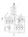
- Figure 1 illustrates the structure of a household network to which control unit 100 is connected.
- control unit 100 is connected to the electrical appliances in the household power line network.
- Control unit 100 is also connected to public network 102 (such as for example a PSTN, xDSL, WLL, cable network etc.) through a data communication line, and is the component through which public network 102 connects to the household power lines.
- public network 102 such as for example a PSTN, xDSL, WLL, cable network etc.
- Control unit 100 is connected to each electrical appliance in the home through household power line 103.
- Power line 103 receives electrical power from the electric power utility through circuit breaker "B", carries electrical power to each appliance, and also serves as the medium through which various communication and / or control signals travel between control unit 100 and interior lighting fixtures 104, 106 and 112, air conditioner 105, televisions 107 and 108, washing machine 109, microwave oven 110, and refrigerator 111.
- these appliance identifications are merely exemplary. Any types of such appliances are included in the present invention.
- all types of electrical tools and other electrical devices are also within the scope of the present invention.
- household power line 103 (hereafter referred to as power line 103) forms an in-house communications network through which control unit 100 is able to execute a centralized control function for each electric appliance.
- Control unit 100 and each electrical appliance are able to superimpose signals on the voltage of power line 103. That is, a Power Line Communication (PLC) unit is able to transmit a signal by combining the signal with a carrier wave on power line 103 to which electrical power is being supplied, and is able to receive the signal by extracting it from the voltage on power line 103.
- PLC Power Line Communication
- the PLC unit thus makes it possible to use power line 103 as a communications line that can be used by both control unit 100 and the appliances.
- An appropriate PLC unit is provided to each controlled appliance as well as to the control unit100.
- the PLC unit When power line 103 used as a communications line, the PLC unit, which is installed to each appliance, is able to provide a modem communications function based on the specific modulation method used by the appliance.
- the PLC unit in the control unit is able to provide a modem communications function through multiple modulation methods in order to communicate with an appliance through the specific modulation method used by that appliance.
- the multiple modulation method PLC unit installed to control unit 100 is called a multi-PLC unit in contrast to the single modulation method PCL unit installed to each appliance.
- FIG. 2 is a block diagram showing the basic structure of control unit 100 used in the description of the embodiment.
- control unit 100 includes CPU 201, memory 202 that stores the programs used by CPU 201 to control all the appliances, external interface 203 that connects the control unit to a public network through a communications circuit, and the previously described multi-PLC unit 204.
- memory 202 stores a data table (hereafter called an appliance data table) that is referenced when multi-PLC unit 204 communicates with an appliance.
- an appliance data table a data table that is referenced when multi-PLC unit 204 communicates with an appliance.
- FIG. 3 provides an example of the appliance data table stored in memory 202 of control unit 100 as embodied in the present invention.
- This appliance data table contains appliance data that has been previously stored in the table.
- Appliance data table 300 contains data indicating the type of modulation method 302, the data transmission speed 303, the address 304, and, other data, such as the modulation method 305 for the PLC unit installed to each appliance 301 connected to power line 103.
- the PLC unit installed to air conditioner 105 uses the PSK modulation method and that the data transmission speed is 5,400bps.
- Data has also been registered in the table showing that air conditioner 105 can be addressed at 0X0105, and that it is compatible with the Echonet protocol.
- Figure 4 is a block diagram illustrating the structure of multi-PLC unit 204 in control unit 100.
- Coupler 401 which is contained in multi-PLC unit 204, extracts only a signal within the bandwidth used for power line communications.
- Band pass filter 402 allows passage only of power line communications signals by filtering out electrical noise from motors and other electrical devices.
- A/D converter 403 performs an analog-digital switching function for the signals extracted by the band pass filter.
- Modulator 404 selects the modulation method instructed by CPU 201, and applies a modulation processing operation to the signals output by each appliance.
- Demodulator 405 determines the demodulation method of signals received from each appliance, and applies a demodulation processing operation to those signals.
- Modulator 404 contains AKS modulator 406, FSK modulator 407, PSK modulator 408, and modulation switcher 409 that respectively conduct ASK, FSK, and PSK modulation processing for signals transmitted by the appliances. Furthermore, modulators 406, 407, and 408 are structured to be compatible with multiple modulation speeds (data transmission speeds). Modulation switcher 409 performs a selection operation between ASK modulator 406, FSK modulator 407, and PSK modulator 408 based on transmission signal addresses specified by CPU 201.
- Demodulator 405 contains ASK demodulator 410, FSK demodulator 411, PSK demodulator 412, received signal modem determinator 413 (hereafter referred to as determinator 413), and energy sensor 414.
- ASK demodulator 410, FSK demodulator 411, and PSK demodulator 412 respectively apply ASK, FSK, and PSK demodulation processing methods to signals received from the appliance.
- demodulators 411, 412, and 413 are structured to be compatible with multiple demodulation speeds (data transmission speeds).
- Determinator 413 ascertains the modulation method for received signals, and selects the appropriate demodulator from among ASK demodulator 410, FSK demodulator 411, and PSK demodulator 412 .
- Energy sensor 414 detects a signal that has an energy value above a specific energy for a predetermined frequency bandwidth, and notifies determinator 413 and CPU 201 of that signal.
- determinator 413 initiates the processing operation through which a modulation method is determined for the received signal.
- CPU 201 upon being notified of the received signal, stops the output of the transmission signal to the appliance. The process through which determinator 413 ascertains the modulation method for the received signal will be explained subsequently.
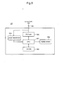
- FIG. 5 is a block diagram illustrating the basic structure of an electrical appliance connected to control unit 100 through power line 103.
- control unit 100 For explanatory purposes, the following explanation will refer to the appliance in Figure 5 as television 107.
- Television 107 includes a CPU 501 that controls all television operations, memory 502 that stores television control programs run by CPU 501 and the address of control unit 100 required for power line communications.
- a power transformer 503 transforms incoming power from power line 103 into power that can be used by the internal microcomputer, screen 504 displays the televised image, and PLC unit 505 that provides the modem function for power line communications.
- memory 502 may also stored the addresses of other appliances that are connected to household power line 103 and that use the same modulation method as that of television 107. If this is the case, CPU 501 may execute a power line communication control function with the other appliances that use the same modulation method without going through control unit 100.
- FIG 6 is a block diagram illustrating PLC unit 505 contained in television 107 which is connected to control unit 100 through power line 103. As shown by Figure 6, television 107 is able to communicate through household power lines by the FSK modulation method (other modulation methods can be utilized in the same general manner).
- Coupler 601 which is contained within PLC unit 505, extracts only the signals within the bandwidth utilized for power line communications.
- Band pass filter 602 allows only power line communication signals to pass by filtering out electrical noise and other signals generated by electric motors and other devices.
- A/D converter end 603 performs an analog-digital switching operation to the signals extracted by the band pass filter.
- FSK modulator 604 applies FSK modulation processing to the transmission signal sent to control unit 100
- FSK demodulator 605 applies FSK demodulation processing to the signal received from control unit 100.
- Energy sensor 606 detects a signal that has an energy value above a specific energy value for a predetermined frequency bandwidth, and notifies FSK demodulator 605 and CPU 501 of the presence of such signal. Upon receiving this notification, FSK demodulator 605 initiates demodulation processing.
- CPU 501 stops the transmission signal output to control unit 100 upon recognizing the presence of the received signal.
- Control unit 100 references the data contained in appliance data table 300, which is stored in memory 202, when executing the power line communications function for appliances connected to control unit 100 through power line 103. Therefore, the appropriate data must be placed into appliance data table 300 before the power line communications can be conducted. To do this, control unit 100 randomly or periodically generates control signals as means of ascertaining the modulation method for each appliance connected to power line 103, and receives an acknowledgement signal, in response to one of the aforesaid generated control signals, indicating the modulation method, of each appliance which is then recorded in the memory 202. Moreover, even before the aforesaid control signal is generated, when control unit 100 receives a signal output from any appliance in the network, control unit 100 may analyze the signal, extract data from the signal indicating the modulation method for that appliance, and record the extracted data.
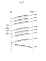
- Figure 7 is a chart illustrating the transmission sequence of control signals, output from control unit 100, which are utilized to ascertain the modulation method used by each appliance, and the acknowledgement response signal from the appliance.
- the chart of Figure 7 shows the transmission sequence for one appliance connected to power line 103, that appliance being, for the purpose of this explanation, television 107 which is described in Figure 5.
- control unit 100 outputs a sequence of various modulation method control signals, periodically or randomly, to the appliances connected to power line 103, as means of ascertaining the modulation method of the appliance to which said signals are transmitted.
- control signals As the purpose of the control signals is to elicit an acknowledgment response from the appliance, they will be hereafter be referred to as "inquiry signals.”
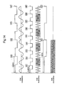
- Figure 8 is a diagram showing one example of data frames that can be used for data exchange between control unit 100 and each appliance.
- the data frames in Figure 8 are seen to include a preamble frame 801 that indicates the initiation of data transmission, a sender address frame 802, a destination address frame 803, a data type frame 804, a user data frame 805 that contains message data for the user, a cyclic redundancy check (CRC) frame 806 that checks for bit transmission errors during the transmission, and a termination data frame 807 that indicates the end of the transmission.
- a preamble frame 801 that indicates the initiation of data transmission
- a sender address frame 802 a destination address frame 803, a data type frame 804, a user data frame 805 that contains message data for the user, a cyclic redundancy check (CRC) frame 806 that checks for bit transmission errors during the transmission, and a termination data frame 807 that indicates the end of the transmission.
- CRC cyclic redundancy check
- sender address frame 802 contains the address of control unit 100
- destination address frame 803 contains the addresses of all appliances connected to power line 103, that is, the inquiry signal is broadcast to all addresses.
- data type frame 804 indicates an inquiry signal
- user data frame 805 contains data indicating the modulation method specified by the inquiry signal.
- control unit 100 first outputs an inquiry signal, based on the ASK modulation method, to television 107. To prevent transmission errors, control unit 100 will output the inquiry signal up to a predetermined number of times, for example only, for three times, if a response signal is not received within a specific time period following each inquiry signal. Because television 107 uses an FSK modulation method for power line communications (see Figure 6), it will not respond to the ASK inquiry signal (see ST702 in Figure 7).
- control unit 100 will output a PSK modulation method inquiry signal a maximum of e.g. three times (ST703) in the same manner as the previous ASK inquiry signal.
- Television 107 being only compatible with the FSK method, will not accordingly respond to the PSK inquiry signal (ST704).
- control unit 100 will output an FSK modulation method inquiry signal to television 107 (ST705). Because television 107 is only able to communicate through the FSK modulation method, it will only respond to the FSK inquiry signal by transmitting an acknowledgement signal back to the control unit 100 (ST706).
- control unit 100 Upon receiving a response i.e. acknowledgment signal, control unit 100 is able to determine that the appliance (television 107) is compatible with the FSK modulation method, and is thus able to place data indicating that modulation method into appliance data table 300 in memory 201.
- Control unit 100 is able to execute this type of modulation method recording operation for each appliance connected to power line 103.
- data pertaining to the modulation method for each appliance connected to power line 103 can be placed in appliance data table 300 in memory 202.
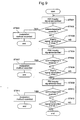
- Figure 9 is a flowchart illustrating the operation of control unit 100 executing the signal transmission sequence shown in Figure 7.
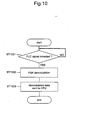
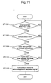
- Figures 10 and 11 are flowcharts explaining the operation of the appliance during the signal transmission sequence shown in Figure 7.
- Figure 10 shows the operation of PLC unit 505 in television 107
- Figure 11 shows the operation of CPU 501 in television 107.
- control unit 100 initially outputs i.e. transmits an ASK inquiry signal to the appliance (ST901) after which it is determined if a response has been received from the appliance within a specified time period (ST902). If a response signal is received, control unit 100 recognizes that the appliance is able to respond to the ASK inquiry signal, places data into appliance data table 300 in memory 202 indicating that the appliance is compatible with the ASK modulation method (ST903), and terminates the operation. At this point, control unit 100 has also recorded the data transmission speed based on the shift point in the reply signal carrier wave. According to the sequence shown in Figure 7, however, as television 107 is only able to communicate through the FSK modulation method, television 107 will not respond to the ASK inquiry signal.
- the signal will be transmitted a predetermined number of times and the control unit 100 will recognize a condition in which the inquiry signal has been output e.g. three times with no response (ST904). It is possible to avoid errors, which lack of a response may cause, by repeatedly outputting the inquiry signal for e.g. three times in the signal transmission sequence.
- this control sequence returns to ST901, and runs the same sequence again, as noted above.
- the PSK modulated inquiry signal will be output in the same manner as the ASK inquiry signal in steps ST901 through ST904. That is, the PSK inquiry signal is output to the appliance (ST905) after which a determination is made as to whether a response signal has been received within the allotted time (ST906). If a response signal is received, it indicates that the appliance is able to respond to the PSK inquiry signal, thus causing data indicating the compatibility of the appliance to be placed into appliance data table 300 in memory 202 (ST907), and the signal inquiry operation to terminate. Conversely, if a response signal is not received, it is determined that the PSK inquiry signal has been output three times without a response (ST908). According to the transmission sequence shown in Figure 7, there would be no response to the PSK inquiry signal because television 107 is only compatible with the FSK modulation method.
- the FSK modulated inquiry signal will be output in the same manner as the PSK modulated inquiry signal was in steps ST905 through ST908. That is, the FSK inquiry signal is output to the appliance (ST909) after which a determination is made if a response signal has been received within the allotted time (ST910). If a response signal is received, it indicates that the appliance is able to respond to the FSK inquiry signal, thus resulting in data indicating the condition to be placed into appliance data table 300 in memory 202 (ST911), and the signal inquiry operation to terminate. If a response signal is not received, it is determined that a condition exists in which the FSK inquiry signal has been output three times without a response (ST912). According to the signal transmission sequence shown in Figure 7, a response signal from television 107 will be received because television 107 uses the FSK modulation method. Therefore, data indicating that television 107 uses the FSK modulation method will be placed in appliance data table 300.
- PLC unit 505 monitors for the detection of the frequency bandwidth signal (hereafter referred to as the PLC signal) which is used for power line communications and which includes the inquiry signal.
- the PLC signal is detected (ST1001)
- PLC unit 505 will demodulate the PLC signal using the integrated FSK modulation method (ST1002), and send the demodulated data to CPU 501 (ST1003).
- CPU 501 which is installed in the appliance (in this case television 107), detects the data transmission from PCL unit 505. If the demodulated data from PLC unit 505 is received by CPU 501, (ST1101), that data is tested to ascertain if it has been demodulated in the correct format (ST1102). This test for correct demodulation format can be conducted to verify, for example, if a CRC (cyclic redundancy check) has been added to the post-demodulation data frame.
- CRC cyclic redundancy check
- the address of the demodulated data corresponds to the address of the appliance (ST1103). Specifically, it is determined if the address of television 107 is contained in the demodulation data destination address frame.
- the address specified in the demodulated data corresponds to the appliance, it is then determined whether or not the data type in the modulation data frame should be treated as new data for first-time recording. (ST1104). To determining whether or not the data type denotes a first-time data recording, prevents an appliance that has sent a response signal to the control unit 100 before, from replying to the inquiry signal again.
- CPU 501 instructs PCL unit 505 to send the response signal to control unit 100 (ST1105), and the processing operation is completed. A response signal is then sent by PLC unit 505 to control unit 100 as instructed by CPU 501.
- control is returned to await receipt of another data from PLC unit 505.
- control unit 100 is able to verify and record the modulation method for the modem installed in each appliance even though the modulation method may be different for each PCL unit 505 which provides the modem function for each appliance connected to power line 103. Because this operation allows control unit 100 to operate according to the specific modulation method used by each appliance, it becomes possible to establish a power line communications system which does not require that all appliances be equipped with modems using the same modulation method.
- control unit 100 periodically outputs control signals to verify the modulation method used by the modem installed to each appliance connected to power line 103. As this operation verifies the modulation method for the modem installed to each appliance, the modulation method is automatically recorded, without the possibility of error, even for e.g. newly purchased appliances that have been recently connected to the system.
- the embodiment describes a periodically output control signal employed as means of verifying the modem modulation method used by each appliance
- the control signal may also be transmitted at random time intervals.
- the modem modulation method for the new appliance may be initially recorded through a manual data recording operation at the time of installation.
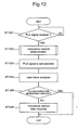
- Figure 12 is a flowchart showing the operation of control unit 100 when a modulation method signal is received from an appliance and the modulation method is determined based on the signal.
- the operation shown in Figure 12 describes a processing example in which an appliance has been newly connected to power line 103 and the modulation method used by the appliance is communicated to control unit 100.
- the appliance set a previously determined temporary address in the sender address 802, and sends, to control unit 100, a PLC signal which indicates that this message is intended for first-time recording of a modem method.
- control unit 100 is in standby status while waiting for a PCL signal from an appliance connected to power line 103. If a PLC signal is received from an appliance (ST1201), a process is applied to determine if the incoming signal is a PLC signal denoting a modulation method (ST1202). This modulation method determination process, which will be subsequently explained with reference to Figure 13, is applied to detect the modulation method of the PLC signal received by control unit 100.
- control unit 100 demodulates the PCL signal (ST1203) and analyzes the contents of the demodulated data frame (ST1204).
- the temporary address is set in sender address 802, and data type 804 is recognized as a first-time recording.
- the modulation method data monitored at ST1202 is set into appliance table 300 (ST1206) and the operation is terminated. Conversely, if it is determined that the data already exists in table 300, the operation is terminated without any data recordation.
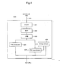
- Figure 13 is a flowchart that describes the process through which control unit 100 determines the modulation method.
- the modulation method determination is executed by determinator 413 which is installed within multi-PCL unit 204 in control unit 100.
- the modulation method determination begins when control unit 100 detects the modulation method of the PCL signal output from the appliance (ST1301). More specifically, control unit detects the shift point of the carrier wave which is the base of the PLC signal, and is thus able to detect the modulation method used by the appliance sending the PLC signal.
- the carrier wave which is the base of the PLC signal
- the carrier wave is transmitted with changes in phase.
- the modulation method is the FSK type
- the carrier wave is transmitted with changes in frequency.
- the modulation method is the ASK type
- the carrier wave is transmitted with changes in amplitude.
- Control unit 100 is able to detect the phase shift points for PSK modulation, frequency shift points for FSK modulation, and amplitude shift points for ASK modulation, and is thus able to recognize the modulation method used by the transmitting appliance.
- Figure 14 is a frequency graph illustrating the shift points for each type of modulation method monitored by control unit 100 when a modulation method is contained in the transmission signal from the appliance.
- Points A1, A2, A3, and A4 are the phase shift points monitored for a PSK modulation.
- B1, B2, B3, B4, B5, B6, B7, and B8 are the frequency shift points monitored for an FSK modulation.
- C1 and C2 are the amplitude shift points monitored for an ASK modulation.
- control unit 100 After detecting the modulation method in the appliance transmission signal, control unit 100 determines whether the modulation method is an ASK type (ST1302), PSK type (ST1303), or FSK type (ST1304).
- the data transmission speed which is based on the time interval within which the shift point of the carrier wave appears, is monitored for each modulation method (ST1305-ST1307), and the monitored transmission speed and modulation method are recorded in appliance data table 300 of memory 202 (ST1308-ST1310). Furthermore, in regard to the FSK modulation method, which is the last modulation method to be determined in this process, in the event that there is no recognized FSK modulation method, an error condition is recognized and the processing sequence returns to ST1301.
- control unit 100 Even when control unit 100 does not registered the modulation method of the PCL unit that functions as a modem of the appliance, control unit 100 is able to ascertain and record the modulation method utilized in the modem of the appliance based on any signal output by the appliance. Thus, even when the modulation method utilized in the modem of in each appliance connected to power line 103 is different, control unit 100 is still able to execute a control function for each appliance by applying the appropriate modulation method for the appliance and using household power lines as the communications medium. Thus, the present invention is able to eliminate the requirement that all appliances in a power line communications system be equipped with modems that use the same modulation method.
- control unit 100 executes control of all appliances in a household power line communications system in which the appliances connected thereto are equipped with modems that use different modulation methods.
- the drawing in Figure 15 illustrates the sequence through which control unit 100 controls power line communications between appliances that use different modulation methods.
- Figure 15 illustrates an example of how communications are controlled between refrigerator 111, which uses the ASK modulation method, and television 107, which uses the FSK modulation method. Specifically, this example shows the process through which an alarm message and verification message from refrigerator 11 are displayed on the screen of television 107. Furthermore, data pertaining to the modulation methods used by refrigerator 111 and television 107 are recorded in appliance data table 300 before messages are sent from refrigerator 111 and sent to television 107.
- an alarm message is output in the event that the refrigerator door has been left open longer than a specific time duration, and a verification message is output if the refrigerator door has been closed after being open for a specific time duration.
- an alarm message is sent from refrigerator 111 to control unit 100 (ST1501).
- the ASK modulation method used by refrigerator 111 is applied to the alarm message.
- Control unit 100 analyzes the ASK-modulated alarm message, and then applies an FSK modulation processing operation to the signal due to the signal destination being television 107 which uses the FSK modulation method (ST1502).
- Television 107 analyzes the verification message and displays the message on screen 504.
- refrigerator 111 The door of refrigerator 111 is then manually closed (ST1503) which results in refrigerator 111 outputting a verification message to control unit 100 (ST1504).
- the ASK modulation method used by refrigerator 111 is applied to the verification message.
- Control unit 100 analyzes the ASK-modulated verification message, and then applies an FSK modulation processing operation to the signal due to the signal destination being television 107 which uses the FSK modulation method (ST1505).
- Television 107 analyzes the alarm message and displays the message on screen 504.
- Figure 16 and 17 are flowcharts that explain the operation of refrigerator 11 during the signal sequence shown in Figure 15.
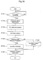
- Figure 18 explains the operation of control unit 100 during the signal sequence shown in Figure 15.
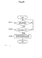
- Figures 19 and 20 explain the operation of television 107 during the signal sequence shown in Figure 15.
- Figure 16 explains the operation of refrigerator 111 when the door has been monitored as being open for a specific time duration.
- Figure 17 explains the operation of refrigerator 111 when the door has been monitored as being closed after being open for a specific time duration.
- Figure 19 shows the operation of PLC unit 505 in television 107
- Figure 20 shows the operation of CPU 501 in television 107.
- refrigerator 111 normally monitors for an open door condition. If a door open condition is monitored (ST1601), the door open time is also monitored to determine if the open time exceeds a specified time duration (ST1602).
- the ASK modulator in the PLC unit of refrigerator 111 applies ASK modulation to the alarm message output to control unit 100 (ST1603).
- a "1" is then set (ST1604) for the open flag, after which the operation is terminated.
- refrigerator 111 normally monitors for a door closed condition in the same manner as for a door open condition.
- a door closed condition is monitored (ST1701)
- a determination is made as to whether a "1" has been set for the open flag (ST1702).
- the ASK modulator in the PLC unit of refrigerator 111 applies an ASK modulation to the verification message output to control unit 100 (ST1703).
- a "0" is then set (ST1704) for the open flag, after which the operation terminates.
- control unit 100 which is in a standby condition, monitors for PLC signal output from an appliance. If a PLC signal from an appliance connected to power line 103 is received (ST1801), a modulation method determination is conducted to ascertain the modulation method of the PLC signal (ST1802).
- the modulation method determination executed here will not be explained as it is essentially the same as the previously explained procedure relating to Figure 13. This modulation method determination may be omitted if data indicating the modem modulation method is already registered.
- control unit 100 demodulates the PLC signal (ST1803), and the contents of the demodulated data frame is analyzed (ST1804).
- the address allocated for refrigerator 111 (0X0111 in Figure 3) is written into transmission origin (e.g. sender address) data frame 802
- the address allocated for television 107 (0X0107) is written in to destination address data frame 803, and the data in data type designation frame 804 is ascertained to be an alarm message.
- control unit 100 determines, based on the address indicated by the analyzed data for the destination address in frame 803, whether or not data indicating the alarm message sender has been registered in appliance data table 300 (ST1805). As mentioned previously, data pertaining to the modulation method used by television 107 has been placed into appliance data table 300.
- control unit 100 references the modulation method data held in appliance data table 300 (ST1806). As shown in Figure 3, as there is data in appliance data table 300 indicating that television 107 uses the FSK modulation method, the fact that television 107 uses the FSK modulation method can be readily referenced by control unit 100.
- control unit 100 is able to modulate the alarm message output by refrigerator 111 accordingly, and send that modulated alarm message to television 107 (ST1807).
- the alarm message is sent to television 107 after the FSK modulation process has been applied in order that the modulation method of the message signal corresponds to that of the destination, which is television 107.
- control unit 100 in the event that data indicating the modulation method is not stored in appliance data table 300 (ST1805), control unit 100, as shown in Figure 9, will enter the modulation method data into appliance data table 300 for the appliance connected to power line 103 (ST1808). Therefore, control unit 100 is able to recognize the modulation method used by the destination appliance (which in this case is television 107), modulate the alarm signal output from refrigerator 111 based on the aforesaid modulation method, and send that modulated alarm message to television 107.
- the destination appliance which in this case is television 107
- the signal processing operation for the verification message is conducted in essentially the same manner.
- the verification signal from refrigerator 111 is demodulated according to the modulation method used by refrigerator 111, after which the signal is modulated according to the modulation method used by television 107, and then output to television 107.
- PLC unit 505 of television 107 will monitor for a PLC signal when electrical power is turned on. If a PLC signal is detected (ST1901), PLS unit 505 will demodulate the PLC signal according to the resident FSK modulation method, and send the demodulated data to CPU 501 (ST1903).
- CPU 501 in television 107 monitors the data transmission from PLC unit 505.
- demodulated data is received from PLC unit 505 (ST2001)
- ST2002 a determination is made as to whether that data has been appropriately demodulated (ST2002). This can be done, for example, by verifying that a CRC has been applied to the modulated data frame.
- television 107 displays the data on-screen (ST2003). This operation allows the alarm message sent by refrigerator 111 to be displayed on screen 504 of television 107. Furthermore, while this explanation has covered the operation through which an alarm message can be displayed on screen 504 of television 107, the operation through which a verification message is received in order to remove the alarm message from screen 504 is also conducted through the operation shown in the Figure 20 flowchart.
- control unit 100 is able to provide a communications function between a first appliance (refrigerator 111) and a second appliance (television 107), based on data, held in appliance data table 300, that relates to the modulation method used by each appliance.
- control unit 100 changes the control signal from one corresponding to the modulation method used by the modem of the first appliance (refrigerator 111) to one that corresponds to the modulation method used by the modem of the second appliance (television 107), and thus makes possible power line communications between appliances even in cases where the appliances connected to power line 103 are equipped with PLC modems that operate according to different modulation methods.
- television 107 is able to display a message indicating that the door of refrigerator 111 has been left open more than a specified time period, thus demonstrating that power line communications between household appliances can be conducted without the requirement that the appliances be equipped with modems using the same modulation method.
- control unit 100 may also be installed internally to each appliance. If internally installed, it is obvious that control unit 100 would provide the same function, operation, and results as already described in the embodiment. Furthermore, both control unit 100 and another apparatus that performs the same control functions as control unit 100 may be provided in the system. For example, the other apparatus that executes the same control functions as control unit 100 is set as a sub-control in the system. Accordingly, when the control unit 100 can not function adequately due to a change in communication status, the other apparatus can support the control unit 100 so as to continue communications with the other appliances.
- the present invention is able to control communication between all appliances connected to a household power line, even in Europe where no modem standard has been established for household power line communications. Furthermore, the present invention does not require that appliances in a power line communications network be equipped with modems that use the same modulation method.
Landscapes
- Engineering & Computer Science (AREA)
- Computer Networks & Wireless Communication (AREA)
- Signal Processing (AREA)
- Power Engineering (AREA)
- Automation & Control Theory (AREA)
- Environmental & Geological Engineering (AREA)
- Human Computer Interaction (AREA)
- Cable Transmission Systems, Equalization Of Radio And Reduction Of Echo (AREA)
- Selective Calling Equipment (AREA)
- Remote Monitoring And Control Of Power-Distribution Networks (AREA)
Applications Claiming Priority (2)
| Application Number | Priority Date | Filing Date | Title |
|---|---|---|---|
| JP2002367803A JP4473504B2 (ja) | 2002-12-19 | 2002-12-19 | 電化製品を電灯線通信により制御する管理装置及びその制御方法 |
| JP2002367803 | 2002-12-19 |
Publications (2)
| Publication Number | Publication Date |
|---|---|
| EP1432099A2 true EP1432099A2 (de) | 2004-06-23 |
| EP1432099A3 EP1432099A3 (de) | 2005-11-02 |
Family
ID=32376287
Family Applications (1)
| Application Number | Title | Priority Date | Filing Date |
|---|---|---|---|
| EP03029077A Withdrawn EP1432099A3 (de) | 2002-12-19 | 2003-12-17 | Steuervorrichtung und -verfahren zur Abwicklung des Informationsaustausches zwischen mehreren Elektrogeräten über die Haushaltsstromversorgung |
Country Status (3)
| Country | Link |
|---|---|
| US (1) | US6975211B2 (de) |
| EP (1) | EP1432099A3 (de) |
| JP (1) | JP4473504B2 (de) |
Cited By (4)
| Publication number | Priority date | Publication date | Assignee | Title |
|---|---|---|---|---|
| CN101834634A (zh) * | 2010-04-16 | 2010-09-15 | 龚黎 | Fsk和psk双模多频电力线载波调制解调器 |
| EP2074250A4 (de) * | 2007-08-16 | 2011-04-20 | Lg Electronics Inc | Komplettsystem zur wäschebehandlung |
| CN102025398B (zh) * | 2009-09-11 | 2014-07-23 | 中颖电子股份有限公司 | 有线载波通信方法与装置 |
| EP2751874B1 (de) * | 2011-09-01 | 2020-04-29 | Daniel P. Casey | Sicherheitsneuentwurf eines stromkastens |
Families Citing this family (50)
| Publication number | Priority date | Publication date | Assignee | Title |
|---|---|---|---|---|
| US6480510B1 (en) | 1998-07-28 | 2002-11-12 | Serconet Ltd. | Local area network of serial intelligent cells |
| US6549616B1 (en) | 2000-03-20 | 2003-04-15 | Serconet Ltd. | Telephone outlet for implementing a local area network over telephone lines and a local area network using such outlets |
| US6842459B1 (en) | 2000-04-19 | 2005-01-11 | Serconet Ltd. | Network combining wired and non-wired segments |
| IL152824A (en) | 2002-11-13 | 2012-05-31 | Mosaid Technologies Inc | A socket that can be connected to and the network that uses it |
| US7154381B2 (en) * | 2003-05-23 | 2006-12-26 | Sonos, Inc. | System and method for operating a sensed power device over data wiring |
| US8090857B2 (en) | 2003-11-24 | 2012-01-03 | Qualcomm Atheros, Inc. | Medium access control layer that encapsulates data from a plurality of received data units into a plurality of independently transmittable blocks |
| IL160417A (en) | 2004-02-16 | 2011-04-28 | Mosaid Technologies Inc | Unit added to the outlet |
| KR100600734B1 (ko) * | 2004-02-25 | 2006-07-14 | 엘지전자 주식회사 | 홈네트워크 시스템 및 그 제어 방법 |
| US8024055B1 (en) | 2004-05-15 | 2011-09-20 | Sonos, Inc. | Method and system for controlling amplifiers |
| US7372831B2 (en) * | 2004-08-11 | 2008-05-13 | Lg Electronics Inc. | Packet transmission acknowledgement in wireless communication system |
| JP4543817B2 (ja) * | 2004-08-13 | 2010-09-15 | パナソニック電工株式会社 | 電力線搬送通信装置 |
| ES2255835B1 (es) * | 2004-09-15 | 2007-08-01 | Sociedad Europea De Redes Virtuales E Ingenieria Telematica S.L. | Sistema modular de control inteligente y conexionado para instalacion domotica. |
| US7183902B2 (en) * | 2004-09-30 | 2007-02-27 | Hewlett-Packard Development Company, L.P. | Very local area network (VLAN) |
| US7873058B2 (en) | 2004-11-08 | 2011-01-18 | Mosaid Technologies Incorporated | Outlet with analog signal adapter, a method for use thereof and a network using said outlet |
| US20070025266A1 (en) * | 2005-07-27 | 2007-02-01 | Neal Riedel | Communicating schedule and network information in a powerline network |
| US8175190B2 (en) | 2005-07-27 | 2012-05-08 | Qualcomm Atheros, Inc. | Managing spectra of modulated signals in a communication network |
| US8737420B2 (en) * | 2005-07-27 | 2014-05-27 | Sigma Designs Israel S.D.I. Ltd. | Bandwidth management in a powerline network |
| US8553706B2 (en) * | 2005-07-27 | 2013-10-08 | Coppergate Communications Ltd. | Flexible scheduling of resources in a noisy environment |
| JP4525569B2 (ja) * | 2005-11-21 | 2010-08-18 | トヨタ自動車株式会社 | 通信装置 |
| DE102006015840A1 (de) * | 2006-04-03 | 2007-10-04 | Miele & Cie. Kg | Bedien- und Anzeigevorrichtung für ein Haushaltgerät, Haushaltgerät und System |
| JP4527684B2 (ja) * | 2006-05-16 | 2010-08-18 | 三菱電機株式会社 | 通信装置及び通信システム |
| JP4811253B2 (ja) * | 2006-12-01 | 2011-11-09 | 船井電機株式会社 | 電力線搬送通信システム |
| WO2008091255A1 (en) | 2007-01-25 | 2008-07-31 | Thomson Licensing | Frequency translation module interface |
| JP4416008B2 (ja) * | 2007-05-18 | 2010-02-17 | ソニー株式会社 | 通信装置及び通信方法 |
| KR100965701B1 (ko) * | 2007-06-08 | 2010-06-24 | 파나소닉 전공 주식회사 | 전력선 반송 통신 시스템 |
| AU2008274892A1 (en) * | 2007-07-09 | 2009-01-15 | Semitech Semiconductor Pte Ltd | Communication methods and devices |
| JP5156920B2 (ja) * | 2008-10-03 | 2013-03-06 | ネッツエスアイ東洋株式会社 | 電力線搬送通信装置 |
| JP5205605B2 (ja) * | 2008-10-03 | 2013-06-05 | ネッツエスアイ東洋株式会社 | 電力線搬送通信装置 |
| KR101563487B1 (ko) * | 2009-05-11 | 2015-10-27 | 엘지전자 주식회사 | 가전기기를 제어하는 휴대 단말기 |
| WO2010131305A1 (ja) | 2009-05-15 | 2010-11-18 | パナソニック株式会社 | 電力線通信装置、及び電力線通信システム |
| US20110005258A1 (en) * | 2009-07-09 | 2011-01-13 | Mathieu Audet | Method and system for managing appliance equipments |
| CN102195677B (zh) * | 2010-03-10 | 2014-03-12 | 青岛东软载波科技股份有限公司 | 接收电路、发送电路、微控制器及电力线载波通信方法 |
| US8681619B2 (en) * | 2010-04-08 | 2014-03-25 | Landis+Gyr Technologies, Llc | Dynamic modulation selection |
| JP5202572B2 (ja) * | 2010-05-07 | 2013-06-05 | 三菱電機株式会社 | 空気調和機及び空気調和機システム |
| KR101025789B1 (ko) * | 2010-10-15 | 2011-04-04 | 한국전력공사 | 데이터 처리 장치 및 신호 충돌 방지 방법 |
| JP2012129809A (ja) * | 2010-12-15 | 2012-07-05 | Enecyber Inc | 電力線を用いたデータ伝送装置 |
| CN104204821B (zh) * | 2012-04-09 | 2017-02-22 | 英派尔科技开发有限公司 | 智能家电登记 |
| CN102769591B (zh) * | 2012-06-21 | 2015-04-08 | 天地融科技股份有限公司 | 音频通信调制方式自适应的方法、系统、装置、电子签名工具 |
| US9244516B2 (en) | 2013-09-30 | 2016-01-26 | Sonos, Inc. | Media playback system using standby mode in a mesh network |
| US10571869B2 (en) * | 2014-10-29 | 2020-02-25 | Xiaomi Inc. | Systems for mode switching in an appliance |
| JP6130077B2 (ja) * | 2014-11-28 | 2017-05-17 | 三菱電機株式会社 | 制御装置、通信システム、通信方法、及び、プログラム |
| CN105573282B (zh) * | 2016-02-03 | 2020-03-17 | 京东方科技集团股份有限公司 | 一种家庭电网 |
| JP6772048B2 (ja) * | 2016-12-14 | 2020-10-21 | ルネサスエレクトロニクス株式会社 | レート判定装置、レート判定方法及び受信装置 |
| JP6419250B2 (ja) * | 2017-04-12 | 2018-11-07 | 三菱電機株式会社 | 制御装置、通信システム、通信方法、及び、プログラム |
| CN112489340A (zh) * | 2019-09-12 | 2021-03-12 | 华为技术有限公司 | 消防终端、消防控制端以及消防方法 |
| US12192028B2 (en) | 2021-05-19 | 2025-01-07 | Focus Universal Inc. | System and method for a smart home system |
| US11546017B2 (en) | 2019-11-29 | 2023-01-03 | Focus Universal Inc. | System and method of power line communication |
| CN111917514B (zh) * | 2020-07-29 | 2023-05-19 | 天地融科技股份有限公司 | 一种数据传输方法及装置 |
| CN112365701A (zh) * | 2020-10-27 | 2021-02-12 | 广东电网有限责任公司广州供电局 | 一种电表数据采集方法、装置、设备和存储介质 |
| US11683875B2 (en) * | 2021-05-19 | 2023-06-20 | Focus Universal Inc. | Power line communication to control lighting |
Citations (3)
| Publication number | Priority date | Publication date | Assignee | Title |
|---|---|---|---|---|
| JP2001197249A (ja) * | 2000-01-17 | 2001-07-19 | Canon Inc | ファクシミリ装置及びその通信方法 |
| JP2002051069A (ja) * | 2000-08-07 | 2002-02-15 | Nippon Telegr & Teleph Corp <Ntt> | ゲートウェイ装置 |
| JP2002342724A (ja) * | 2001-05-18 | 2002-11-29 | Nippon Signal Co Ltd:The | 非接触型icカード用リーダライタ |
Family Cites Families (20)
| Publication number | Priority date | Publication date | Assignee | Title |
|---|---|---|---|---|
| US4429299A (en) * | 1979-01-05 | 1984-01-31 | Robertshaw Controls Company | Two-way AC power line communications system |
| US4580276A (en) * | 1983-08-05 | 1986-04-01 | Consultant's Choice Inc. | System and method for transporting data |
| US5818603A (en) * | 1996-03-29 | 1998-10-06 | Ricoh Company, Ltd. | Method and system for controlling and communicating with machines using multiple communication formats |
| US5084903A (en) * | 1989-02-28 | 1992-01-28 | First Pacific Networks | Modulation and demodulation system employing AM-PSK and QPSK communication system using digital signals |
| US6104707A (en) * | 1989-04-28 | 2000-08-15 | Videocom, Inc. | Transformer coupler for communication over various lines |
| FR2678084B1 (fr) * | 1991-06-24 | 1993-09-24 | Sgs Thomson Microelectronics | Procede pour communiquer des informations et commandes au sein d'une habitation ou d'un immeuble, systeme pour sa mise en óoeuvre, et application de ce systeme a une installation domotique. |
| FR2736780B1 (fr) * | 1995-07-13 | 1997-09-26 | Sgs Thomson Microelectronics | Circuit d'affectation d'un canal de transmission sur le reseau electrique |
| GB2305074A (en) * | 1995-08-31 | 1997-03-26 | Id Systems Ltd | Apparatus for Remotely Reading Data Storage Devices |
| JPH09186635A (ja) * | 1995-12-29 | 1997-07-15 | Kokusai Electric Co Ltd | 等化器 |
| US5805053A (en) * | 1996-10-21 | 1998-09-08 | Elcom Technologies, Inc. | Appliance adapted for power line communications |
| US6175860B1 (en) * | 1997-11-26 | 2001-01-16 | International Business Machines Corporation | Method and apparatus for an automatic multi-rate wireless/wired computer network |
| JP3279277B2 (ja) * | 1999-02-19 | 2002-04-30 | 三菱電機株式会社 | マルチキャリア通信方法およびマルチキャリア通信装置 |
| EP1277352A1 (de) * | 2000-03-24 | 2003-01-22 | Icebox LLC | Multimodus-vorrichtung mit kommunikations- und steuermerkmalen |
| US6854059B2 (en) * | 2000-06-07 | 2005-02-08 | Conexant Systems, Inc. | Method and apparatus for medium access control in powerline communication network systems |
| JP2002084658A (ja) | 2000-09-07 | 2002-03-22 | Alps Electric Co Ltd | 家庭内ネットワークシステム |
| JP3679320B2 (ja) * | 2000-10-18 | 2005-08-03 | 三菱電機株式会社 | 電力線搬送通信装置 |
| US20020095662A1 (en) * | 2000-10-25 | 2002-07-18 | Ashlock Robert L. | Utilizing powerline networking as a general purpose transport for a variety of signals |
| JP4664524B2 (ja) * | 2001-05-21 | 2011-04-06 | 株式会社東芝 | ホームネットワークシステム |
| US6879806B2 (en) * | 2001-06-01 | 2005-04-12 | Zensys A/S | System and a method for building routing tables and for routing signals in an automation system |
| US7049939B2 (en) * | 2002-07-31 | 2006-05-23 | Matsushita Electric Industrial Co., Ltd | Power line carrier system |
-
2002
- 2002-12-19 JP JP2002367803A patent/JP4473504B2/ja not_active Expired - Fee Related
-
2003
- 2003-10-14 US US10/682,973 patent/US6975211B2/en not_active Expired - Fee Related
- 2003-12-17 EP EP03029077A patent/EP1432099A3/de not_active Withdrawn
Patent Citations (3)
| Publication number | Priority date | Publication date | Assignee | Title |
|---|---|---|---|---|
| JP2001197249A (ja) * | 2000-01-17 | 2001-07-19 | Canon Inc | ファクシミリ装置及びその通信方法 |
| JP2002051069A (ja) * | 2000-08-07 | 2002-02-15 | Nippon Telegr & Teleph Corp <Ntt> | ゲートウェイ装置 |
| JP2002342724A (ja) * | 2001-05-18 | 2002-11-29 | Nippon Signal Co Ltd:The | 非接触型icカード用リーダライタ |
Cited By (5)
| Publication number | Priority date | Publication date | Assignee | Title |
|---|---|---|---|---|
| EP2074250A4 (de) * | 2007-08-16 | 2011-04-20 | Lg Electronics Inc | Komplettsystem zur wäschebehandlung |
| CN102025398B (zh) * | 2009-09-11 | 2014-07-23 | 中颖电子股份有限公司 | 有线载波通信方法与装置 |
| CN101834634A (zh) * | 2010-04-16 | 2010-09-15 | 龚黎 | Fsk和psk双模多频电力线载波调制解调器 |
| CN101834634B (zh) * | 2010-04-16 | 2016-05-18 | 龚黎 | Fsk和psk双模多频电力线载波调制解调器 |
| EP2751874B1 (de) * | 2011-09-01 | 2020-04-29 | Daniel P. Casey | Sicherheitsneuentwurf eines stromkastens |
Also Published As
| Publication number | Publication date |
|---|---|
| JP4473504B2 (ja) | 2010-06-02 |
| US20040122531A1 (en) | 2004-06-24 |
| EP1432099A3 (de) | 2005-11-02 |
| US6975211B2 (en) | 2005-12-13 |
| JP2004201065A (ja) | 2004-07-15 |
Similar Documents
| Publication | Publication Date | Title |
|---|---|---|
| EP1432099A2 (de) | Steuervorrichtung und -verfahren zur Abwicklung des Informationsaustausches zwischen mehreren Elektrogeräten über die Haushaltsstromversorgung | |
| JP4849972B2 (ja) | 通信装置、通信システム、画像取得装置、動画取得装置、及びその設定方法 | |
| US7729375B2 (en) | Power line communication apparatus and data relay method | |
| US8374256B2 (en) | Communication apparatus and communication method | |
| US7049939B2 (en) | Power line carrier system | |
| US20090263999A1 (en) | Power plug, power outlet, power supply device and power supply system | |
| US20140036989A1 (en) | Method for establishing an ip-based communications connection between an electric vehicle and a charging control unit | |
| JP5528618B2 (ja) | 空調機器及び空調システム | |
| US20050220004A1 (en) | Repeater for power line communication system | |
| Lewandowski et al. | Interference analyses of Electric Vehicle charging using PLC on the Control Pilot | |
| US20210008998A1 (en) | Setting a communication parameter of a communication module of a charging station | |
| JP3011677B2 (ja) | 情報転送装置及び情報送信システム | |
| JPH11284552A (ja) | 電力線搬送通信システム | |
| JP4354058B2 (ja) | データ伝送装置及び該装置を用いた自動検針システム | |
| KR200353093Y1 (ko) | 다중 통신장치 간의 통신을 수행하기 위한 지능형 미터게이트 웨이 및 이를 이용한 고속 전력선 통신 시스템 | |
| JP4454884B2 (ja) | データ伝送装置、及び該装置を用いた自動検針システム | |
| CN120353326B (zh) | 一种电源管理模组、电子设备以及检测装置 | |
| CN101232587A (zh) | 接收系统和处理接口信息的方法 | |
| KR20050092161A (ko) | 다중 통신장치 간의 통신을 수행하기 위한 지능형 미터게이트 웨이 및 이를 이용한 고속 전력선 통신 시스템 | |
| CN120669671A (zh) | 一种车辆自动化测试系统及其方法 | |
| CN120935011A (zh) | 一种智能变电站通讯信息配置方法 | |
| KR101582643B1 (ko) | 고속전력선통신기술 기반의 어쏘시에이션 방법 | |
| CN112637704A (zh) | 用于电能表的远程通信方法、系统及存储介质 | |
| JPH0260327A (ja) | 可搬型マイクロ波中継装置 | |
| KR20000066797A (ko) | 전력선을 이용한 가스누설경보차단제어장치 |
Legal Events
| Date | Code | Title | Description |
|---|---|---|---|
| PUAI | Public reference made under article 153(3) epc to a published international application that has entered the european phase |
Free format text: ORIGINAL CODE: 0009012 |
|
| AK | Designated contracting states |
Kind code of ref document: A2 Designated state(s): AT BE BG CH CY CZ DE DK EE ES FI FR GB GR HU IE IT LI LU MC NL PT RO SE SI SK TR |
|
| AX | Request for extension of the european patent |
Extension state: AL LT LV MK |
|
| PUAL | Search report despatched |
Free format text: ORIGINAL CODE: 0009013 |
|
| AK | Designated contracting states |
Kind code of ref document: A3 Designated state(s): AT BE BG CH CY CZ DE DK EE ES FI FR GB GR HU IE IT LI LU MC NL PT RO SE SI SK TR |
|
| AX | Request for extension of the european patent |
Extension state: AL LT LV MK |
|
| RIC1 | Information provided on ipc code assigned before grant |
Ipc: 7H 02J 13/00 B Ipc: 7G 05B 19/02 A Ipc: 7H 04B 3/54 B |
|
| 17P | Request for examination filed |
Effective date: 20051214 |
|
| AKX | Designation fees paid |
Designated state(s): DE FR GB |
|
| RAP1 | Party data changed (applicant data changed or rights of an application transferred) |
Owner name: PANASONIC SYSTEM NETWORKS CO., LTD. |
|
| STAA | Information on the status of an ep patent application or granted ep patent |
Free format text: STATUS: EXAMINATION IS IN PROGRESS |
|
| 17Q | First examination report despatched |
Effective date: 20161212 |
|
| STAA | Information on the status of an ep patent application or granted ep patent |
Free format text: STATUS: THE APPLICATION HAS BEEN WITHDRAWN |
|
| 18W | Application withdrawn |
Effective date: 20170217 |